Table of Contents
Advertisement
Quick Links
Advertisement
Table of Contents
Troubleshooting

Related Manuals for Delta Electronics AC Motor Drive VFD-EL


Summary of Contents for Delta Electronics AC Motor Drive VFD-EL
- Page 4 The AC motor drive may be destroyed beyond repair if incorrect cables are connected to the input/output terminals. Never connect the AC motor drive output terminals U/T1, V/T2, and W/T3 directly to the AC mains circuit power supply. Ground the VFD-EL using the ground terminal. The grounding method must comply with the laws of the country where the AC motor drive is to be installed.
- Page 5 WARNING! DO NOT use Hi-pot test for internal components. The semi-conductor used in AC motor drive easily damage by high-voltage. There are highly sensitive MOS components on the printed circuit boards. These components are especially sensitive to static electricity. To prevent damage to these components, do not touch these components or the circuit boards with metal objects or your bare hands.
-
Page 6: Table Of Contents
Preface ... i Table of Contents ... iii Chapter 1 Introduction ... 1-1 1.1 Receiving and Inspection...1-2 1.1.1 Nameplate Information... 1-2 1.1.2 Model Explanation ... 1-2 1.1.3 Series Number Explanation ... 1-3 1.1.4 Drive Frames and Appearances ... 1-3 1.1.5 Remove Instructions ... 1-5 1.2 Preparation for Installation and Wiring...1-5 1.2.1 Ambient Conditions... -
Page 7: Table Of Contents
Chapter 3 Keypad and Start Up ...3-1 3.1 Description of the Digital Keypad ... 3-1 3.2 How to Operate the Digital Keypad ... 3-3 3.3 Reference Table for the 7-segment LED Display of the Digital Keypad 3- 3.4 Operation Method ... 3-4 3.5 Trial Run ... -
Page 8: Table Of Contents
5.14 Environmental Condition...5-9 5.15 Affecting Other Machines ...5-10 Chapter 6 Fault Code Information and Maintenance... 6-1 6.1 Fault Code Information ...6-1 6.1.1 Common Problems and Solutions... 6-1 6.1.2 Reset ... 6-5 6.2 Maintenance and Inspections ...6-5 Appendix A Specifications ... A-1 Appendix B Accessories ... -
Page 9: Table Of Contents
B.8.1 DeviceNet Communication Module (CME-DN01) ...B-16 B.8.1.1 Panel Appearance and Dimensions ...B-16 B.8.1.2 Wiring and Settings ...B-16 B.8.1.3 Power Supply ...B-17 B.8.1.4 LEDs Display...B-17 B.8.2 LonWorks Communication Module (CME-LW01) ...B-17 B.8.2.1 Introduction ...B-17 B.8.2.2 Dimensions ...B-17 B.8.2.3 Specifications ...B-18 B.8.2.4 Wiring ...B-18 B.8.2.5 LED Indications ...B-18... - Page 10 Appendix C How to Select the Right AC Motor Drive... C-1 C.1 Capacity Formulas ... C-2 C.2 General Precaution ... C-4 C.3 How to Choose a Suitable Motor... C-5...
- Page 11 This page intentionally left blank...
-
Page 12: Chapter 1 Introduction
The AC motor drive should be kept in the shipping carton or crate before installation. In order to retain the warranty coverage, the AC motor drive should be stored properly when it is not to be used for an extended period of time. Storage conditions are: CAUTION! Store in a clean and dry location free from direct sunlight or corrosive fumes. -
Page 13: Receiving And Inspection
Chapter 1 Introduction| 1.1 Receiving and Inspection This VFD-EL AC motor drive has gone through rigorous quality control tests at the factory before shipment. After receiving the AC motor drive, please check for the following: Check to make sure that the package includes an AC motor drive, the User Manual/Quick Start and CD. -
Page 14: Series Number Explanation
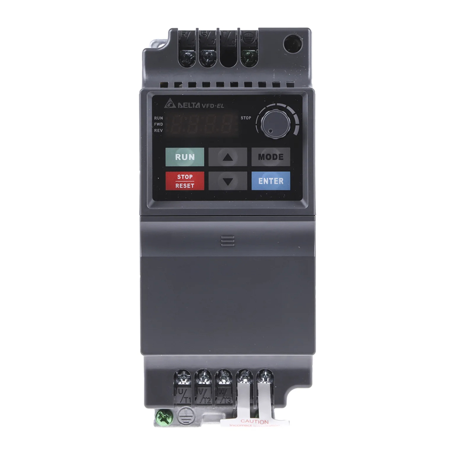
1.1.3 Series Number Explanation 007EL23A 230V 3-phase 1HP(0.75kW) If the nameplate information does not correspond to your purchase order or if there are any problems, please contact your distributor. 1.1.4 Drive Frames and Appearances 0.25-2HP/0.2-1.5kW (Frame A) Input terminals (R/L1, S/L2, T/L3) Digital keypad Control board cover Output terminals... - Page 15 Chapter 1 Introduction| Internal Structure RFI Jumper Location NOTE RFI jumper is near the input terminals as shown in the above figure and can be removed by taking off screws. Frame Power range 0.25-2hp (0.2-1.5kW) 1-5hp (0.75-3.7kW) Digital keypad NPN/PNP ACI/AVI RS485 port (RJ-45) at the right side...
-
Page 16: Remove Instructions
RFI Jumper RFI Jumper: The AC motor drive may emit the electrical noise. The RFI jumper is used to suppress the interference (Radio Frequency Interference) on the power line. Main power isolated from earth: If the AC motor drive is supplied from an isolated power (IT power), the RFI jumper must be cut off. Then the RFI capacities (filter capacitors) will be disconnected from ground to prevent circuit damage (according to IEC 61800-3) and reduce earth leakage current. -
Page 17: Ambient Conditions
Chapter 1 Introduction| 1.2.1 Ambient Conditions Install the AC motor drive in an environment with the following conditions: Air Temperature: Relative Humidity: Atmosphere Operation pressure: Installation Site Altitude: Vibration: Temperature: Relative Humidity: Storage Atmosphere Transportation pressure: Vibration: Pollution 2: good for a factory type environment. Degree Minimum Mounting Clearances Frame A Mounting Clearances... - Page 18 Frame B Mounting Clearances Option 1 (-10 to +50°C) 150mm 150mm CAUTION! Operating, storing or transporting the AC motor drive outside these conditions may cause damage to the AC motor drive. Failure to observe these precautions may void the warranty! Mount the AC motor drive vertically on a flat vertical surface object by screws.
-
Page 19: Parallel
Chapter 1 Introduction| Installation with Metal Separation 120mm 120mm 120mm Air flow 120mm Frame A 1.2.2 DC-bus Sharing: Connecting the DC-bus of the AC Motor Drives in Parallel This function is not for 115V models. The AC motor drives can absorb mutual voltage that generated to DC bus when deceleration. -
Page 20: Dimensions
power should be applied at the same time (only the same power system can be connected in parallel) Power 208/220/230/380/440/480 (depend on models) Braking modules For frame A and B, terminal + (-) is connected to the terminal + (-) of the braking module. 1.3 Dimensions (Dimensions are in millimeter and [inch]) H H1... - Page 21 Chapter 1 Introduction| NOTE Frame A: VFD002EL11A/21A/23A, VFD004EL11A/21A/23A/43A, VFD007EL21A/23A/43A, VFD015EL23A/43A Frame B: VFD007EL11A, VFD015EL21A, VFD022EL21A/23A/43A, VFD037EL23A/43A 1-10 Revision August 2008, 2ELE, V1.02...
-
Page 22: Chapter 2 Installation And Wiring
After removing the front cover, check if the power and control terminals are clear. Be sure to observe the following precautions when wiring. General Wiring Information Applicable Codes All VFD-EL series are Underwriters Laboratories, Inc. (UL) and Canadian Underwriters Laboratories (cUL) listed, and therefore comply with the requirements of the National Electrical Code (NEC) and the Canadian Electrical Code (CEC). -
Page 23: Wiring
Users must connect wires according to the circuit diagrams on the following pages. Do not plug a modem or telephone line to the RS-485 communication port or permanent damage may result. The pins 1 & 2 are the power supply for the optional copy keypad only and should not be used for RS-485 communication. - Page 24 Revision August 2008, 2ELE, V1.02 brake unit ( optional) R(L1) S(L2) OF F +24V +10V Power supply +10V/3mA AVI/ACI Master Fr equency 0- 10V 47K /4-20mA Contr ol c ircuit ter minals Chapter 2 Installation and Wiring| brake resi stor...
- Page 25 Main c irc ui t (power) terminals brake unit ( optional) R(L1) S( L2) T(L3) OF F +24V +10V Power supply +10V/3mA AVI/ACI Master Fr equency 0-10V 47K /4-20mA Contr ol c ircuit ter minals brake resi stor (opti onal)
- Page 26 Figure 3 Wiring for NPN mode and PNP mode A. NPN mode without external power Factory setting B. NPN mode with external power Factory setting C. PNP mode without external power Factory setting Revision August 2008, 2ELE, V1.02 Chapter 2 Installation and Wiring|...
- Page 27 Chapter 2 Installation and Wiring| D. PNP mode with external power Factory setting CAUTION! The wiring of main circuit and control circuit should be separated to prevent erroneous actions. Please use shield wire for the control wiring and not to expose the peeled-off net in front of the terminal.
- Page 28 Chapter 2 Installation and Wiring| Excellent Good Not allowed Revision August 2008, 2ELE, V1.02...
-
Page 29: External Wiring
AC line disturbances. (surges, switching spikes, short interruptions, etc.). AC line reactor should be installed when the power supply capacity is 500kVA or more or advanced capacity is activated. The wiring distance should ≤ 10m. Refer to appendix B for details. -
Page 30: Main Circuit
2.3 Main Circuit 2.3.1 Main Circuit Connection No fuse br eaker ( NF B) Terminal Symbol R/L1, S/L2, T/L3 U/T1, V/T2, W/T3 +, - CAUTION! Mains power terminals (R/L1, S/L2, T/L3) Connect these terminals (R/L1, S/L2, T/L3) via a non-fuse breaker or earth leakage breaker to 3-phase AC power (some models to 1-phase AC power) for circuit protection. - Page 31 Chapter 2 Installation and Wiring| Please use voltage and current within the regulation shown in Appendix A. When using a GFCI (Ground Fault Circuit Interrupter), select a current sensor with sensitivity of 200mA, and not less than 0.1-second detection time to avoid nuisance tripping.
-
Page 32: Main Circuit Terminals
2.3.2 Main Circuit Terminals Frame A Frame Power Terminals R/L1, S/L2, T/L3 U/T1, V/T2, W/T3, R/L1, S/L2, T/L3 U/T1, V/T2, W/T3 +, -, NOTE Frame A: VFD002EL11A/21A/23A, VFD004EL11A/21A/23A/43A, VFD007EL21A/23A/43A, VFD015EL23A/43A Frame B: VFD007EL11A, VFD015EL21A, VFD022EL21A/23A/43A, VFD037EL23A/43A Revision August 2008, 2ELE, V1.02 Chapter 2 Installation and Wiring| Frame B Torque... -
Page 33: Control Terminals
Chapter 2 Installation and Wiring| 2.4 Control Terminals Circuit diagram for digital inputs (NPN current 16mA.) NPN Mode +24V The position of the control terminals RA RB RC Terminal symbols and functions Terminal Terminal Function Symbol Forward-Stop command Reverse-Stop command Multi-function Input 3 Multi-function Input 4 2-12... - Page 34 DC Voltage Source Digital Signal Common Multi-function Relay output (N.O.) a Multi-function Relay output (N.C.) b Multi-function Relay common +10V Potentiometer power supply Analog voltage Input +10V internal circuit Analog control signal (common) Analog output meter ACM circuit internal circuit NOTE: Control signal wiring size: 18 AWG (0.75 mm...
- Page 35 Chapter 2 Installation and Wiring| Analog inputs (AVI, ACM) Analog input signals are easily affected by external noise. Use shielded wiring and keep it as short as possible (<20m) with proper grounding. If the noise is inductive, connecting the shield to terminal ACM can bring improvement. If the analog input signals are affected by noise from the AC motor drive, please connect μ...
- Page 36 The specification for the control terminals The position of the control terminals RA RB RC Frame A, B NOTE Frame A: VFD002EL11A/21A/23A, VFD004EL11A/21A/23A/43A, VFD007EL21A/23A/43A, VFD015EL23A/43A Frame B: VFD007EL11A, VFD015EL21A, VFD022EL21A/23A/43A, VFD037EL23A/43A Revision August 2008, 2ELE, V1.02 MI1 MI3 MI5 MI2 MI4 MI6 DCM Torque 5.1-8.1kgf-cm (4.4-7in-lbf) Chapter 2 Installation and Wiring|...
- Page 37 Chapter 2 Installation and Wiring| This page intentionally left blank 2-16 Revision August 2008, 2ELE, V1.02...
-
Page 38: Chapter 3 Keypad And Start Up
3.1 Description of the Digital Keypad Status Display Display the driver's current status. LED Display Indicates frequency, voltage, current, user defined units and etc. Potentiometer For master Frequency setting. RUN Key Start AC drive operation. There are four LEDs on the keypad: LED STOP: It will light up when the motor is stop. - Page 39 Chapter 3 Keypad and Start Up| Display Message Displays the AC drive Master Frequency. Displays the actual output frequency at terminals U/T1, V/T2, and W/T3. User defined unit (where U = F x Pr.00.05) Displays the output current at terminals U/T1, V/T2, and W/T3. Displays the AC motor drive forward run status.
-
Page 40: How To Operate The Digital Keypad
3.2 How to Operate the Digital Keypad Setting Mode S TART MO DE MO DE NOTE: In the selection mode, press Setting parameters ENTER ENTER NOTE: In the parameter setting mode, you can press To shift data (When operation source is digital keypad) Setting direction MO DE MO DE... -
Page 41: Operation Method
Chapter 3 Keypad and Start Up| 3.3 Reference Table for the 7-segment LED Display of the Digital Keypad Digit Display English alphabet Display English alphabet Display English alphabet Display 3.4 Operation Method The operation method can be set via communication, control terminals and digital keypad. Revision August 2008, 2ELE, V1.02... -
Page 42: Trial Run
* Don't apply the mains voltage directly to above terminals. Analog Signal Common Chapter 3 Keypad and Start Up| Operation Command Source +24V +10V Power supply +10V 3mA Master Frequency 0 to 10V 47K ACI/AVI 4-20mA/0-10V External terminals input: MI1-DCM (set to FWD/STOP) - Page 43 Chapter 3 Keypad and Start Up| After applying the power, verify that LED display shows F 60.0Hz. Press key to set frequency to around 5Hz. Press key for forward running. And if you want to change to reverse running, you should press .
-
Page 44: Chapter 4 Parameters
The VFD-EL parameters are divided into 11 groups by property for easy setting. In most applications, the user can finish all parameter settings before start-up without the need for re-adjustment during operation. The 11 groups are as follows: Group 0: User Parameters Group 1: Basic Parameters Group 2: Operation Method Parameters Group 3: Output Function Parameters... -
Page 45: Summary Of Parameter Settings
Chapter 4 Parameters| 4.1 Summary of Parameter Settings : The parameter can be set during operation. Group 0 User Parameters Parameter Explanation 00.00 Identity Code of the AC motor drive 00.01 Rated Current Display of the AC motor drive 00.02 Parameter Reset Start-up Display 00.03... - Page 46 Parameter Explanation User-Defined 00.05 Coefficient K 00.06 Software Version 00.07 Reserved 00.08 Password Input 00.09 Password Set 00.10 Reserved 00.11 Reserved 50Hz Base Voltage 00.12 Selection User-defined Value 1 00.13 (correspond to max. frequency) Position of Decimal 00.14 Point of User- defined Value 1 Group 1 Basic Parameters Parameter...
- Page 47 Chapter 4 Parameters| Parameter Explanation Mid-Point Voltage 01.04 (Vmid) Minimum Output 01.05 Frequency (Fmin) Minimum Output 01.06 Voltage (Vmin) Output Frequency 01.07 Upper Limit Output Frequency 01.08 Lower Limit 01.09 Accel Time 1 01.10 Decel Time 1 01.11 Accel Time 2 01.12 Decel Time 2 01.13...
- Page 48 Group 2 Operation Method Parameters Parameter Explanation Source of First 02.00 Master Frequency Command Source of First 02.01 Operation Command 02.02 Stop Method PWM Carrier 02.03 Frequency Selections Motor Direction 02.04 Control 02.05 Line Start Lockout Revision August 2008, 2ELE, V1.02 Settings 0: Digital keypad UP/DOWN keys or Multi- function Inputs UP/DOWN.
- Page 49 Chapter 4 Parameters| Parameter Explanation Loss of ACI Signal 02.06 (4-20mA) 02.07 Up/Down Mode Accel/Decel Rate of Change of 02.08 UP/DOWN Operation with Constant Speed Source of Second 02.09 Frequency Command Combination of the First and Second 02.10 Master Frequency Command Keypad Frequency 02.11...
- Page 50 Parameter Explanation Initial Frequency 02.14 Selection (for keypad & RS485) Initial Frequency 02.15 Setpoint (for keypad & RS485) Display the Master 02.16 Freq Command Source Display the 02.17 Operation Command Source User-defined Value 02.18 2 Setting User-defined Value 02.19 Group 3 Output Function Parameters Parameter Explanation 03.00...
- Page 51 Chapter 4 Parameters| Parameter Explanation 03.01 Reserved 03.02 Desired Frequency Attained Analog Output 03.03 Signal Selection (AFM) 03.04 Analog Output Gain 03.05 Terminal Count Value Preliminary Count 03.06 Value EF Active When 03.07 Terminal Count Value Attained 03.08 Fan Control 03.09 Reserved Settings...
- Page 52 Parameter Explanation 03.10 Reserved Brake Release 03.11 Frequency Brake Engage 03.12 Frequency Display the Status of 03.13 Relay Group 4 Input Function Parameters Parameter Explanation Keypad 04.00 Potentiometer Bias Keypad 04.01 Potentiometer Bias Polarity Keypad 04.02 Potentiometer Gain Keypad Potentiometer 04.03 Negative Bias, Reverse Motion...
- Page 53 Chapter 4 Parameters| Parameter Explanation 04.08 Multi-function Input Terminal (MI6) Multi-function Input 04.09 Contact Selection Digital Terminal 04.10 Input Debouncing Time Min AVI Voltage 04.11 Min AVI Frequency 04.12 Max AVI Voltage 04.13 Max AVI Frequency 04.14 4-10 Settings 9: External base block 10: Up: Increment master frequency 11: Down: Decrement master frequency 12: Counter Trigger Signal...
- Page 54 Parameter Explanation Min ACI Current 04.15 Min ACI Frequency 04.16 Max ACI Current 04.17 Max ACI Frequency 0.0 to 100.0% 04.18 04.19 Reserved 04.25 Display the Status 04.26 of Multi-function Input Terminal Internal/External 04.27 Multi-function Input Terminals Selection Internal Terminal 04.28 Status Group 5 Multi-Step Speed Parameters...
- Page 55 Chapter 4 Parameters| Parameter Explanation 05.05 6th Step Speed Frequency 05.06 7th Step Speed Frequency 05.07 8th Step Speed Frequency 05.08 9th Step Speed Frequency 05.09 10th Step Speed Frequency 05.10 11th Step Speed Frequency 05.11 12th Step Speed Frequency 05.12 13th Step Speed Frequency...
- Page 56 Parameter Explanation Over-Torque 06.04 Detection Level Over-Torque 06.05 Detection Time Electronic Thermal Overload Relay 06.06 Selection Electronic Thermal 06.07 Characteristic Present Fault 06.08 Record 06.09 Second Most Recent Fault Record Revision August 2008, 2ELE, V1.02 Settings 2: Enabled during constant speed operation. After the over-torque is detected, stop running.
- Page 57 Chapter 4 Parameters| Parameter Explanation Third Most Recent 06.10 Fault Record 06.11 Fourth Most Recent Fault Record Fifth Most Recent 06.12 Fault Record Group 7 Motor Parameters Parameter Explanation 07.00 Motor Rated Current 30 %FLA to 120% FLA Motor No-Load 07.01 Current 4-14...
- Page 58 Parameter Explanation Torque 07.02 Compensation 07.03 Slip Compensation 07.04 Reserved 07.09 Accumulative Motor 07.10 Operation Time (Min.) Accumulative Motor 07.11 Operation Time (Day) Motor PTC 07.12 Overheat Protection Input Debouncing 07.13 Time of the PTC Protection Motor PTC 07.14 Overheat Protection Level Motor PTC 07.15...
- Page 59 Chapter 4 Parameters| Parameter Explanation DC Brake Time 08.02 during Stopping Start-Point for DC 08.03 Brake Momentary Power 08.04 Loss Operation Selection Maximum Allowable 08.05 Power Loss Time Base-block Speed 08.06 Search B.B. Time for Speed 08.07 Search Current Limit for 08.08 Speed Search Skip Frequency 1...
- Page 60 Parameter Explanation 08.17 Auto Energy Saving 08.18 AVR Function 08.19 Reserved Compensation 08.20 Coefficient for Motor Instability Group 9 Communication Parameters Parameter Explanation Communication 09.00 Address 09.01 Transmission Speed Transmission Fault 09.02 Treatment 09.03 Time-out Detection 09.04 Communication Protocol Revision August 2008, 2ELE, V1.02 Settings 0: Disable 1: Enable...
- Page 61 Chapter 4 Parameters| Parameter Explanation 09.05 Reserved 09.06 Reserved Response Delay 09.07 Time Group 10 PID Control Parameters Parameter Explanation PID Set Point 10.00 Selection Input Terminal for 10.01 PID Feedback Proportional Gain 10.02 10.03 Integral Time (I) 4-18 Settings 4: 8,E,1 (Modbus, RTU) 5: 8,O,1 (Modbus, RTU) 6: 8,N,1 (Modbus, RTU)
- Page 62 Parameter Explanation Derivative Control 10.04 Upper Bound for 10.05 Integral Control Primary Delay Filter 10.06 Time PID Output Freq 10.07 Limit PID Feedback 10.08 Signal Detection Time Treatment of the 10.09 Erroneous PID Feedback Signals Gain Over the PID 10.10 Detection Value Source of PID Set 10.11...
- Page 63 Chapter 4 Parameters| Parameter Explanation Treatment of the 10.20 Erroneous PID Feedback Level Restart Delay Time 10.21 after Erroneous PID Deviation Level Set Point Deviation 10.22 Level Detection Time of 10.23 Set Point Deviation Level Offset Level of 10.24 Liquid Leakage Liquid Leakage 10.25 Change Detection...
-
Page 64: Parameter Settings For Applications
4.2 Parameter Settings for Applications Speed Search Applications Windmill, winding Restart free- machine, fan and all running motor inertia loads DC Brake before Running Applications When e.g. windmills, Keep the free- fans and pumps rotate running motor at freely by wind or flow standstill. - Page 65 Chapter 4 Parameters| Overheat Warning Applications Air conditioner Safety measure Two-wire/three-wire Applications To run, stop, forward and General application reverse by external terminals Operation Command Applications Selecting the General application source of control signal Frequency Hold Applications Acceleration/ General application deceleration pause 4-22 Purpose...
- Page 66 Auto Restart after Fault Applications For continuous and Air conditioners, reliable operation remote pumps without operator intervention Emergency Stop by DC Brake Applications Emergency stop High-speed rotors without brake resistor Over-torque Setting Applications To protect Pumps, fans and machines and to extruders have continuous/ reliable operation...
- Page 67 Chapter 4 Parameters| Carrier Frequency Setting Applications General application Low noise Keep Running when Frequency Command is Lost Applications For continuous Air conditioners operation Output Signal during Running Applications Provide a signal for General application running status Output Signal in Zero Speed Applications Provide a signal for General application...
- Page 68 Output Signal for Base Block Applications Provide a signal for General application running status Overheat Warning for Heat Sink Applications General application For safety Multi-function Analog Output Applications Display running General application status Revision August 2008, 2ELE, V1.02 Purpose When executing Base Block, a signal is given for external system or control wiring.
-
Page 69: Description Of Parameter Settings
Chapter 4 Parameters| 4.3 Description of Parameter Settings Group 0: User Parameters 00.00 Identity Code of the AC Motor Drive Settings Read Only 00.01 Rated Current Display of the AC Motor Drive Settings Read Only Pr. 00.00 displays the identity code of the AC motor drive. The capacity, rated current, rated voltage and the max. - Page 70 This parameter allows the user to reset all parameters to the factory settings except the fault records (Pr.06.08 ~ Pr.06.12). 50Hz: Pr.01.00 and Pr.01.01 are set to 50Hz and Pr.01.02 will be set by Pr.00.12. 60Hz: Pr.01.00 and Pr.01.01 are set to 60Hz and Pr.01.02 is set to 115V, 230V or 460V. When Pr.00.02=1, all parameters are read-only.
- Page 71 Chapter 4 Parameters| 00.04 Content of Multi-function Display Display the signal of AVI analog input terminal (V). Display the signal of ACI analog input terminal (mA). Display the temperature of IGBT (h) in °C When Pr00.03 is set to 03, the display is according to the setting of Pr00.04. 00.05 User Defined Coefficient K Settings...
- Page 72 Password Set 00.09 Settings 0 to 9999 Display To set a password to protect your parameter settings. If the display shows 0, no password is set or password has been correctly entered in Pr.00.08. All parameters can then be changed, including Pr.00.09. The first time you can set a password directly.
- Page 73 Chapter 4 Parameters| 00.10 Reserved 00.11 Reserved 00.12 50Hz Base Voltage Selection Settings This parameter determines the base voltage for 50Hz. 00.13 User-defined Value 1 (correspond to max. frequency) Settings 0 to 9999 This parameter corresponds to max. frequency. When Pr.00-13 is not set to 0, “F” will disappear in frequency mode and the right-most digit will blink.
- Page 74 Group 1: Basic Parameters 01.00 Maximum Output Frequency (Fmax) Settings 50.00 to 600.0 Hz This parameter determines the AC motor drive’s Maximum Output Frequency. All the AC motor drive frequency command sources (analog inputs 0 to +10V and 4 to 20mA) are scaled to correspond to the output frequency range.
- Page 75 Chapter 4 Parameters| This parameter sets the Mid-Point Voltage of any V/f curve. With this setting, the V/f ratio between Minimum Frequency and Mid-Point Frequency can be determined. This parameter must be equal to or greater than Minimum Output Voltage (Pr.01.06) and equal to or less than Maximum Output Voltage (Pr.01.02).
- Page 76 01.08 Output Frequency Lower Limit Settings 0.0 to 100.0% The Upper/Lower Limits are to prevent operation errors and machine damage. If the Output Frequency Upper Limit is 50Hz and the Maximum Output Frequency is 60Hz, the Output Frequency will be limited to 50Hz. If the Output Frequency Lower Limit is 10Hz, and the Minimum Output Frequency (Pr.01.05) is set to 1.0Hz, then any Command Frequency between 1.0-10Hz will generate a 10Hz output from the drive.
- Page 77 Chapter 4 Parameters| In the diagram shown below, the Acceleration/Deceleration Time of the AC motor drive is the time between 0 Hz to Maximum Output Frequency (Pr.01.00). Suppose the Maximum Output Frequency is 60 Hz, Minimum Output Frequency (Pr.01.05) is 1.0 Hz, and Acceleration/Deceleration Time is 10 seconds.
- Page 78 Before using the JOG command, the drive must be stopped first. And during Jog operation, other operation commands are not accepted, except FORWARD/REVERSE commands. Frequency 01.15 Frequency 01.05 Min. output frequency 0 Hz 01.16 Auto-Acceleration / Deceleration Settings With Auto acceleration / deceleration it is possible to reduce vibration and shocks during starting/stopping the load.
- Page 79 Chapter 4 Parameters| 01.17 Acceleration S-Curve 01.18 Deceleration S-Curve Settings 0.1 to 10.0/0.01 to 10.00 This parameter is used to ensure smooth acceleration and deceleration via S-curve. The S-curve is disabled when set to 0.0 and enabled when set to 0.1 to 10.0/0.01 to 10.00. Setting 0.1/0.01 gives the quickest and setting 10.0/10.00 the longest and smoothest S-curve.
- Page 80 Group 2: Operation Method Parameters 02.00 Source of First Master Frequency Command 02.09 Source of Second Master Frequency Command Settings These parameters set the Master Frequency Command Source of the AC motor drive. The factory setting for master frequency command is 1. (digital keypad is optional.) Setting 2: use the ACI/AVI switch on the AC motor drive to select ACI or AVI.
- Page 81 Chapter 4 Parameters| Combination of the First and Second Master Frequency 02.10 Command Settings 02.02 Stop Method Settings The parameter determines how the motor is stopped when the AC motor drive receives a valid stop command or detects External Fault. Ramp: the AC motor drive decelerates to Minimum Output Frequency (Pr.01.05) according to the deceleration time and then stops.
- Page 82 Frequency output frequency motor speed operation command Frequency motor speed stops according to decel eration time operation command When Pr.02.02 is set to 2 or 3 02.03 PWM Carrier Frequency Selections Power Setting Range Factory Setting This parameter determines the PWM carrier frequency of the AC motor drive. Revision August 2008, 2ELE, V1.02 Frequency output...
- Page 83 Chapter 4 Parameters| Carrier Acoustic Frequency Noise Significant 2kHz 8kHz 12kHz Minimal From the table, we see that the PWM carrier frequency has a significant influence on the electromagnetic noise, AC motor drive heat dissipation, and motor acoustic noise. The PWM carrier frequency will be decreased automatically by the ambient temperature and output current of the AC motor drives.
- Page 84 100% 2kHz 6kHz 10kHz 4kHz 8kHz For 460V Series 02.04 Motor Direction Control Settings This parameter is used to disable one direction of rotation of the AC motor drive direction of rotation. 02.05 Line Start Lockout Settings This parameter determines the response of the drive upon power on and operation command source is changed.
- Page 85 Chapter 4 Parameters| When the operation command source is from external terminal and operation command is ON (MI1/MI2-DCM=closed), the AC motor drive will operate according to Pr.02.05 after power is applied. <For terminals MI1 and MI2 only> When Pr.02.05 is set to 0 or 2, AC motor drive will run immediately. When Pr.02.05 is set to 1 or 3, AC motor drive will remain stopped until operation command is received after previous operation command is cancelled.
- Page 86 MI1-DCM (close) power is applied output frequency Pr.02.05=0 or 1 output frequency Pr.02.05=2 or 3 The Line Start Lockout feature does not guarantee that the motor will never start under this condition. It is possible the motor may be set in motion by a malfunctioning switch. 02.06 Loss of ACI Signal (4-20mA) Settings...
- Page 87 Chapter 4 Parameters| These parameters determine the increase/decrease of the master frequency when operated via the Multi-function Inputs when Pr.04.05~Pr.04.08 are set to 10 (Up command) or 11 (Down command). When Pr.02.07 is set to 0: increase/decrease the frequency by using UP/DOWN key. It is valid only when the AC motor drive is running.
- Page 88 These parameters are used to determinate the frequency at stop: When setting Pr.02.14 to 0: the initial frequency will be current frequency. When setting Pr.02.14 to 1: the initial frequency will be 0. When setting Pr.02.14 to 2: the initial frequency will be Pr.02.15. 02.16 Display the Master Freq Command Source Settings...
- Page 89 Chapter 4 Parameters| Use this parameter to change frequency when (1) Pr.00.13 is not set to 0 and frequency source is from communication or (2) Pr.02.10 is not set to 0. 02.19 User-defined Value 2 Settings Read-only For example: suppose that the frequency source is the first master frequency + second master frequency command (first master frequency is from keypad and second master frequency is from AVI), user-defined value 1 is set to 180.0(Pr.00.13 is set to 1800, Pr.00.14 is set to 1).
- Page 90 Group 3: Output Function Parameters 03.00 Multi-function Output Relay (RA1, RB1, RC1) Settings Function No Function AC Drive Operational Master Frequency Attained Zero Speed Over-Torque Detection Baseblock (B.B.) Indication Low-Voltage Indication Operation Mode Indication Fault Indication Desired Frequency Attained Terminal Count Value Attained Preliminary Count Value Attained...
- Page 91 Chapter 4 Parameters| Settings Function Heat Sink Overheat Warning Over Voltage supervision Active when the DC-BUS voltage exceeds level PID supervision Forward command Reverse command Zero Speed Output Signal Communication Warning (FbE,Cexx, AoL2, AUE, SAvE) Brake Control (Desired Frequency Attained) AC Motor Drive Ready 03.01 Reserved...
- Page 92 master freq. attained (output signal) desired freq. attained setting 03 zero speed indication setting 19 zero speed indication 03.03 Analog Output Signal (AFM) Settings This parameter sets the function of the AFM output 0~+10VDC (ACM is common). 03.04 Analog Output Gain Settings 1 to 200% This parameter sets the voltage range of the analog output signal AFM.
- Page 93 Chapter 4 Parameters| For Example: When using the meter with full scale of 5 volts, adjust Pr.03.04 to 50%. If Pr.03.03 is set to 0, then 5VDC will correspond to Maximum Output Frequency. 03.05 Terminal Count Value Settings 0 to 9999 This parameter sets the count value of the internal counter.
- Page 94 03.08 Fan Control Settings This parameter determines the operation mode of the cooling fan. 03.09 Reserved 03.10 Reserved 03.11 Brake Release Frequency Settings 0.00 to 600.0Hz 03.12 Brake Engage Frequency Settings 0.00 to 600.0Hz These two parameters are used to set control of mechanical brake via the output terminals (Relay) when Pr.03.00is set to 21.
- Page 95 Chapter 4 Parameters| 03.13 Display the Status of Relay Settings Read Only For standard AC motor drive, the multi-function output terminals are falling-edge triggered. 0: Relay is ON; 1: Relay is OFF. 4-52 Factory setting: ## Revision August 2008, 2ELE, V1.02...
- Page 96 Group 4: Input Function Parameters 04.00 Keypad Potentiometer Bias Settings 0.0 to 100.0% 04.01 Keypad Potentiometer Bias Polarity Settings 04.02 Keypad Potentiometer Gain Settings 0.1 to 200.0% Keypad Potentiometer Negative Bias, Reverse Motion 04.03 Enable/Disable Settings Example 1: Standard application This is the most used setting.
- Page 97 Chapter 4 Parameters| 60Hz 40Hz 10Hz Bias Adjustment 0Hz 0V Example 3: Use of bias and gain for use of full range This example also shows a popular method. The whole scale of the potentiometer can be used as desired. In addition to signals of 0 to 10V, the popular voltage signals also include signals of 0 to 5V, or any value under 10V.
- Page 98 Example 5: Use of negative bias in noisy environment In this example, a 1V negative bias is used. In noisy environments it is advantageous to use negative bias to provide a noise margin (1V in this example). 60Hz 54Hz Negative bias 6Hz Example 6: Use of negative bias in noisy environment and gain adjustment to use full potentiometer range...
- Page 99 Chapter 4 Parameters| Example 8: Use negative slope In this example, the use of negative slope is shown. Negative slopes are used in applications for control of pressure, temperature or flow. The sensor that is connected to the input generates a large signal (10V) at high pressure or flow.
- Page 100 01.00 04.14 04.18 04.12 04.16 01.00=60.00 Hz 04.14=70 04.18=50 04.12=30 04.16=0 04.11=0V 04.15=4mA 04.19 Reserved 04.20 Reserved 04.21 Reserved 04.22 Reserved 04.23 Reserved 04.24 Reserved 04.25 Reserved Multi-function Input Terminal (MI1, MI2) 2-wire/ 3-wire Operation 04.04 Control Modes Settings Revision August 2008, 2ELE, V1.02 04.11 04.17 04.15...
- Page 101 Chapter 4 Parameters| There are three different types of control modes: 04.04 2-wire FWD /STOP REV / STOP 2-wire FWD/ REV RUN / STOP 3-wire 04.05 Multi-function Input Terminal (MI3) 04.06 Multi-function Input Terminal (MI4) 04.07 Multi-function Input Terminal (MI5) 04.08 Multi-function Input Terminal (MI6) Settings...
- Page 102 Settings Function Multi-Step Speed Command 1 Multi-Step Speed Command 2 Multi-Step Speed Command 3 Multi-Step Speed Command 4 External Reset Accel/Decel Inhibit Accel/Decel Time Selection Command Jog Operation Control External Base Block (Refer to Pr. 08.06) Revision August 2008, 2ELE, V1.02 Description These four inputs select the multi-speed defined by Pr.05.00 to Pr.05.14 as shown in the diagram at the end of this table.
- Page 103 Chapter 4 Parameters| Settings Function UP: Increase Master Frequency DOWN: Decrease Master Frequency Counter Trigger Counter Reset External Fault PID function disabled Output Shutoff Stop Parameter lock enable Operation Command Selection (Pr.02.01 setting/external terminals) Operation Command Selection (Pr 02.01 setting/Digital Keypad) 4-60 Description...
- Page 104 Settings Function Operation Command Selection (Pr 02.01 setting/ Communication) Forward/Reverse Source of second frequency command enabled Multi-function Input Contact Selection 04.09 Settings 0 to 4095 This parameter can be used to set the status of multi-function terminals (MI1~MI6 (N.O./N.C.) for standard AC motor drive). The MI1~MI3 setting will be invalid when the operation command source is external terminal (2/3wire).
- Page 105 Chapter 4 Parameters| Weights The setting value = bit5x2 +bit4x2 +bit2x2 = 1x2 +1x2 +1x2 =32+16+4 Setting 04.09 04.10 Digital Terminal Input Debouncing Time Settings 1 to 20 This parameter is to delay the signals on digital input terminals. 1 unit is 2 msec, 2 units are 4 msec, etc.
- Page 106 For Example: If Pr.04.26 displays 52, it means MI1, MI2 and MI4 are active. The display value 52= 32+16+4 =1 X 2 Weights 04.27 Internal/External Multi-function Input Terminals Selection Settings 0 to 4095 This parameter is used to select the terminals to be internal terminal or external terminal. You can activate internal terminals by Pr.04.28.
- Page 107 Chapter 4 Parameters| Weights 04.28 Internal Terminal Status Settings 0 to 4095 This parameter is used to set the internal terminal action via keypad or communication. For standard AC motor drive, the multi-function input terminals are MI1 to MI6 as shown in the following.
- Page 108 Group 5: Multi-step speeds parameters 05.00 1st Step Speed Frequency 05.01 2nd Step Speed Frequency 05.02 3rd Step Speed Frequency 05.03 4th Step Speed Frequency 05.04 5th Step Speed Frequency 05.05 6th Step Speed Frequency 05.06 7th Step Speed Frequency 05.07 8th Step Speed Frequency 05.08...
- Page 109 Chapter 4 Parameters| Frequency Master Speed Run/Stop PU/external terminals /communication 1st speed to MI6 1) 2nd speed MI3 to MI6 3rd speed MI3 to MI6 4th speed MI3 to MI6 Jog Freq. Master frequency speed speed speed speed speed speed speed speed speed...
- Page 110 Group 6: Protection Parameters 06.00 Over-Voltage Stall Prevention Settings 115V/230V series 330.0 to 410.0V 460V series During deceleration, the DC bus voltage may exceed its Maximum Allowable Value due to motor regeneration. When this function is enabled, the AC motor drive will not decelerate further and keep the output frequency constant until the voltage drops below the preset value again.
- Page 111 Chapter 4 Parameters| Over-Current Stall Prevention during Acceleration 06.01 Settings 20 to 250% 0: disable A setting of 100% is equal to the Rated Output Current of the drive. During acceleration, the AC drive output current may increase abruptly and exceed the value specified by Pr.06.01 due to rapid acceleration or excessive load on the motor.
- Page 112 Over-Current Detection Level 06.02 over-current stall prevention during operation 06.03 Over-Torque Detection Mode (OL2) Settings This parameter determines the operation mode of the drive after the over-torque (OL2) is detected via the following method: if the output current exceeds the over-torque detection level (Pr.06.04) longer than the setting of Pr.06.05 Over-Torque Detection Time, the warning message “OL2”...
- Page 113 Chapter 4 Parameters| This parameter sets the time for how long over-torque must be detected before “OL2” is displayed. 06.06 Electronic Thermal Overload Relay Selection (OL1) Settings This function is used to protect the motor from overloading or overheating. rated frequency of the motor % Standard motor (self-cooled by fan) 06.07...
- Page 114 06.08 Present Fault Record 06.09 Second Most Recent Fault Record 06.10 Third Most Recent Fault Record 06.11 Fourth Most Recent Fault Record 06.12 Fifth Most Recent Fault Record Readings Revision August 2008, 2ELE, V1.02 No fault Over-current (oc) Over-voltage (ov) IGBT Overheat (oH1) Reserved Overload(oL)
- Page 115 Chapter 4 Parameters| 29-31 35-40 In Pr.06.08 to Pr.06.12 the five most recent faults that occurred, are stored. After removing the cause of the fault, use the reset command to reset the drive. 4-72 Reserved ACI signal error (AErr) Reserved Motor PTC overheat protection (PtC1) Reserved Revision August 2008, 2ELE, V1.02...
- Page 116 Group 7: Motor Parameters 07.00 Motor Rated Current Settings 30% FLA to 120% FLA Use the following formula to calculate the percentage value entered in this parameter: (Motor Current / AC Drive Current) x 100% with Motor Current=Motor rated current in A on type shield AC Drive Current=Rated current of AC drive in A (see Pr.00.01) Motor No-load Current 07.01...
- Page 117 Chapter 4 Parameters| 07.09 Reserved 07.10 Accumulative Motor Operation Time (Min.) Settings 0~1439 07.11 Accumulative Motor Operation Time (Day) Settings 0 ~65535 Pr.07.10 and Pr.07.11 are used to record the motor operation time. They can be cleared by setting to 0 and time is less than 1 minute is not recorded. 07.12 Motor PTC Overheat Protection Settings...
- Page 118 resistor-divider Refer to following calculation for protection level and warning level. Protection level Pr.07.14= V Warning level Pr.07.16= V Definition: V+10: voltage between +10V-ACM, Range 10.4~11.2VDC : motor PTC overheat protection level. Corresponding voltage level set in Pr.07.14, PTC1 : motor PTC overheat warning level. Corresponding voltage level set in Pr.07.15, PTC2 47kΩ: is AVI input impedance, R1: resistor-divider (recommended value: 1~20kΩ) Take the standard PTC thermistor as example: if protection level is 1330Ω, the voltage...
- Page 119 Chapter 4 Parameters| resistor value ( ) 1330 07.15 Motor PTC Overheat Warning Level Settings 0.1~10.0V 07.16 Motor PTC Overheat Reset Delta Level Settings 0.1~5.0V 07.17 Treatment of the motor PTC Overheat Settings If temperature exceeds the motor PTC overheat warning level (Pr.07.15), the drive will act according to Pr.07.17 and display (Pr.07.15 minus Pr.07.16), the warning display will disappear.
- Page 120 Group 8: Special Parameters 08.00 DC Brake Current Level Settings 0 to 100% This parameter sets the level of DC Brake Current output to the motor during start-up and stopping. When setting DC Brake Current, the Rated Current (Pr.00.01) is regarded as 100%. It is recommended to start with a low DC Brake Current Level and then increase until proper holding torque has been achieved.
- Page 121 Chapter 4 Parameters| DC Brake during Start-up is used for loads that may move before the AC drive starts, such as fans and pumps. Under such circumstances, DC Brake can be used to hold the load in position before setting it in motion. DC Brake during stopping is used to shorten the stopping time and also to hold a stopped load in position.
- Page 122 Output frequency Output voltage(V) 08.08 Current Limit for Speed SearchSpeed FWD Run B.B. Fig 1:B.B. Speed Search with Last Output Frequency Downward Timing Chart (Speed Search Current Attains Speed Search Level) Output frequency 08.08 Current Limit for Speed SearchSpeed FWD Run B.B.
- Page 123 Chapter 4 Parameters| When momentary power loss is detected, the AC motor drive will block its output and then wait for a specified period of time (determined by Pr.08.07, called Base-Block Time) before resuming operation. This parameter should be set at a value to ensure that any residual regeneration voltage from the motor on the output has disappeared before the drive is activated again.
- Page 124 These parameters set the Skip Frequencies. It will cause the AC motor drive never to remain within these frequency ranges with continuous frequency output. These six parameters should be set as follows Pr.08.09 ≥ Pr.08.10 ≥ Pr.08.11 ≥ Pr.08.12 ≥ Pr.08.13 ≥...
- Page 125 Chapter 4 Parameters| 08.17 Automatic Energy-saving Settings Output Voltage 100% 08.18 Automatic Voltage Regulation (AVR) Settings The rated voltage of the motor is usually 230V/200VAC 50Hz/60Hz and the input voltage of the AC motor drive may vary between 180V to 264 VAC 50Hz/60Hz. Therefore, when the AC motor drive is used without AVR function, the output voltage will be the same as the input voltage.
- Page 126 Chapter 4 Parameters| 08.19 Reserved Compensation Coefficient for Motor Instability 08.20 Unit: 0.1 Settings 0.0~5.0 Factory Setting: 0.0 The drift current will occur in a specific zone of the motor and it will make motor instable. By using this parameter, it will improve this situation greatly. The drift current zone of the high-power motors is usually in the low frequency area.
- Page 127 Chapter 4 Parameters| Group 9: Communication Parameters There is a built-in RS-485 serial interface, marked RJ-45 near to the control terminals. The pins are defined below: Each VFD-EL AC motor drive has a pre-assigned communication address specified by Pr.09.00. The RS485 master then controls each AC motor drive according to its communication address.
- Page 128 Time-out Detection 09.03 Settings 0.0 to 120.0 sec If Pr.09.03 is not equal to 0.0, Pr.09.02=0~2, and there is no communication on the bus during the Time Out detection period (set by Pr.09.03), “cE10” will be shown on the keypad. 09.04 Communication Protocol Settings...
- Page 129 Chapter 4 Parameters| Character ASCII code RTU mode: Each 8-bit data is the combination of two 4-bit hexadecimal characters. For example, 64 Hex. 2. Data Format For ASCII: ( 7.N.2) Start ( 7.E.1) Start ( 7.O.1) Start ( 7.N.1) Start ( 7.E.2) Start ( 7.O.2)
- Page 130 For RTU: ( 8.N.2 ) Start ( 8.E.1 ) Start ( 8.O.1 ) Start ( 8.N.1 ) Start ( 8.E.2 ) Start ( 8.O.2 ) Start 3. Communication Protocol 3.1 Communication Data Frame: ASCII mode: Address Hi Address Lo Function Hi Function Lo DATA (n-1) DATA 0...
- Page 131 Chapter 4 Parameters| LRC CHK Hi LRC CHK Lo END Hi END Lo RTU mode: START Address Function DATA (n-1) DATA 0 CRC CHK Low CRC CHK High 3.2 Address (Communication Address) Valid communication addresses are in the range of 0 to 254. A communication address equal to 0, means broadcast to all AC drives (AMD).
- Page 132 (1) 03H: multi read, read data from registers. Example: reading continuous 2 data from register address 2102H, AMD address is 01H. ASCII mode: Command message: Address Function Starting data address Number of data (count by word) LRC Check RTU mode: Command message: Address Function...
- Page 133 Chapter 4 Parameters| CRC CHK Low CRC CHK High (2) 06H: single write, write single data to register. Example: writing data 6000(1770H) to register 0100H. AMD address is 01H. ASCII mode: Command message: Address Function Data address Data content LRC Check RTU mode: Command message: Address...
- Page 134 Data content CRC CHK Low CRC CHK High 3.4 Check sum ASCII mode: LRC (Longitudinal Redundancy Check) is calculated by summing up, module 256, the values of the bytes from ADR1 to last data character then calculating the hexadecimal representation of the 2’s-complement negation of the sum. For example, reading 1 word from address 0401H of the AC drive with address 01H.
- Page 135 Chapter 4 Parameters| RTU mode: CRC (Cyclical Redundancy Check) is calculated by the following steps: Step 1: Load a 16-bit register (called CRC register) with FFFFH. Step 2: Exclusive OR the first 8-bit byte of the command message with the low order byte of the 16-bit CRC register, putting the result in the CRC register.
- Page 136 for(j=0;j<8;j++){ if(reg_crc & 0x01){ /* LSB(b0)=1 */ reg_crc=(reg_crc>>1) ^ 0xA001; }else{ reg_crc=reg_crc >>1; return reg_crc; 3.5 Address list The contents of available addresses are shown as below: Content AC drive Parameters Command Write only Revision August 2008, 2ELE, V1.02 Address GG means parameter group, nn means parameter number, for example, the address of Pr 04.01 is 0401H.
- Page 137 Chapter 4 Parameters| Content Status monitor Read only Status monitor Read only 4-94 Address Error code: 2100H 0: No error occurred 1: Over-current (oc) 2: Over-voltage (ov) 3: IGBT Overheat (oH1) 4: Reserved 5: Overload (oL) 6: Overload1 (oL1) 7: Overload2 (oL2) 8: External fault (EF) 9: Current exceeds 2 times rated current during accel (ocA) 10: Current exceeds 2 times rated current during decel (ocd)
- Page 138 Content Revision August 2008, 2ELE, V1.02 Address 28: IGBT Overheat (cF3.4) 29: Reserved 30: Reserved 31: Reserved 32: ACI signal error (AErr) 33: Reserved 34: Motor PTC overheat protection (PtC1) Status of AC drive 00B: RUN LED is off, STOP LED is on (The AC motor Drive stops) 01B: RUN LED blinks, STOP LED is on (When AC motor drive decelerates to stop)
- Page 139 Chapter 4 Parameters| Content Note: 2116H is number display of Pr.00.04. High byte of 2117H is number of decimal places of 2116H. Low byte of 2117H is ASCII code of alphabet display of Pr.00.04. 3.6 Exception response: The AC motor drive is expected to return a normal response after receiving command messages from the master device.
- Page 140 Exception code LRC CHK Low LRC CHK High END 1 END 0 The explanation of exception codes: Exception Explanation code Illegal function code: The function code received in the command message is not available for the AC motor drive. Illegal data address: The data address received in the command message is not available for the AC motor drive.
- Page 141 Chapter 4 Parameters| #define BRDL 0x0000 #define IER 0x0001 #define BRDH 0x0001 #define LCR 0x0003 #define MCR 0x0004 #define LSR 0x0005 #define MSR 0x0006 unsigned char rdat[60]; /* read 2 data from address 2102H of AC drive with address 1 */ unsigned char tdat[60]={':','0','1','0','3','2','1','0',’2', '0','0','0','2','D','7','\r','\n'};...
- Page 142 Chapter 4 Parameters| RS485 BUS PC command Response Message of AC Drive Handling time Response Delay Time of AC drive Pr.09.07 Max.: 6msec Revision August 2008, 2ELE, V1.02 4-99...
- Page 143 Chapter 4 Parameters| Group 10: PID Control 10.00 PID Set Point Selection Settings 10.01 Input Terminal for PID Feedback Settings Note that the measured variable (feedback) controls the output frequency (Hz). Select input terminal accordingly. Make sure this parameter setting does not conflict with the setting for Pr.10.00 (Master Frequency).
- Page 144 When P is greater than 1, it will decrease the deviation and get the faster response speed. But if setting too large value in Pr.10.02, it may cause the increased deviation during the stable area. NOTE The parameter can be set during operation for easy tuning. 10.03 Integral Time ( I ) Settings...
- Page 145 Chapter 4 Parameters| This parameter defines an upper bound or limit for the integral gain (I) and therefore limits the Master Frequency. The formula is: Integral upper bound = Maximum Output Frequency (Pr.01.00) x (Pr.10.05). This parameter can limit the Maximum Output Frequency. 10.06 Primary Delay Filter Time Settings...
- Page 146 10.09 Treatment of the Erroneous Feedback Signals (for PID feedback error) Settings This function in only for ACI signal. AC motor drive action when the feedback signals (analog PID feedback) are abnormal according to Pr.10.16. Gain Over the PID Detection Value 10.10 0.0 to 10.0 Settings...
- Page 147 Chapter 4 Parameters| When the actual frequency command > Pr.10.16 and the time exceeds the setting of Pr.10.14, the AC motor drive will restart. When the AC motor drive is in sleep mode, frequency command is still calculated by PID. When frequency reaches wake up frequency, AC motor drive will accelerate from Pr.01.05 minimum frequency following the V/f curve.
- Page 148 Minimum PID Output Frequency Selection 10.17 Settings This is the source selection of minimum output frequency when control is by PID. 10.18 PID Control Detection Signal Reference Settings 1.0 to 99.9 When Pr.00.04 is set to 8, it will display 00:00 as follows. This parameter is used only for display and has no relation with Pr.00.13, Pr.00.14, Pr.02.18 and Pr.02.19.
- Page 149 Chapter 4 Parameters| Setpoint In pu t Fre q. G ai n 10.10 10.20 Treatment of the Erroneous PID Feedback Level Settings In PID control mode, it will act according to Pr.10.20 when erroneous PID feedback level occurs. 10.21 Restart Delay Time after Erroneous PID Deviation Level Settings 1 to 9999 sec 10.22...
- Page 150 Example: suppose that the set point of constant pressure control of a pump is 4kg, Pr.10.22 is set to 5%, Pr.10.23 is set to 15 seconds. It means that deviation is 0.2kg (4kgX5%=0.2kg), i.e. when feedback value is higher than 3.8kg for a time exceeding 15 seconds, the AC motor drive will decelerate to stop (this deceleration time will act according to Pr.01.12).
- Page 151 Chapter 4 Parameters| Example: suppose that the set point of constant pressure control of a pump is 4kg, Pr.10.22 is set to 5%, Pr.10.23 is set to 15 seconds, Pr.10.24 is set to 25%, Pr.10.25 is set to 3% and Pr.10.26 is set to 0.5 seconds.
-
Page 152: Chapter 5 Troubleshooting
5.1 Over Current (OC) Remove short circuit or ground fault Reduce the load or increase the power of AC motor drive No Reduce torque compensation Reduce torque compensation Maybe AC motor drive has malfunction or error due to noise. Please contact with DELTA. -
Page 153: Ground Fault
Chapter 5 Troubleshooting| 5.2 Ground Fault Ground fault 5.3 Over Voltage (OV) Reduce voltage to be within spec. Maybe AC motor drive has malfunction or misoperation due to noise. Please contact with DELTA. Reduce moment of inertia Need to check control method. Please contact DELTA. Is output circuit(cable or motor) of AC motor drive grounded? -
Page 154: Low Voltage (Lv)
Revision August 2008, 2ELE, V1.02 Change defec tiv e component and chec k c onnection Make nec essary cor rections, such as change power supply sy stem for requirement Maybe AC motor drive has m al function. Please contact DELTA. -
Page 155: Over Heat (Oh1)
Chapter 5 Troubleshooting| 5.5 Over Heat (OH1) AC motor drive ov erheats Heat sink overheats Chec k if temperature of heat sink is greater than 90 Is load too large If cooling fan functions normally Chec k if cooling f an is jammed Chec k if surrounding temperature is within specification Adjust surrounding temperature... -
Page 156: Keypad Display Is Abnormal
5.7 Keypad Display is Abnormal Abnormal display or no display Cycle power to AC motor drive Display normal? AC motor drive works normally 5.8 Phase Loss (PHL) Check wiring at R, S and T terminals Check if the screws of terminals are tightened Check if the input voltage of R, S, T is unbalanced Maybe AC motor drive has malfunction or misoperation due to noise. -
Page 157: Motor Cannot Run
Chapter 5 Troubleshooting| 5.9 Motor cannot Run Motor cannot run Reset after clearing fault and then RUN It can run when Input "RUN" no faults occur Press RUN key to check if it can run Press UP key to set frequency Check if input FWD or REV command Press UP to... -
Page 158: Motor Speed Cannot Be Changed
5.10 Motor Speed cannot be Changed Modify the setting If the setting of Pr.05-00 to Pr.05-14 are the same Revision August 2008, 2ELE, V1.02 Motor can run but cannot change speed Check if the setting of the max. frequency is too low If the setting of frequency is out of range(upper/lower) bound... -
Page 159: Motor Stalls During Acceleration
Chapter 5 Troubleshooting| 5.11 Motor Stalls during Acceleration Motor stalls during acceleration Thicken or shorten the wiring between the motor or AC motor drive Reduce load or increase the capacity of AC motor drive 5.12 The Motor does not Run as Expected Motor does not run as expected Run in low speed continuously... -
Page 160: Electromagnetic/Induction Noise
5.13 Electromagnetic/Induction Noise Many sources of noise surround AC motor drives and penetrate it by radiation or conduction. It may cause malfunctioning of the control circuits and even damage the AC motor drive. Of course, there are solutions to increase the noise tolerance of an AC motor drive. But this has its limits. Therefore, solving it from the outside as follows will be the best. -
Page 161: Affecting Other Machines
Chapter 5 Troubleshooting| Store within a relative humidity range of 0% to 90% and non-condensing environment. Use an air conditioner and/or exsiccator. 5.15 Affecting Other Machines An AC motor drive may affect the operation of other machines due to many reasons. Some solutions are: High Harmonics at Power Side High harmonics at power side during running can be improved by:... -
Page 162: Chapter 6 Fault Code Information And Maintenance
Chapter 6 Fault Code Information and Maintenance 6.1 Fault Code Information The AC motor drive has a comprehensive fault diagnostic system that includes several different alarms and fault messages. Once a fault is detected, the corresponding protective functions will be activated. - Page 163 Chapter 6 Fault Code Information and Maintenance| Fault Fault Descriptions Name Overheating Heat sink temperature too high Low voltage The AC motor drive detects that the DC bus voltage has fallen below its minimum value. Overload The AC motor drive detects excessive drive output current.
- Page 164 Fault Fault Descriptions Name Over-current during acceleration Over-current during deceleration Over-current during constant speed operation External Fault Internal EEPROM can not be programmed. Internal EEPROM can not be programmed. Internal EEPROM can not be read. Internal EEPROM can not be read.
- Page 165 Chapter 6 Fault Code Information and Maintenance| Fault Fault Descriptions Name Ground fault Auto accel/decel failure Communication Error Software protection failure Analog signal error PID feedback signal error Phase Loss Corrective Actions When (one of) the output terminal(s) is grounded, short circuit current is more than 50% of AC motor drive rated current, the AC motor drive power module may be damaged.
-
Page 166: Reset
6.1.2 Reset There are three methods to reset the AC motor drive after solving the fault: Press key on keypad. Set external terminal to “RESET” (set one of Pr.04.05~Pr.04.08 to 05) and then set to be Send “RESET” command by communication. NOTE Make sure that RUN command or signal is OFF before executing RESET to prevent damage or personal injury due to immediate operation. - Page 167 Chapter 6 Fault Code Information and Maintenance| DANGER! Disconnect AC power before processing! Only qualified personnel can install, wire and maintain AC motor drives. Please take off any metal objects, such as watches and rings, before operation. And only insulated tools are allowed.
- Page 168 Keypad Check Items Is the display clear for reading? Any missing characters? Mechanical parts Check Items If there is any abnormal sound or vibration If there are any loose screws If any part is deformed or damaged If there is any color change by overheating If there is any dust or dirt Main circuit...
- Page 169 Chapter 6 Fault Code Information and Maintenance| Terminals and wiring of main circuit Check Items If the wiring shows change of color change or deformation due to overheat If the insulation of wiring is damaged or the color has changed If there is any damage DC capacity of main circuit Check Items...
- Page 170 Transformer and reactor of main circuit Check Items If there is any abnormal vibration or peculiar smell Magnetic contactor and relay of main circuit Check Items If there are any loose screws If the contact works correctly Printed circuit board and connector of main circuit Check Items If there are any loose screws and connectors...
- Page 171 Chapter 6 Fault Code Information and Maintenance| Cooling fan of cooling system Check Items If there is any abnormal sound or vibration If there is any loose screw If there is any change of color due to overheating Ventilation channel of cooling system Check Items If there is any obstruction in the heat sink, air intake or air outlet...
-
Page 172: Appendix A Specifications
There are 115V, 230V and 460V models in the VFD-EL series. For 115V models, it is 1-phase models. For 0.25 to 3HP of the 230V models, there are 1-phase/3-phase models. Refer to following specifications for details. Voltage Class Model Number VFD-XXXEL Max. - Page 173 Appendix A Specifications| Voltage Class Model Number VFD-XXXEL Max. Applicable Motor Output (kW) Max. Applicable Motor Output (hp) Rated Output Capacity (kVA) Rated Output Current (A) Maximum Output Voltage (V) Output Frequency (Hz) Carrier Frequency (kHz) Rated Input Current (A) Rated Voltage/Frequency Voltage Tolerance Frequency Tolerance...
- Page 174 Operation Functions Protection Functions Display Keypad (optional) Built-in EMI Filter Enclosure Rating Pollution Degree Installation Location Ambient Temperature Storage/ Transportation Temperature Ambient Humidity Vibration Approvals Revision August 2008, 2ELE, V1.02 General Specifications AVR, accel/decel S-Curve, over-voltage/over-current stall prevention, 5 fault records, reverse inhibition, momentary power loss restart, DC brake, auto torque/slip compensation, auto tuning, adjustable carrier frequency, output frequency limits, parameter lock/reset, PID control, external counter,...
- Page 175 Appendix A Specifications| This page intentionally left blank Revision August 2008, 2ELE, V1.02...
-
Page 176: Appendix B Accessories
B.1 All Brake Resistors & Brake Units Used in AC Motor Drives Note: Please only use DELTA resistors and recommended values. Other resistors and values will void Delta’s warranty. Please contact your nearest Delta representative for use of special resistors. The brake unit should be at least 10 cm away from AC motor drive to avoid possible interference. - Page 177 Appendix B Accessories| Applicable Motor Models VFD004EL43A 0.75 VFD007EL43A VFD015EL43A VFD022EL43A VFD037EL43A NOTE Please select the brake unit and/or brake resistor according to the table. “-“ means no Delta product. Please use the brake unit according to the Equivalent Resistor Value. If damage to the drive or other equipment is due to the fact that the brake resistors and the brake modules in use are not provided by Delta, the warranty will be void.
- Page 178 100% For safety reasons, install a thermal overload relay between brake unit and brake resistor. Together with the magnetic contactor (MC) in the mains supply circuit to the drive it offers protection in case of any malfunctioning. The purpose of installing the thermal overload relay is to protect the brake resistor against damage due to frequent brake or in case the brake unit is continuously on due to unusual high input voltage.
-
Page 179: B.1.1 Dimensions And Weights For Brake Resistors
Appendix B Accessories| B.1.1 Dimensions and Weights for Brake Resistors (Dimensions are in millimeter) Order P/N: BR080W200, BR080W750, BR300W100, BR300W250, BR300W400, BR400W150, BR400W040 Model no. BR080W200 BR080W750 BR200W150 BR200W250 BR300W100 BR300W250 BR300W400 BR400W150 BR400W040 Max. Weight (g) Revision August 2008, 2ELE, V1.02... - Page 180 Order P/N: BR500W030, BR500W100, BR1KW020, BR1KW075 Model no. BR500W030 BR500W100 BR1KW020 BR1KW075 Revision August 2008, 2ELE, V1.02 Appendix B Accessories| Max. Weight (g) 1100 2800...
- Page 181 Appendix B Accessories| Order P/N: BR1K0W050 Order P/N: BR1K0W050, BR1K2W008, BR1K2W6P8, BR1K5W005, BR1K5W040 Revision August 2008, 2ELE, V1.02...
-
Page 182: B.2 No Fuse Circuit Breaker Chart
B.2 No Fuse Circuit Breaker Chart For 1-phase/3-phase drives, the current rating of the breaker shall be within 2-4 times rated input current. 1-phase Model VFD002EL11A VFD002EL21A VFD004EL11A VFD004EL21A VFD007EL11A VFD007EL21A VFD015EL21A VFD022EL21A Revision August 2008, 2ELE, V1.02 Recommended no-fuse Model breaker (A) VFD002EL23A... -
Page 183: B.3 Fuse Specification Chart
Appendix B Accessories| B.3 Fuse Specification Chart Smaller fuses than those shown in the table are permitted. I (A) Model Input VFD002EL11A VFD002EL21A VFD002EL23A VFD004EL11A VFD004EL21A VFD004EL23A VFD004EL43A VFD007EL11A VFD007EL21A VFD007EL23A VFD007EL43A VFD015EL21A 15.7 VFD015EL23A VFD015EL43A VFD022EL21A VFD022EL23A VFD022EL43A VFD037EL23A 20.6 VFD037EL43A I (A) -
Page 184: B.4 Ac Reactor
B.4 AC Reactor B.4.1 AC Input Reactor Recommended Value 230V, 50/60Hz, 1-Phase 0.75 460V, 50/60Hz, 3-Phase Fundamental 0.75 B.4.2 AC Output Reactor Recommended Value 115V/230V, 50/60Hz, 3-Phase Fundamental 0.75 Revision August 2008, 2ELE, V1.02 Fundamental Max. continuous Amps Amps Max. continuous Amps Amps... -
Page 185: B.4.3 Applications
Appendix B Accessories| 460V, 50/60Hz, 3-Phase Fundamental 0.75 B.4.3 Applications Connected in input circuit Application 1 When more than one AC motor drive is connected to the same mains power, and one of them is ON during operation. Correct wiring B-10 Max. - Page 186 Application 2 Silicon rectifier and AC motor drive are connected to the same power. Correct wiring power Application 3 Used to improve the input power factor, to reduce harmonics and provide protection from AC line disturbances. (surges, switching spikes, short interruptions, etc.). The AC line reactor should be installed when the power supply capacity is 500kVA or more and exceeds 6 times the inverter capacity, or the...
-
Page 187: B.5 Zero Phase Reactor (Rf220X00A)
Appendix B Accessories| B.5 Zero Phase Reactor (RF220X00A) Dimensions are in millimeter and (inch) Recommended Wire Cable Size type Nominal (Note) AWG mm ≦10 ≦5.3 ≦5.5 Single- core ≦2 ≦33.6 ≦38 ≦12 ≦3.3 ≦3.5 Three- core ≦1 ≦42.4 ≦50 Note: 600V Insulated unshielded Cable. Diagram A Please wind each wire 4 times around the core. -
Page 188: B.6 Remote Controller Rc-01
B.6 Remote Controller RC-01 Dimensions are in millimeter AFM ACM VFD-EL Programming: Pr.02.00 set to 2 Pr.02.01 set to 1 (external controls) Pr.04.04 set to 1 (setting Run/Stop and Fwd/Rev controls) Pr.04.07 (MI5) set to 5 (External reset) Pr.04.08 (MI6) set to 8 (JOG operation) Revision August 2008, 2ELE, V1.02 4 16 15 14 13 11 +10V... -
Page 189: B.7 Pu06
Appendix B Accessories| B.7 PU06 B.7.1 Description of the Digital Keypad VFD-PU06 Frequency Command Status indicator Output Frequency Status indicator User Defined Units Status indicator By pressing JOG key, Jog frequency operation. UP and DOWN Key Set the parameter number and changes the numerical data, such as Master Frequency. -
Page 190: B.7.3 Operation Flow Chart
Display Message B.7.3 Operation Flow Chart VFD-PU06 Operation Flow Chart Revision August 2008, 2ELE, V1.02 The specified parameter setting. The actual value stored in the specified parameter. External Fault “End” displays for approximately 1 second if the entered input data have been accepted. -
Page 191: B.8 Fieldbus Modules
Appendix B Accessories| B.8 Fieldbus Modules B.8.1 DeviceNet Communication Module (CME-DN01) B.8.1.1 Panel Appearance and Dimensions 1. For RS-485 connection to VFD-EL 2. Communication port for connecting DeviceNet network 3. Address selector 4. Baud rate selector 5. Three LED status indicators for monitor. (Refer to the figure below) B.8.1.2 Wiring and Settings Refer to following diagram for details. -
Page 192: B.8.1.3 Power Supply
B.8.1.3 Power Supply No external power is needed. Power is supplied via RS-485 port that is connected to VFD-EL. An 8 pins RJ-45 cable, which is packed together with this communication module, is used to connect the RS-485 port between VFD-EL and this communication module for power. This communication module will perform the function once it is connected. -
Page 193: B.8.2.3 Specifications
Appendix B Accessories| B.8.2.3 Specifications Power supply: 16-30VDC, 750mW Communication: LonTalk: LonTalk terminal: RS-485 port: 8 pins with RJ-45 B.8.2.4 Wiring Terminal definition for LonTalk system Terminal B.8.2.5 LED Indications There are three LEDs in front panel of CME-LW01. If the communication is normal, power LED, SP LED should be green (red LED means abnormal communication) and service LED should be OFF. -
Page 194: B.8.3 Profibus Communication Module (Cme-Pd01)
B.8.3 Profibus Communication Module (CME-PD01) B.8.3.1 Panel Appearance Address Switches SP LED: Indicating the connection status between VFD-EL and CME-PD01. NET LED: Indicating the connection status between CME-PD01 and PROFIBUS-DP. Address Switches: Setting the address of CME-PD01 on PROFIBUS- DP network. RS-485 Interface (RJ45): Connecting to VFD-EL, and supply power to CME-PD01. -
Page 195: B.8.3.2 Dimensions
RTU 8, N, 2 Freq. Source Command Source B.8.3.4 Power Supply The power of CME-PD01 is supplied from VFD-EL. Please connect VFD-EL to CME-PD01 by using 8 pins RJ-45 cable, which is packed together with CME-PD01. After connection is completed, CME-PD01 is powered whenever power is applied to VFD-EL. -
Page 196: B.8.4 Cme-Cop01 (Canopen)
Address 0 or 0x7E..0xFE B.8.4 CME-COP01 (CANopen) CME-COP01 CANopen communication module is specifically for connecting to CANopen communication module of Delta VFD-EL AC motor drive. B.8.4.1 Product Profile Unit: mm B.8.4.2 Specifications CANopen Connection Interface Transmission method Transmission cable Electrical isolation Revision August 2008, 2ELE, V1.02 1..0x7D Valid PROFIBUS address... -
Page 197: B.8.4.3 Components
Appendix B Accessories| Communication Process Data Objects (PDO) Service Data Object (SDO) Message type Synchronization (SYNC) Emergency (EMCY) Network Management (NMT) Product code Delta VFD-EL AC motor drive Device type Vendor ID Environmental Specifications ESD(IEC 61131-2, IEC 61000-4-2): 8KV Air Discharge EFT(IEC 61131-2, IEC 61000-4-4): Power Line: 2KV, Digital I/O: 1KV, Noise Immunity Analog &... -
Page 198: B.8.4.4 Led Indicator Explanation & Troubleshooting
Example: If you need to set up the communication speed of CME-COP01 as 500K, simply switch BR to “5”. BR Value MAC ID Setting Rotary switches (ID_L and ID_H) set up the Node-ID on CANopen network in hex. Setup range: 00 ~ 7F (80 ~FF are forbidden) Example: If you need to set up the communication address of CME-COP01 as 26(1AH), simply switch ID_H to “1”... - Page 199 Appendix B Accessories| ERROR LED LED Status No error Single Flash Warning limit reached (Red) Double Flash Error control event (Red) Red ON Bus-off SP LED LED Status No Power LED Blinking CRC check error (Red) Connection failure/No Red ON connection Green ON Normal...
-
Page 200: B.9 Mke-Ep & Din Rail
Appendix B Accessories| B.9 MKE-EP & DIN Rail B.9.1 MKE-EP EMC earthing plate for Shielding Cable TWO HOLE STRAP TWO HOLE STRAP C CLAMP Revision August 2008, 2ELE, V1.02 B-25... -
Page 201: B.9.2 Din Rail: Mkel-Dra (Only For Frame A)
Appendix B Accessories| B.9.2 DIN Rail: MKEL-DRA (Only for frame A) Dimensions This DIN rail (MKEL-DRA) is only for frame A. For frame B, it is shipped with DIN rail (MKEL-DRB). Refer to chapter 1.3 for VFD-EL dimension. NOTE Frame A: VFD002EL11A/21A/23A, VFD004EL11A/21A/23A/43A, VFD007EL21A/23A/43A, VFD015EL23A/43A Frame B: VFD007EL11A, VFD015EL21A, VFD022EL21A/23A/43A, VFD037EL23A/43A B-26... -
Page 202: Appendix C How To Select The Right Ac Motor Drive
Continuous operation, Short-time operation Long-time operation at medium/low speeds Maximum output current (instantaneous) Constant output current (continuous) Maximum frequency, Base frequency Power supply transformer capacity or percentage impedance Voltage fluctuations and unbalance Number of phases, single phase protection Frequency Mechanical friction, losses in wiring Duty cycle modification Revision August 2008, 2ELE, V1.02... - Page 203 Appendix C How to Select the Right AC Motor Drive| C.1 Capacity Formulas 1. When one AC motor drive operates one motor The starting capacity should be less than 1.5x rated capacity of AC motor drive The starting capacity= ⎛ ×...
- Page 204 2.3 When it is running continuously The requirement of load capacity should be less than the capacity of AC motor drive(kVA) The requirement of load capacity= × η × The motor capacity should be less than the capacity of AC motor drive ×...
- Page 205 Appendix C How to Select the Right AC Motor Drive| C.2 General Precaution Selection Note When the AC Motor Drive is connected directly to a large-capacity power transformer (600kVA or above) or when a phase lead capacitor is switched, excess peak currents may occur in the power input circuit and the converter section may be damaged.
- Page 206 required time, either use an external brake resistor and/or brake unit, depending on the model, (to shorten deceleration time only) or increase the capacity for both the motor and the AC Motor Drive. C.3 How to Choose a Suitable Motor Standard motor When using the AC Motor Drive to operate a standard 3-phase induction motor, take the following precautions:...
- Page 207 Appendix C How to Select the Right AC Motor Drive| Motor torque characteristics vary when an AC Motor Drive instead of commercial power supply drives the motor. Check the load torque characteristics of the machine to be connected. Because of the high carrier frequency PWM control of the VFD series, pay attention to the following motor vibration problems: Resonant mechanical vibration: anti-vibration (damping) rubbers should be used to mount equipment that runs at varying speed.
- Page 208 motor drive operates more than one motor, please pay attention to starting and changing the motor. Power Transmission Mechanism Pay attention to reduced lubrication when operating gear reduction motors, gearboxes, belts and chains, etc. over longer periods at low speeds. At high speeds of 50/60Hz and above, lifetime reducing noises and vibrations may occur.
- Page 209 Appendix C How to Select the Right AC Motor Drive| This page intentionally left blank. Revision August 2008, 2ELE, V1.02...
Need help?
Do you have a question about the AC Motor Drive VFD-EL and is the answer not in the manual?
Questions and answers
is there a minimum ampere for the model VFD4ELA i have a motor 3phase 400volt star connected, running amp is 0.4A
wiring diagram for the VFD 007EL43 A
The wiring diagram for the VFD-EL model 007EL43A is not fully provided in the context. However, based on the information:
- Input terminals: R/L1, S/L2, T/L3
- Output terminals: U/T1, V/T2, W/T3
- Control terminals are behind the front cover.
- The model uses Frame A or B depending on the submodel:
- If VFD007EL21A/23A/43A → Frame A
- If VFD007EL11A → Frame B
Ensure power and control terminals are clear after removing the front cover, follow NEC/CEC and UL/cUL standards, and refer to the technical data label for specific electrical data. The RFI jumper is located near the input terminals.
For a complete wiring diagram, refer to the full manual.
This answer is automatically generated