
Related Manuals for Kentec Electronics Sigma ZXT


Summary of Contents for Kentec Electronics Sigma ZXT
- Page 1 Extinguishant Release Panel Sigma ZXT Installation Manual *Man-1451* Man-1451 Rev.03...
- Page 2 Safety Suppliers of articles for use at work are required under section 6 of the Health and Safety at Work Act 1974 to ensure as reasonably as is practical that the article will be safe and without risk to health when properly used. An article is not regarded as properly used if it is used ‘without regard to any relevant information or advice’...
- Page 3 Delay of the actioning of fire alarm devices (sounders) so that an alarm may be verified before a premise is evacu- ated. EN54-2 Section 7.11 In addition to the requirements of EN54-2, Sigma ZXT Control Panels have a voltage free relay contact for fire which operates upon a fire condition. This is to be used for local control and signalling.
- Page 4 Disclaimer In no event shall The Manufacturer be liable for any damages or injury of any nature or kind, no matter how caused, that arise from the use of the equipment referred to in this manual. Strict compliance with the safety procedures set out and referred to in this manual, and extreme care in the handling or use of the equipment, are essential to avoid or minimise the chance of personal injury or damage to the equipment.
-
Page 5: Table Of Contents
Reset ................................32 Manual Release ............................32 Control Key-Switches ........................... 33 Internal Indicators and Controls ........................34 Watchdog Reset ............................34 Processor Reset ............................34 Term. Exting. (Terminate Extinguishing) ...................... 34 Memory Lock ..............................34 Man-1451 Rev.03 Sigma ZXT Product Manual... - Page 6 Out Of Warranty Items ..........................62 Customer Repairs ............................62 Section 7 LCD Menu Structure ......................63 Appendix A Specification ........................67 Mechanical ..............................67 Electrical ................................67 Environmental ..............................70 Battery Calculation ............................71 Appendix B Glossary ..........................72 Man-1451 Rev.03 Sigma ZXT Product Manual...
-
Page 7: Introduction
Programmable volt-free relay outputs are provided which enable remote status signalling to other equipment. Sigma ZXT functionality can be expanded by the addition of up to 7 Status Indicator Units providing remote indica- tion and controls and up to 7 Ancillary Boards providing additional status outputs. -
Page 8: Overview
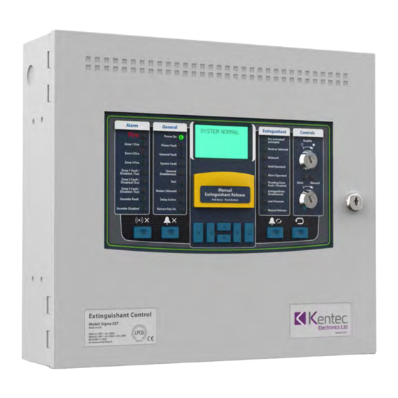
Overview 2 Section 2 Overview The figure below provides an overview Sigma ZXT Panel hardware. Figure 2-1 Compact Panel Features Alarm General Extinguishant Controls Pre-activated/ Enable Power On Activated Zone 1 Fire Power Fault Reserve Selected Zone 2 Fire General Fault... - Page 9 8. 2.6A Power supply 3. Enclosure hinge points (x2) 9. Mini USB connection 4. Enclosure back-box 10. Memory lock toggle switch 5. Enclosure cable entry points (knock-outs) 11. Reset micro-switches 6. Control Panel wiring terminals Man-1451 Rev.03 Sigma ZXT Product Manual...
- Page 10 5. Liquid Crystal Display (LCD) 15. Manual Release 6. Extinguishant status LED indicators 16. Panel enclosure lock 7. Control key-switches 8. Silence buzzer push-button 9. Silence Alarm button 10. Lamp Test and menu exit push-button Man-1451 Rev.03 Sigma ZXT Product Manual...
- Page 11 8. 5.25A Power supply (behind controls fascia) 3. Enclosure hinge points (x2) 9. Mini USB connection 4. Enclosure back-box 10. Memory lock toggle switch 5. Enclosure cable entry points (knock-outs) 11. Reset micro-switches 6. Control Panel wiring terminals Man-1451 Rev.03 Sigma ZXT Product Manual...
-
Page 12: Panel Installation
Thread external cabling into the enclosure and make connections to Control Panel terminals. Place standby batteries in base of enclosure and make connections. Apply mains power. Configure. Test installation. Man-1451 Rev.03 Sigma ZXT Product Manual... -
Page 13: Fascia Panel/Pcb Assembly Removal
1.Disconnect the DC supply to the fascia PCB by removing the pluggable connector mounted as shown in figure 3-1 Figure 3-1 Disconnect DC Supply 2.Disconnect the 14-way PSU monitoring ribbon cable from the Fascia PCB as shown in figure 3-2. Figure 3-2 Disconnect 14-Way Cable Man-1451 Rev.03 Sigma ZXT Product Manual... - Page 14 3-3. Figure 3-3 Remove Fascia Plate 4.Store the fascia plate in safe location until required. 5.To refit the fascia plate follow steps 1 to 3 in reverse. Man-1451 Rev.03 Sigma ZXT Product Manual...
-
Page 15: Mounting The Panel
External cabling should enter the control panel through suitable cable glands fitted in the knock-outs provided. Note: Enclosures vary. Figure 3-4 and Figure 3-5 show enclosure back box dimensions and fixing centres. Figure 3-4 XM2 Back Box Dimensions (mm). Drawing Not to Scale. 365.8 315.8 29.0 Man-1451 Rev.03 Sigma ZXT Product Manual... - Page 16 Panel Installation 3 Figure 3-5 XM3 Back Box Dimensions (mm) Drawing Not to Scale. 365.8 315.8 29.0 Man-1451 Rev.03 Sigma ZXT Product Manual...
-
Page 17: Control Panel Fascia Wiring
PCB. Wiring must not go across the front of the circuit board plate or between the plate and the circuit board. Figure 3-6 Wiring practice CORRECT INCORRECT INCORRECT Man-1451 Rev.03 Sigma ZXT Product Manual... -
Page 18: Electrical Connections
Important! To maintain continuity of Earth, a wire is provided connected between the enclosure earth terminal block (found on the inside rear of the enclosure back-box) and mains Earth. This connection must be maintained and in place prior to panel operation. Man-1451 Rev.03 Sigma ZXT Product Manual... -
Page 19: Power Supply
Fault monitoring of the power supply is provided by an 14-way IDC cable harness between the power supply and the main Panel PCB. Sigma ZXT is offered in two enclosure versions. The XM2 version accommodates 2 x 7Ah SLA batteries. The XM3 version can accommodate up to 2 x 18Ah SLA batteries. -
Page 20: Bs5839 Detector Removal
Part No. K14060 Intrinsically Safe (I.S.) Detection Zones Sigma ZXT supports the use of I.S. barriers for connecting to intrinsically safe detection devices installed within haz- ardous areas. Important! Only I.S. certified detectors may be installed within hazardous areas and must be connected to the ZXT Control Panel through a compatible I.S. -
Page 21: Monitored Inputs
Panel Installation 3 Monitored Inputs Sigma ZXT is provided with many monitored inputs for the connection of external system accessories such as pres- sure switches, key-switches etc. Monitored inputs have same characteristics as detection zones and require 6K8Ω EOL resistors to monitor circuit integrity, i.e. - Page 22 Activation of the input will illuminate the "Low Pressure" LED and will flash the "Flooding Zone Fault/Disabled" The input can be configured for use with either Normally Open (Normal) or Nor- mally Closed (Inverted) Pressure Switches (see the Configuration section of this manual). Man-1451 Rev.03 Sigma ZXT Product Manual...
-
Page 23: Non-Monitored Inputs
Transparent panel. A transparent event will not be displayed on the panel fascia but will be logged in the event log i.e. could be used to monitor open and closed state of access doors. Man-1451 Rev.03 Sigma ZXT Product Manual... -
Page 24: Output Circuits
Sounder circuits Three fully monitored polarised conventional sounder circuits are provided on the Sigma ZXT, identified as S1, S2 and S3. S1 and S2 These are common alarm sounder outputs providing notification of an active fire condition on any of the detec- tion zones, notifying personnel of the need to evacuate the area. -
Page 25: Extinguishing Outputs
Extinguishing Outputs Sigma ZXT in its default configuration has one dedicated extinguishing output for activation of an extinguishing so- lenoid or igniting actuators. The output is rated at 1 Amp continuous operation or 3 Amps for a maximum of 50ms. -
Page 26: Solenoid Wiring
3 OR 4 ACTUATORS WIRED IN SERIES (MAXIMUM OF 4) EXT1 or EXT2 (S2) 1 OR 2 ACTUATORS 2R2 2.5W RESISTOR WIRED IN SERIES FITTED IN SERIES WHEN 1 OR 2 ACTUATORS ARE USED EXT1 or EXT2 (S2) Man-1451 Rev.03 Sigma ZXT Product Manual... -
Page 27: Relay Outputs
Important! The default settings for relays ensure compliance to EN54-2 and EN12094 standards. Changing the functionality of the relay outputs will make the extinguishing system non-compliant with the above standards. Man-1451 Rev.03 Sigma ZXT Product Manual... -
Page 28: Aux 24V Dc Supply
RS485 Output An RS485 output is provided on the Sigma ZXT to allow connection of Status Indicators and Ancillary PCB’s. The RS485 output will support a combination of up to 7 x Status Indicators (addresses 1-7) and 7 x. Ancillary PCB’s (addresses 1 - 7). -
Page 29: Controls
Controls 4 Section 4 Controls Sigma ZXT combines LED status indications with a 128 x 64 pixel display to ensure status information is clear and concise. Figure 4-1 Control Panel fascia Alarm General Extinguishant Controls Pre-activated/ Enable Power On Activated... -
Page 30: Led Indications
(accompanied by the General Disablement This is a single LED indicating a generic sounder disablement which is complemented by further LED) detailed information on the LCD. LCD will indicate which sounder circuit(s) are disabled. Man-1451 Rev.03 Sigma ZXT Product Manual... -
Page 31: General Status Indications
Buzzer Silenced LED Status Description Steady amber Indicates that the panels buzzer has been silenced by pressing of the “Silence Buzzer” button. Silence buzzer function is only available during active alarm or fault events. Man-1451 Rev.03 Sigma ZXT Product Manual... -
Page 32: Extinguishing Status Indications
It will also illuminate if the “DIS EXT” input is active. Extinguishant Disabled LED Status Description Steady amber An amber LED indicating that the extinguishing function of the Panel has been disabled. Man-1451 Rev.03 Sigma ZXT Product Manual... - Page 33 Illuminates when the Manual Release circuit has been activated indicating a manual activation of the extinguishant release system. This is triggered by either the Manual Release button on the Panel fascia or status indicator or an Extinguishant Release Call Point connected to the Man Release input. Man-1451 Rev.03 Sigma ZXT Product Manual...
-
Page 34: Liquid Crystal Display (Lcd) Indications
Controls 4 Liquid Crystal Display (LCD) Indications Sigma ZXT features a 128 x 64 pixel LCD providing 8 lines x 21 characters enabling further alarm and fault indication to be displayed. The LCD has a 5 colour LED back-light which is used to provide easy visual status of access levels, fault or alarm conditions when set to Dynamic. - Page 35 EVENTS cONTROLS If an extinguishing release delay has been programmed the screen will flash red during the countdown process while displaying the countdown timer: ***extinguisher status*** 2nd stage ACTIVATED !! S TO RELEASE EVENTS Man-1451 Rev.03 Sigma ZXT Product Manual...
- Page 36 ***EXTINGUISHER STATUS*** DISCHARGING REMAINING EVENTS Note: The contrast of the LCD can be adjusted through the “User Settings” menu – Access Level 3. Man-1451 Rev.03 Sigma ZXT Product Manual...
-
Page 37: User Controls
Controls 4 User Controls Sigma ZXT user controls consist of an LCD navigation keypad, push buttons and key-switches. LCD Navigation Push Button The LCD Navigation Push Button Cluster enables the user to operate menu functions. Up and down can navigate the menus, left and right can be used to scroll through the various settings associated with a menu option. -
Page 38: Alarm Re-Sound
Pull Down - Push Button A yellow flap covers the Manual Release push-button to prevent accidental operation. To access the red push but- ton, pull down the flap. Figure 4-14 Manually Activating the Extinguishant Release Process Man-1451 Rev.03 Sigma ZXT Product Manual... -
Page 39: Control Key-Switches
Important! Switching between Auto and Manual modes can only be done using the same key-switch i.e. If manual mode is set using the control panel key-switch it can only be returned to auto using the same control panel key- switch, all other auto/manual key-switches on the system will be rendered non-functional. Man-1451 Rev.03 Sigma ZXT Product Manual... -
Page 40: Internal Indicators And Controls
Mini USB Connector This enables connection of a PC running LE2 configuration software. LE2 configuration software allows program- ming of panel settings as well as upload/download of config files and download of event logs. Man-1451 Rev.03 Sigma ZXT Product Manual... -
Page 41: Panel Configuration
Panel Configuration 5 Section 5 Panel Configuration Configuration and interrogation of the Sigma ZXT is performed using the menu structure that appears on the LCD and user Control buttons on the Panel fascia. Access Levels Sigma ZXT has three access levels:... -
Page 42: Access Level 2
The event log will store up to 999 events and once full will replace the oldest event with the newest. This screen also shows the alarm counter i.e. the number of alarms that have occurred on the panel. Man-1451 Rev.03 Sigma ZXT Product Manual... - Page 43 CIE ZONES.. bled states. When a detection zone is disabled the “General Disablement” LED and relevant zone disabled LED indicators illuminate. Details of the disablement event can be viewed on the LCD. Man-1451 Rev.03 Sigma ZXT Product Manual...
- Page 44 Note: To comply with the requirements of EN12094-1 2nd stage sounders S3 cannot be disabled unless the extinguishing system is also disabled. Therefore the option to disable Sounder 3 (S3) will only appear in this menu when the extinguishing system is disabled. Man-1451 Rev.03 Sigma ZXT Product Manual...
- Page 45 When an input is disabled the “General Disablement” LED will illumi- nate and any relay output programmed as “On General Disablement” will operate. Additional information relating to active disablements can be viewed on the LCD. Man-1451 Rev.03 Sigma ZXT Product Manual...
- Page 46 If manually turned off the countdown timer will disappear. Opens the Passcode login screen enabling the user to enter the Engineering Menu (access level ENGINEERING MENU.. 3) Passcode. Man-1451 Rev.03 Sigma ZXT Product Manual...
-
Page 47: Access Level 3 (Engineering)
The screen also provides the ability to install and remove devices from the sys- REMOTE BUS.. tem to prevent monitoring faults. For detailed information on connection installation of status indicators and ancillary boards to the ZXT, see Section 6. Man-1451 Rev.03 Sigma ZXT Product Manual... - Page 48 The setting can be toggled between YES and NO by FAULTS using the left/right buttons. Important! Compliance to EN54-2 requires this option to be set to YES. Default: YES Man-1451 Rev.03 Sigma ZXT Product Manual...
- Page 49 The setting of this feature has no effect at this time and will be implemented at a later date. Selecting this option displays the firmware screen. The screen displays the current firmware ver- FIRMWARE.. sion, it also shows the checksum associated with that firmware. Man-1451 Rev.03 Sigma ZXT Product Manual...
- Page 50 If configured to “AUTO” the Panel will automatically adjust its time setting in line with daylight DAYLIGHT SAVING saving changes. If set to “OFF” the Panel will require manual adjustment of its time setting when daylight saving changes are required. Default: AUTO Man-1451 Rev.03 Sigma ZXT Product Manual...
- Page 51 German, French LANGUAGE etc. The Local language will be specified at time of order. Left/right buttons can be used to select between English and Local options. Man-1451 Rev.03 Sigma ZXT Product Manual...
- Page 52 VERIFY DELAY The left/right buttons can be used to adjust the setting, this can be OFF or can be set between 5 and 30 secs in 5 sec increments. Default: OFF Man-1451 Rev.03 Sigma ZXT Product Manual...
- Page 53 If a fault exists on the hold input circuit the Panel will indicate a fault condition only. The extin- guishing system will continue to operate as normal. Important! Compliance to EN12094-1 requires this option to be set to HOLDS ALSO. Default: HOLDS ALSO Man-1451 Rev.03 Sigma ZXT Product Manual...
- Page 54 Important! If using the ZXT with Sigma SI status indicators the delay time must be set to a mul- tiple of 5 i.e. 5s, 10s, 15s etc. as Sigma SI status indicators will not recognise delay settings that are not a multiple of 5. Default: 30s Man-1451 Rev.03 Sigma ZXT Product Manual...
- Page 55 This delay will only start once the "Release Delay Auto" DELAY or the "Release Delay Manual" has completed. The left/right buttons are used to change the setting value from 0-60 secs. Default: 30s Man-1451 Rev.03 Sigma ZXT Product Manual...
- Page 56 PROG 1 or PROG 2 show on the second line. To enter a text description use the left and right arrow keys to move along the line and the up and down arrow keys to scroll through the letter selection. Man-1451 Rev.03 Sigma ZXT Product Manual...
- Page 57 If the Sounders have been silenced, the ZXT can be configured to ensure the Sounders resound if another alarm is activated in a different zone. RESOUND DIFF ZONE Use the left/right buttons to toggle the setting between “ON” and “OFF”. Default: ON Man-1451 Rev.03 Sigma ZXT Product Manual...
- Page 58 Panel Configuration 5 CLEAR EVENT LOG.. The Sigma ZXT is provided with an event log which records all events that occur on the Panel along with a time and date stamp. This provides a history of the Panels changes, activations, faults etc.
-
Page 59: Connection To Le2
USB A to USB Type B micro lead Figure 5-3 ZXT Connection to PC Micro USB Type B USB A Sigma ZXT To request an LE2 account or access to the ZXT database contact Kentec Tech Support. Man-1451 Rev.03 Sigma ZXT Product Manual... -
Page 60: Adding/Removing Status Indicators & Ancillary Boards
Sigma ZXT/XT Status Indicators and Ancillary Boards can be connected to ZXT Extinguishing Control Panels to ex- pand the performance and functionality of the system. A single Sigma ZXT Panel can support up to 7x Status Indicators and 7x Ancillary Boards, connected to the RS485 data bus. - Page 61 ZXT panel SI Bus which has not yet been regis- UNEXPECTED tered on the panel. Unexpected devices will be indicated as ageneral fault on the ZXT panel. Indicates a device has been removed or is no MISSING longer communicating with the system. Man-1451 Rev.03 Sigma ZXT Product Manual...
- Page 62 The status will change to OPERATIONAL in the status line and the graphic symbol for this address will change to □. The status LEDs should display their normal state and any buzzers will stop sounding. Complete this for all unexpected devices until all devices are logged on to the panel. Man-1451 Rev.03 Sigma ZXT Product Manual...
-
Page 63: Removing A Status Indicator
The following instructions detail how to remove a Status Unit from a ZXT system, this process is the same for both Sigma ZXT and Sigma XT Status Indicators. Important! For safety reasons power must be removed from the ZXT control panel before carrying out any modifi- cations to an extinguishing control system. -
Page 64: Adding An Ancillary Board To A Zxt
PROG I/P SETTINGS.. BACK goto menu 4. In the CONNECTED DEVICES screen, select the REMOTE BUS option to open the REMOTE BUS STATUS screen. Figure 6-9 Remote Bus ****connected devices**** >remote bus.. BACK goto menu Man-1451 Rev.03 Sigma ZXT Product Manual... - Page 65 The status will change to OPERATIONAL in the status line and the graphic symbol for this address will change to . Complete this for all unexpected devices until all devices are logged on to the panel. Man-1451 Rev.03 Sigma ZXT Product Manual...
-
Page 66: Removing An Ancillary Board
4. To remove the device from the ZXT configuration press the enter button (UNINSTALL) the status line for this address will show none and the graphical status icon will show. 5. The device has now been removed from the system and any associated faults will have cleared. Man-1451 Rev.03 Sigma ZXT Product Manual... -
Page 67: Maintenance & Assistance
Maintenance & Assistance Sigma ZXT control panels do not require any specific maintenance but should the control panel become dirty it can be wiped over with a barely damp cloth. Detergents or solvents should not be used to clean the panel and care must be taken that water does not enter the enclosure. -
Page 68: Repair Warranties
Failure to supply the required information will result in the returned items being quarantined for a period not exceed- ing 60 days. If the items are not identified within 60 days of receipt, then Kentec Electronics Ltd. reserves the right to dispose of these items or return them. -
Page 69: Lcd Menu Structure
The following diagrams provide an overview of the LCD menu structure. Panel functions are shown throughout Access Levels 1, 2 and 3. Figure 7-1 Access Level 1 PANEL START-UP SYS FLT (SAFE MODE) ACCESS LEVEL 1 SYSTEM STATUS EVENTS ACTIVE EVENTS SUMMARY CONTROLS PASSCODE ENTRY Man-1451 Rev.03 Sigma ZXT Product Manual... - Page 70 SOUNDER 1: ENABLED/DISABLED SOUNDER 2: ENABLED/DISABLED EXTRACTOR FAN RELAYS.. EXTRACTOR FAN: ON/OFF FIRE RELAY: ENABLED/DISABLED LOGOUT FAULT RELAY: ENABLED/DISABLED RELEASE RELAY: ENABLED/DISABLED ENGINEER PASSCODE ENTRY MODE RELAY: ENABLED/DISABLED HOLD RELAY: ENABLED/DISABLED ABORT RELAY: ENABLED/DISABLED Man-1451 Rev.03 Sigma ZXT Product Manual...
- Page 71 RELEASE DELAY AUTO: 0 TO 60s RELEASE DURATION: 60S TO INFINITE EXT 1 RELEASE TIME: 60S TO INFINITE EXT 2 RELEASE TIME: 60S TO INFINITE EXT 2 RELEASE DELAY: 60S TO INFINITE CALIBRATE EXT: CALIBRATE EXT1/CALIBRATE EXT2 Man-1451 Rev.03 Sigma ZXT Product Manual...
- Page 72 SILENCEABLE: YES/NO RESOUND DIFF ZONE: ON/OFF PANEL SOUNDER 2.. RING: STEADY/PULSE 1/PULSE 2/PULSE 3/OFF SILENCEABLE: YES/NO RESOUND DIFF ZONE: ON/OFF CLEAR EVENT LOG.. SERVICE DUE DATE.. YEAR MONTH MANAGE SITE DATA.. LOGOUT.. DIAGNOSTICS INFO.. Man-1451 Rev.03 Sigma ZXT Product Manual...
-
Page 73: Specification
S420 (2.6A) <200mV peak to peak @ rated volt- S406 (5.25A) age. Battery type S420 (2.6A) 7Ah: Yuasa NP7-12 S406 (5.25A) 12Ah: Yuasa NP12-12 Larger enclosure required when 17Ah: using 12/17Ah bat- Yuasa NP17-12 teries. Man-1451 Rev.03 Sigma ZXT Product Manual... - Page 74 Zone quiescent current S420 (2.6A) / S406 0mA minimum, (5.25A) PSU 2mA maximum Terminal capacity S420 (2.6A) / S406 0.5mm2 to 2.5mm2 (5.25A) PSU solid or stranded wire Man-1451 Rev.03 Sigma ZXT Product Manual...
- Page 75 Head removal condition S420 (2.6A) / S406 15.5 to 17.5 V +/- (5.25A) PSU Cabling S420 (2.6A) / S406 FP200 or equiva- (5.25A) PSU lent (max. capaci- tance 1uF. Max inductance 1 milli- henry) Man-1451 Rev.03 Sigma ZXT Product Manual...
-
Page 76: Environmental
Important! This Control Panel is environmental class A and is designed for indoor use only. Operation outside these parame- ters may render the equipment unsafe. Operating temperature range -10 to +40°C (95% relative humidity, non-condensing) Storage temperature range -20 to + 80°C Ingress protection IP30 Man-1451 Rev.03 Sigma ZXT Product Manual... -
Page 77: Battery Calculation
I1 = battery standby load in amperes I2 = battery alarm load in amperes D = battery de-rating factor (usually assumed at 1.75). This allows for the inefficiency of the battery under high load conditions Man-1451 Rev.03 Sigma ZXT Product Manual... -
Page 78: Glossary
Sounder 1 Sounder 2 Sounder 3 Schottky diode A diode which has a low forward voltage drop and a very fast switching action. Silence Sealed Lead Acid. Switch Watchdog System monitoring (safe mode). Zone Man-1451 Rev.03 Sigma ZXT Product Manual...
Need help?
Do you have a question about the Sigma ZXT and is the answer not in the manual?
Questions and answers