Advertisement
Table of Contents
- 1 Table of Contents
- 2 Features
- 3 Definitions
- 4 Mytechnician
- 5 Installation/Operation/Maintenance
- 6 Startup / Checkout
- 7 Sequence of Operation
- 8 Maintenance
- 9 Appendix A - Typical Boiler Wiring
- 10 Appendix B - Typical Furnace Wiring
- 11 Appendix C - Typical Thermostat Wiring
- 12 Appendix D - Typical Air Input Wiring
- Download this manual
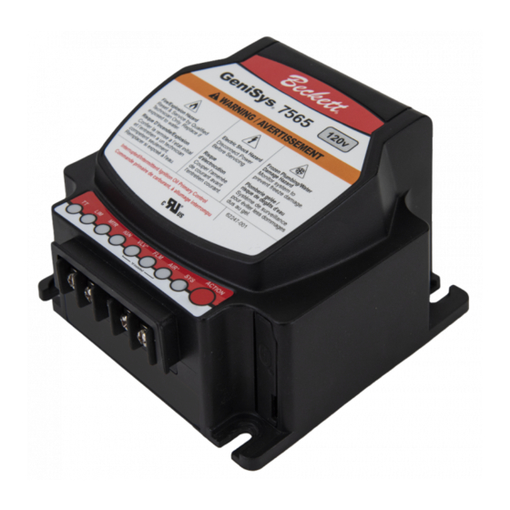
GENISYS
120v Advanced Burner Controls
DESCRIPTION / APPLICATIONS
The Beckett GeniSys® Advanced Burner Control is a 120 Vac
primary safety control for residential and light commercial oil
burners used in boiler, furnace, and water heater applications
having firing rates less than 20 GPH.
The GeniSys is used with a suitable cad cell flame sensor to control
the oil burner motor, igniter, and optional solenoid valve. It has 24
Vac thermostat terminals compatible with both mechanical and
many power stealing thermostats. It can also provide interrupted
or intermittent duty ignition.
7565 & 7585
®
Advertisement
Table of Contents

Related Manuals for Beckett GENISYS 7565


Summary of Contents for Beckett GENISYS 7565
- Page 1 ® 120v Advanced Burner Controls DESCRIPTION / APPLICATIONS The Beckett GeniSys® Advanced Burner Control is a 120 Vac primary safety control for residential and light commercial oil burners used in boiler, furnace, and water heater applications having firing rates less than 20 GPH.
-
Page 2: Table Of Contents
◦ Table of Contents Blocked Vent (BV) - The control will not start a heat cycle unless the switch is closed. The control will Recycle if the switch opens after a successful Content Page ignition trial period. It must be closed during burner Features cycles. - Page 3 Limit (red) Motor L2 (white) Reserved for Future Use L2 (Igniter) Valve* CAD Cell L2 (Valve)* CAD Cell Igniter Caution: if replacing a non-Beckett control, these colors may vary. Asterisk = If installed 120v GeniSys Control Installation and Operation Manual...
-
Page 4: Installation/Operation/Maintenance
Installation/Operation/ Do Not Use This Maintenance Control in an Application that is Not Within the Ratings Listed in This Section. Improper Control Professional Operation May Result. Service Required Incorrect installation or misuse of Electrical Ratings this control could result in severe personal injury, death, or Power: substantial property damage from... - Page 5 Fire or Explosion Incorrect Wiring Hazard Will Result in Improper Control Operation Can cause severe injury, death, or • property damage. The control wiring label colors may not match the wire colors of the burner or • The control can malfunction if it gets other manufacturers’...
-
Page 6: Startup / Checkout
Startup / Checkout 3. Burner must not start. Verify that the SYS Fire Hazard light is green, FLM light is yellow, and that the control remains in Standby mode. Reset and Service by Qualified 4. End the call for heat and remove the cad Technician only. -
Page 7: Sequence Of Operation
Recycle Delay turning on the oil solenoid valve for the programmed time. This feature requires either a Beckett Clean-Cut pump or an 1 = only if air switch is installed external valve. 2 = only if valve installed Trial For Ignition (TFI): If used, the oil Lockout: The control has shut down for solenoid valve is energized. - Page 8 ACTION Button Operation 2. Initiate a call for heat. Table 2 explains what action the control will take 3. After the burner starts, press and hold the when the button is pressed for different lengths of ACTION button for 15 seconds until the time during the various burner operating states.
-
Page 9: Maintenance
Resetting From Restricted or Hard Lockout Disable Function ◦ Fire, Smoke & Any time the burner is running, press and Fuel Leak Hazard hold the ACTION button to disable the Before starting or resetting the burner. The burner will remain off as long as control from restricted lockout state, the button is held. -
Page 10: Appendix A - Typical Boiler Wiring
Appendix - B Typical Furnace Wiring Appendix A - Typical Boiler Wiring Figure 6 – 7565 (for replacement of R8184G, R7184A) Figure 3 – 7565 (for replacement of R8184G) No valve-on or motor-off delay No valve-on delay, no motor-off delay. BOILER CONTROL WHITE THERMOSTAT... -
Page 11: Appendix C - Typical Thermostat Wiring
Appendix C - Thermostat Wiring Requiring a Common (C) Terminal Figure 10 - Thermostat Wiring with External Transformer Figure 9 - 3-Wire Thermostat For example, an air conditioning transformer. 120 VAC Connector Pins Connector Pins L1 (1) L1 (1) LIM (2) LIM (2) L2 (3) L2 (3) - Page 12 The R. W. BECKETT CORPORATION (“Beckett”) warrants to persons who purchase its “Products” from Beckett for resale, or for incorporation into a product for resale (“Customers”), that its equipment is free from defects in material and workmanship. To qualify for warranty benefits, products must be installed by a qualified service agency in full compliance with all codes and authorities having jurisdiction, and used within the tolerances of Beckett’s defined product specifications.
Need help?
Do you have a question about the GENISYS 7565 and is the answer not in the manual?
Questions and answers