Table of Contents
Advertisement
PARTS & ACCESSORIES
Description / Applications
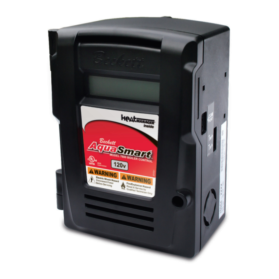
The Beckett AquaSmart™ is an advanced boiler control designed for use on
residential and light commercial boiler systems. All models include the option of
enabling Beckett HeatManager™ dynamic temperature reset that, when selected,
provides up to 20% fuel consumption savings. The control includes a backlit LCD
digital display with touch pad to easily program temperature limits, differentials,
and other advanced options. The AquaSmart™ also has memory storage of
system history for help with diagnostics and troubleshooting.
Advertisement
Table of Contents

Related Manuals for Beckett AQUASMART 7600


Summary of Contents for Beckett AQUASMART 7600
- Page 1 PARTS & ACCESSORIES Description / Applications The Beckett AquaSmart™ is an advanced boiler control designed for use on residential and light commercial boiler systems. All models include the option of enabling Beckett HeatManager™ dynamic temperature reset that, when selected, provides up to 20% fuel consumption savings. The control includes a backlit LCD digital display with touch pad to easily program temperature limits, differentials, and other advanced options.
-
Page 2: Table Of Contents
D. Temperature Low Limit Differential ... Programming Additional Options ... 26 A. Changing the Heat Manager Settings ... B. Viewing the Boiler Cycle History ... C. Changing the Circulator Settings ... D. Changing Domestic Hot Water Priority (DHWP) Setting ... -
Page 3: Technical Specifi Cations
Figure 1 - Getting to know the AquaSmart 7600 Series Control Electrical Shock Hazard The AquaSmart control should only be operated with the door attached and securely closed. Communication Port Clamping Screw For Sensor Power Disconnect Switch (Optional) Technical Specifi cations... -
Page 4: Installation
Table 1. There are two basic methods for mounting the AquaSmart to the boiler as outlined in Figure 3. Sensor/Immersion Well Mounting – This is the most common method. If the existing well is not... -
Page 5: Aquasmart Models And Cross-Reference Guide
Carefully follow these guidelines and the directions provided by the manufacturer of the control being replaced. Note: Beckett assumes no liability for incorrect installation or replacement. Table 1b - Functional Replacement (Advanced Wiring Needed) - Page 6 Table 1b (continued from previous page) Beckett Honeywell Notes Replacement 7600A or 7600B L4081A/B (Based on System Remove switching relay, if used, from the system when replacing the L4081 or L6081. L6081A/C Voltage Make sure 7600 outputs do not exceed 7.4A @ 120 VAC. 7600 outputs are not rated for 240 VAC.
-
Page 7: Removing The Control To Be Replaced
See Figure 10. Note: The sensor is not tested and approved for being mounted to the outside of a pipe. It is for use in immersion wells only. Figure 4b - Strain Relief Sensor connects to Beckett AquaSmart Brass Fitting... -
Page 8: Installing The 2-In-1 Sensor
Failure to secure an electrical bond will result in the AquaSmart locking out and displaying, “LOCKOUT - LOW WATER”. -
Page 9: 2-In-1 Installation Instructions
Apply pipe sealant to the 2-in-1 sensor threads and install it securely into the port. BECKETT RECOMMENDS ONLY TO USE TEFLON TAPE OR RECTORSEAL NO. 5 PIPE SEALANT. Tighten with 1-1/8” open end or box wrench. Pipe wrenches, pliers, and adjustable wrenches will damage/round-off the hex. -
Page 10: Installing The Aquasmart Control
Installing the AquaSmart Control (Refer back to Figure 3 for appropriate mounting method). Immersion Well or 2-in-1 Sensor Mount the control by aligning the 7/8” diameter hole (found on back) around the mating feature of the immersion well or 2-in-1 sensor and press into place. -
Page 11: Wiring The Aquasmart Control
ZR input may not be recognized. AquaSmart Boiler Control Manual 24-volt supply for operating other 24 VAC equipment on the boiler. IMPORTANT: TO PREVENT DAMAGE TO THE CONTROL, DO NOT OVERLOAD THE TRANSFORMER. The AquaSmart is equipped with a 30VA transformer. -
Page 12: Water Flow
Figure 12 - 7600A/B single-zone connections with or without a tankless coil Water Flow: Control Wiring: 1. Set “DHWP OFF” (default, see programming section for instructions) 2. Set “C1 on TT” (default, see programming section for instructions) NEUTRAL 120 VAC FIELD/MFR. - Page 13 3. Circulator-on and -off delays will only affect zone 1 C1 C2 ZC ZR B1 B2 CIRCULATOR 120 VAC NEUTRAL WHITE 120 VAC BLACK FIELD/MFR. SUPPLIED SERVICE SWITCH AquaSmart Boiler Control Manual VENT SEPARATOR EXPANSION TANK COLD WATER INLET WHITE ZONE LOW VOLTAGE THERMOSTAT...
- Page 14 Figure 13 (continued) - 7600A/B multi-zone connections with or without a tankless coil ◄ CONTINUED FROM PREVIOUS PAGE Control Wiring (Option 2): Circulator-On Delay on All Zones 1. Set “DHWP OFF” (default, see programming section for instructions) 2. Set “C1 on ZR” (see programming section for instructions) 3.
- Page 15 5. Ensure there are no jumpers between the terminals of the zone valves. C1 C2 ZC ZR B1 B2 NEUTRAL WHITE 120 VAC BLACK FIELD/MFR. SUPPLIED CIRCULATOR SERVICE 120 VAC SWITCH AquaSmart Boiler Control Manual VENT SEPARATOR GENERAL CIRCULATOR EXPANSION TANK COLD WATER INLET ZONE 1 LOW VOLTAGE...
- Page 16 Figure 14 (continued) - 7600A/B alternate multi-zone connections with or without a tankless coil ◄ CONTINUED FROM PREVIOUS PAGE Control Wiring (Option 2): 7600A only 1. Set “DHWP OFF” (default, see programming section for instructions) 2. Set “C1 on TT” (default, see programming section for instructions) 3.
- Page 17 2. Set “C1 on TT” (default, see programming section for instructions) 3. Circulator-on and -off delay will only affect zone 1. NEUTRAL WHITE 120 VAC BLACK FIELD/MFR. CIRCULATOR SUPPLIED SERVICE SWITCH AquaSmart Boiler Control Manual VENT SEPARATOR EXPANSION TANK COLD WATER INLET WHITE ZONE LOW VOLTAGE...
- Page 18 Figure 16 - 7600A/B multi-zone connections with Indirect Domestic Hot Water (DHW) Water Flow: * additional zones can be added by duplicating the plumbing and wiring of zone 3. VENT SEPARATOR INDIRECT ZONE EXPANSION TANK COLD WATER INLET HEATING HEATING HEATING ZONE ZONE...
- Page 19 CIRCULATOR 120 VAC NEUTRAL WHITE 120 VAC BLACK FIELD/MFR. SUPPLIED SERVICE SWITCH AquaSmart Boiler Control Manual * Additional zones can be added by duplicating LIMIT CONTROL 7600A: 120 VAC BURNER OR GAS IGNITION SYSTEM 7600B: 24 VAC GAS IGNITION SYSTEM the plumbing and wiring of zone 3.
- Page 20 Figure 16 (continued) - 7600A/B multi-zone connections with Indirect Domestic Hot Water (DHW) ◄ CONTINUED FROM PREVIOUS PAGE Control Wiring (Option 2): Circulator-On Delay on All Zones 1. Set “DHWP OFF” (default, see programming section for instructions) 2. Set “C1 on ZR” (see programming section for instructions) 3.
- Page 21 3. Circulator-on and -off delay will only effect DHW zone. 4. A call for heat on TT (from the DHW zone) will change boiler set point to the high limit. All other zones will heat to the reset temperature determined by the HeatManager.
- Page 22 Figure 17 - 7600A/B alternate multi-zone connections with Indirect Domestic Hot Water (DHW) Water Flow: GENERAL CIRCULATOR VENT SEPARATOR DHW ZONE 24 VAC ZONE VALVE INDIRECT ZONE EXPANSION TANK COLD WATER INLET * Additional zones can be added by duplicating the plumbing and wiring of zone 3, adding additional transformers as needed.
- Page 23 FIELD/MFR. SUPPLIED SERVICE SWITCH GENERAL CIRCULATOR CIRCULATOR 120 VAC AquaSmart Boiler Control Manual * Additional zones can be added by duplicating the plumbing and wiring of zone 3, adding additional transformers as needed. DHW ZONE 24 VAC ZONE VALVE Honeywell...
- Page 24 Figure 17 (continued) - 7600A/B alternate multi-zone connections with Indirect Domestic Hot Water (DHW) ◄ CONTINUED FROM PREVIOUS PAGE Control Wiring (Option 2): 7600A only 1. Set “DHWP on ZR” (see programming section for instructions) 2. Set “C1 on BOTH” (see programming section for instructions) 3.
-
Page 25: Programming Basic Functions
Press the “ENTER (RESET)” The control will ask you to confi rm the setting with AquaSmart Boiler Control Manual the following screen: Press “CANCEL (BACK)” B. Temperature Low Limit In any mode or screen other than an OPTION sub-... -
Page 26: Temperature Low Limit Differential
HI, MED, and LOW. See “HeatManager Technology” section for an explanation of the effi ciency settings. Press B. Viewing the Boiler Cycle History In any mode or screen other than an OPTION sub- menu, press the The following screen will be displayed: ... -
Page 27: Changing The Circulator Settings
CFH = the call for heat (from T-T or ZR) was satisfi ed HL = the boiler water temperature reached the high operating limit. LL = the boiler water temperature reached the low limit plus low differential. Lockout reasons (see Lockout Troubleshooting section for more details): SENSOR ERR, SELF-CHECK, CANCEL C. -
Page 28: Changing Domestic Hot Water Priority (Dhwp) Setting
The DELAY ON time can be selected to delay the response of the control when the boiler water returns to a suffi cient level. The RESET function can be set to AUTO or MAN... - Page 29 If the RESET function has been selected, press “ENTER (RESET)” to change between MAN and AUTO. Press “CANCEL (BACK)” previous screen. Press “CANCEL (BACK)” to exit LWCO menu. AquaSmart Boiler Control Manual “▲” “ENTER to go to the...
-
Page 30: Aquasmart Operation
See lockout section for more information. ○ Circulator and ZC are turned on to help prevent system freeze- up by circulating the boiler water to all zones. ○ If DHWP is set on T-T and there is a T-T call for heat, ZC is held off for up to 20 minutes to give the DHW zone priority. -
Page 31: How A Boiler Control Works
How a Boiler Control Works Figure 19 - Cold Start Operation (Low Limit ► OFF) Figure 20 - Warm Start Operation (Low Limit ► ON) Low Temperature Differential (Adjustable 10° to 45°F) Shuts burner off when temperature rises to the LOW LIMIT DIFFERENTIAL setting. -
Page 32: Display Boiler Status Mode
The control will resume normal operation once the CANCEL (BACK) button is released. HeatManager Technology The Beckett AquaSmart comes equipped with the Department of Energy (DOE) 2012 compliant Heat Manager load-matching energy saving algorithm. The Heat Manager saves fuel by dynamically changing the temperature high operating limit to the minimum temperature necessary to meet the heating demand. -
Page 33: Final Checklist
□ A record has been made of all service work and all temperature control settings and optional functions. Attach a label or tag to the boiler for future reference. □ The AquaSmart Installation Manual is left at a suitable location near the boiler for future reference and the equipment owner is informed of this. - Page 34 Notes Section...
-
Page 35: Mounting Template
THIS END UP Mounting Template Use self-drilling screws supplied in the 7600RMU Remote Mount Kit -or- Drill 0.110” diameter holes AquaSmart Boiler Control Manual... -
Page 36: Limited Warranty Information
The R. W. BECKETT CORPORATION (“Beckett”) warrants to persons who purchase its “Products” from Beckett for resale, or for incorporation into a product for resale (“Customers”), that its equipment is free from defects in material and workmanship. To qualify for warranty benefi ts, products must be installed by a qualifi...
Need help?
Do you have a question about the AQUASMART 7600 and is the answer not in the manual?
Questions and answers