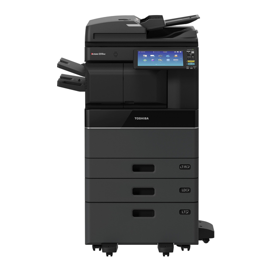
Toshiba e-STUDIO2010AC User Manual
Sys board diagnosis tool
Hide thumbs
Also See for e-STUDIO2010AC:
- Imaging manual (340 pages) ,
- Management manual (32 pages) ,
- Operator's manual (32 pages)
Summary of Contents for Toshiba e-STUDIO2010AC
- Page 1 SYS Board Diagnosis Tool User’s Guide e-STUDIO2010AC/2510AC e-STUDIO2515AC/3015AC/3515AC/4515AC5015AC e-STUDIO2018A/2518A/3018A/3518A/4518A/5018A e-STUDIO5516AC/6516AC/7516AC e-STUDIO5518A/6518A/7518A/8518A Version 01 10/2021...
-
Page 2: Table Of Contents
Table of Contents Precautions ..........................3 Introduction ........................4 Target Models ........................4 USB Memory Requirements .................... 4 USB Advanced Preparation ..................... 5 Procedure to Use the Diagnostic Tool ................5 Procedure when the Result is NG ................. 12 TABLE 1 - Correspondence table when NG occurs ..........13 Procedure when the result is OK .................. -
Page 3: Precautions
Precautions • Use the System Board Diagnostic tool prior to using the Logic Board Diagnostic tool. • This tool is only for use with the models listed in ‘Target Models’ below. It will not work on models that are not listed. •... -
Page 4: Introduction
• A call for service related to the HDD has occurred. • AN “F” series error has occurred. Target Models This tool can only be used on the following models. It does not work properly on any other models. • e-STUDIO2010AC/2510AC • e-STUDIO2015C/2515AC/3015AC/3515AC/4515AC/5015AC • e-STUDIO2018A/2518A/3018A/3518A/4518A/5018A • e-STUDIO5516AC/6516AC/7516AC •... -
Page 5: Usb Advanced Preparation
USB Advanced Preparation Unzip the tool file (ttecbackupflashrom_S18_SYS_Ver01.zip) and store the tool file under the root of the USB device as indicated below. (USB) ┗ ttecbackupflashrom ┣ bzImage ┣ bzImage.sig ┣ grub.cfg ┣ grub.cfg.sig ┣ initrd.gz ┣ initrd.gz.sig ┣ VerXX * jasdat ┣... - Page 6 4. Remove the short pin attached to CN106 of the SYS Board and then insert the short pin on one side of CN106 as shown in the figure below. 5. Insert the USB memory containing the Diagnostic tool into the usb port locate on the left-side of Control Panel or the upper right side of the machine (the USB memory insertion slot location differs depending on the model).
- Page 7 9. When the tool diagnosis has complete, the judgment of OK or NG as shown in the example figure below is displayed on the LCD of the Control Panel. HDD Information HDD Information RESULT : NG Judgement result 10. When the result is displayed and the buzzer sounds, press and hold the power button for approximately 5 seconds to turn the power OFF.
- Page 8 12. Replace the CN106 short pin removed in Step 4 above to its original position. Caution: If the CN106 short pin is not returned to its original position, the screen shown below will be displayed at startup and normal startup will not be possible. Replace the short pin correctly and restart the machine.
- Page 9 The flow chart below shows the procedure for using the Diagnostic tool.
- Page 10 Check Flow A...
- Page 11 Check Flow B...
-
Page 12: Procedure When The Result Is Ng
Procedure when the Result is NG When NG occurs, a screen like the one shown below is displayed on the Control Panel. 1. Check the item(s) in red. 2. Refer to the Correspondence table (below) and take the corrective action. The inspection number and item results are displayed on the Control Panel. - Page 13 TABLE 1 - Correspondence table when NG occurs Inspection item Inspection result Correspondence 01 Board Type Replace the SYS board. 02 CPU Clock Replace the SYS board. 03 FROM Replace the SYS board. Main Memory Step 1.Check the installation status of the Size NG <2GB>...
- Page 14 Inspection item Correspondence Inspection result NG [LINK DOWN] SATA I/F & Step 1. Check the installation status of the NG [SPD] SMART HDD harness. Step 2. Replace the HDD harness. Step 3. Replace the HDD. Step 4. Replace the SYS board. NG [SMART] Replace the HDD.
- Page 15 Inspection item Inspection result Correspondence Refer to C280 Troubleshoot of service NG <DF*1> manual and check each item. [C280] *2 Communication NG <DF*1> Step 1. Check if 24V supplied to the SYS [C290] *2 *1.Here shows board. the installed ⇒ If supplied, replace the SYS board. status of the DF Step 2.
-
Page 16: Procedure When The Result Is Ok
No. Inspection item Inspection result Correspondence 18 CPU FAN Step 1. Check if the fan is rotating properly. ⇒ If rotating, replace the SYS board. ⇒ If not rotating, go to Step 2. Step 2. Check the FAN connector (CN117). ⇒... - Page 17 TABLE 2- Correspondence Table when checking Options Inspection Option connect Inspection Correspondence Item status result PCIE ASIC1 DSDF OK? Step 1. Check the installation (If the DSDF unit connected. status of the DSDF I/F board. unit is Step 2. Replace the DSDF IF connected board.
- Page 18 Inspection Option connect Inspection Correspondence Item status result Two Fax boards USB FAX Step 1. Check if connectors connected [Fax2 detected] CN101 and CN103 are connected. ⇒ If not improve, go to Step 2. Step 2. Check and replace the related harness.
-
Page 19: When The Files Are Corrupted
Troubleshooting when the tool does not function When the tool does not function properly, check the following items. (1) When the USB memory is not recognized, or the file cannot be read. If the following screen is displayed, confirm the ‘Items to check’ below. Items to check ・... -
Page 20: When "Result : Usb Mount Ng" Is Displayed On The Control Panel
(3) When "RESULT : USB MOUNT NG" is displayed on the Control Panel If the following screen is displayed, confirm the following. Check if the USB memory mounting position is as shown in the figure below. Check if the connector mounting position (indicated by the red box) is as shown in the figure below.


