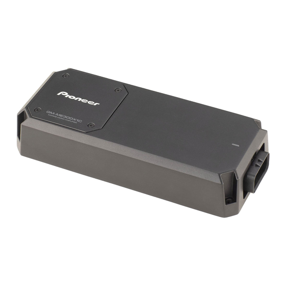
Summary of Contents for Pioneer GM-ME300X1C
- Page 1 Owner’s Manual Mode d’emploi Manual de instrucciones MARINE MONO AMPLIFIER AMPLIFICATEUR MONOBLOC MARIN AMPLIFICATEUR MONOAURAL MARINO GM-ME300X1C English Français Español...
-
Page 2: Information To User
Pioneer service company for after- sales service or questions you may have about the product. You may contact Pioneer directly Note as follows: Do not ship your unit in for repair... - Page 3 Use adequate tions not authorized in writing by Pioneer are gauge, marine grade electrical wire that has excluded from limited warranty coverage.
- Page 4 While this amplifier is designed to be water-re- sistant, it should never be submerged under water or subjected to high-pressure water bined or singular nominal impedance spray. less than 2 Install the amplifier in a dry and well-ventilated environment, where other equipment will not About the protection function interfere with it.
-
Page 5: Setting The Unit
(standard output of 500 mV), set to the What’s what NOR (normal) position. For use with an Top side RCA equipped Pioneer headunit with maximum output of 4 V or more, adjust 1 2 3 4 level to match that of the stereo output. - Page 6 Precise Frequency Selection Gain volume of this unit 0.5 V (Maximum preout level=2 V) Chart The numbers in the illustration correspond to the Step Number. No.11 No.7 No.15 No.19 Maximum preout level=4V No.3 Above illustration shows NOR (normal) gain No.1 No.21 setting.
- Page 7 Connecting the units Connection diagram WARNING Secure the wiring with cable clamps or adhe- sive tape. To protect the wiring, wrap sections in contact with metal parts in adhesive tape. Never cut the insulation of the power supply to feed power to other equipment. Current capacity of the wire is limited.
-
Page 8: Installation
If you lose the supplied tool, use a flat screw- Installation driver with a tip width of 3 mm or less as a substitute. Before installing the Max 3 mm (1/8 in.) WARNING To ensure proper installation, use the sup- Connections when using the plied parts in the manner specified. -
Page 9: Additional Information
Additional information supplied tapping screws (4 mm × 25 mm). Power source ...... 14.4 V DC (10.8 V to 15.1 V allowable) Grounding system ....Negative type Current consumption ..25 A (at continuous power, ② Average current consumption .......... 5.6 A (4 for one channel) 6.3 A (2 for one channel) - Page 10 Power output....... 300 W RMS × 1 Channel (at 14.4 V, 4 20 Hz to 240 Hz S/N ratio ......75 dBA (reference: 1 W into Accessories Power cable × 1 Speaker line input RCA cable × 1 Hexagonal wrench × 1 Mounting screw (4 ×...
- Page 11 PIONEER CORPORATION 28-8, Honkomagome 2-chome, Bunkyo-ku, Tokyo 113-0021, JAPAN PIONEER ELECTRONICS (USA) INC. P.O. Box 1540, Long Beach, California 90801-1540, U.S.A. TEL: (800) 421-1404 © 2020 PIONEER CORPORATION. <A1-000028-9L-A> UC <KNZZ20K>...
- Page 12 U.S.A. and Canada that fail to function properly under normal use due to a manufacturing defect when installed and operated according to the owner’s manual enclosed with the unit will be repaired or replaced with a unit of comparable value, at Pioneer’s option, without charge to you for parts or actual repair work.
- Page 13 Votre entreprise de services Pioneer autorisée - peut effectuer des réparations pour la plupart des produits électroniques automobiles/marins, des haut- parleurs et des accessoires et peut vous conseiller sur le choix d’autres options, selon le cas. Visitez le site Web de Pioneer, cliquez sur « Soutien », puis sélectionnez «...


