Advertisement
S
ervice
M anua l
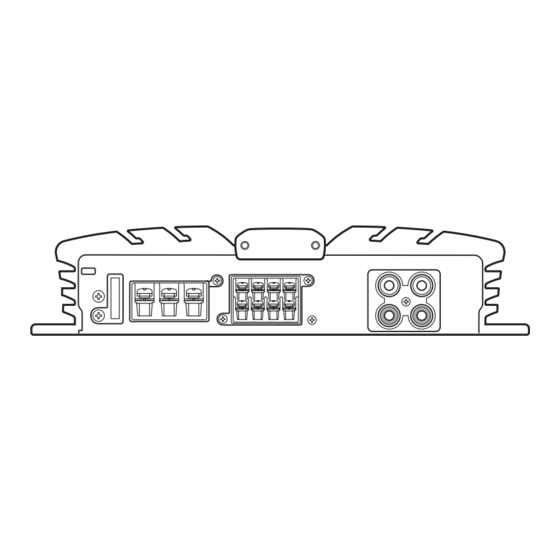
BRIDGEABLE POWER AMPLIFIER
GM-X422
GM-X322
CONTENTS
1. SAFETY INFORMATION ............................................1
2. EXPLODED VIEWS AND PARTS LIST .......................2
3. SCHEMATIC DIAGRAM .............................................6
4. PCB CONNECTION DIAGRAM ..................................8
1. SAFETY INFORMATION
This service manual is intended for qualified service technicians; it is not meant for the casual do-it-yourselfer.
Qualified technicians have the necessary test equipment and tools, and have been trained to properly and safely repair
complex products such as those covered by this manual.
Improperly performed repairs can adversely affect the safety and reliability of the product and may void the warranty.
If you are not qualified to perform the repair of this product properly and safely, you should mot risk trying to do so
and refer the repair to a qualified service technician.
UC model
CAUTION
This service manual is intended for qualified service technicians; it is not meant for the casual do-it-yourselfer.
Qualified technicians have the necessary test equipment and tools, and have been trained to properly and safely repair
complex products such as those covered by this manual.
Improperly performed repairs can adversely affect the safety and reliability of the product and may void the warranty.
If you are not qualified to perform the repair of this product properly and safely; you should not risk trying to do so
and refer the repair to a qualified service technician.
WARNING
Lead in solder used in this product is listed by the California Health and Welfare agency as a known reproductive toxi-
cant which may cause birth defects or other reproductive harm (California Health & Safety Code, Section 25249.5).
When servicing or handling circuit boards and other components which contain lead in solder, avoid unprotected skin
contact with the solder. Also, when soldering do not inhale any smoke or fumes produced.
PIONEER ELECTRONIC CORPORATION
PIONEER ELECTRONICS SERVICE INC.
PIONEER ELECTRONIC [EUROPE] N.V.
PIONEER ELECTRONICS ASIACENTRE, PTE.LTD. 501 Orchard Road, #10-00, Wheelock Place, Singapore 238880
C PIONEER ELECTRONIC CORPORATION 1998
4-1, Meguro 1-Chome, Meguro-ku, Tokyo 153-8654, Japan
P.O.Box 1760, Long Beach, CA 90801-1760 U.S.A.
Haven 1087 Keetberglaan 1, 9120 Melsele, Belgium
X1R/UC, ES, EW
X1R/UC
5. ELECTRICAL PARTS LIST ........................................12
6. ADJUSTMENT..........................................................14
7. GENERAL INFORMATION .......................................15
7.1 DISASSEMBLY ...................................................15
8. OPERATIONS AND SPECIFICATIONS.....................16
K-ZEU. JAN. 1998 Printed in Japan
ORDER NO.
CRT2167
Advertisement
Table of Contents

Related Manuals for Pioneer GM-X422


Summary of Contents for Pioneer GM-X422
-
Page 1: Table Of Contents
P.O.Box 1760, Long Beach, CA 90801-1760 U.S.A. PIONEER ELECTRONIC [EUROPE] N.V. Haven 1087 Keetberglaan 1, 9120 Melsele, Belgium PIONEER ELECTRONICS ASIACENTRE, PTE.LTD. 501 Orchard Road, #10-00, Wheelock Place, Singapore 238880 C PIONEER ELECTRONIC CORPORATION 1998 K-ZEU. JAN. 1998 Printed in Japan... -
Page 2: Exploded Views And Parts List
GM-X422, GM-X322 2. EXPLODED VIEWS AND PARTS LIST 2.1. PACKING Fig. 1 NOTE: Parts marked by “*”are generally unavailable because they are not in our Master Spare Parts List. Screws adjacent to mark on the product are used for disassembly. - Page 3 GM-X422, GM-X322 (2) CONTRAST TABLE GM-X422/X1R/UC, GM-X422/X1R/ES, GM-X422/X1R/EW and GM-X322/X1R/UC are constructed the same except for the following: Part No. GM-X422 GM-X322 Mark No. Symbol and Description X1R/UC X1R/ES X1R/EW X1R/UC Contain Box HHL0134 HHL0135 HHL0136 HHL0133 Carton HHG0134 HHG0135...
- Page 4 GM-X422, GM-X322 2.2. EXTERIOR Fig. 2...
- Page 5 See Contrast table (2) 42 Light Pipe Unit HXA0182 43 Special Red Battery Wire See Contrast table (2) (2) CONTRAST TABLE GM-X422/X1R/UC, GM-X422/X1R/ES, GM-X422/X1R/EW and GM-X322/X1R/UC are constructed the same except for the following: Part No. GM-X422 GM-X322 Mark No.
-
Page 6: Schematic Diagram
Note: When ordering service parts, be sure to refer to "EXPLODED VIEWS AND PARTS LIST" or "ELECTRICAL PARTS LIST". MOTHER PCB SPEAKER INPUT LEVEL UC and ES models only R469, 470 : GM-X322 only 10/50 VR452 : GM-X422 only BASS BOOST 10/50 LPF / HPF C851, 852 UC, ES : 100P EW : 470P... - Page 7 GM-X422, GM-X322 PRE DRIVER POWER AMP OVER CURRENT DETECTOR BUFFER AMP MUTE SWITCHING CONTROL ES and EW models only ES and EW models only HEK0015 15A GROUND WIRE BATTERY WIRE SYSTEM REMOTE OVER VOLTAGE POWER CONTROL / MUTE CONTROL PROTECTOR...
-
Page 8: Pcb Connection Diagram
GM-X422, GM-X322 4. PCB CONNECTION DIAGRAM NOTE FOR PCB DIAGRAMS 1. The parts mounted on this PCB include all necessary parts for several destination. MOTHER PCB For further information for respective destinations, be sure CORD ASSY to check with the schematic dia- gram. - Page 9 GM-X422, GM-X322 SIDE A ISOLATOR PCB Fig. 4...
- Page 10 GM-X422, GM-X322 MOTHER PCB ISOLATOR PCB...
- Page 11 GM-X422, GM-X322 SIDE B Fig. 5...
-
Page 12: Electrical Parts List
GM-X422, GM-X322 5. ELECTRICAL PARTS LIST NOTE: - Parts whose parts numbers are omitted are subject to being not supplied. - The part numbers shown below indicate chip components. Chip Resistor RS1/_S___J,RS1/__S___J Chip Capacitor (except for CQS..) CKS.., CCS.., CSZS.. - Page 13 GM-X422, GM-X322 =====Circuit Symbol and No.===Part Name Part No. =====Circuit Symbol and No.===Part Name Part No. ------ --------------------------------------------- ------------------------- ------ --------------------------------------------- ------------------------- RS1/10S182J RD1/4PU222J RS1/10S182J RS1/10S472J RD1/4PU221J RD1/4PU221J RD1/4PU221J RS1/10S103J RS1/10S822J RD1/4PU473J RS1/10S822J RD1/4PU103J RS1/10S221J RD1/4PU103J RS1/10S221J RD1/4PU222J RD1/4PU222J RD1/4PU472J...
-
Page 14: Adjustment
CEAS100M50 CQMA102J50 CFTNA224J50 CQMA102J50 CFTNA223J50 CFTNA224J50 CFTNA223J50 CQMA102J50 CFTNA333J50 CFTNA333J50 CKSYB103K50 GM-X422/X1R/UC, GM-X422/X1R/ES, GM-X422/X1R/EW and GM-X322/X1R/UC are constructed the same except for the following: - Amp Unit Part No. Symbol and Description GM-X422/X1R/UC GM-X422/X1R/ES GM-X422/X1R/EW GM-X322/X1R/UC S901 Switch Not used... -
Page 15: General Information
GM-X422, GM-X322 7. GENERAL INFORMATION 7.1 DISASSEMBLY - Removing the Case and Panel 1. Remove six screws A, and then remove case. 2. Remove panel. Case Panel Fig. 6 - Removing the Amp Unit Some silicone glue has been applied between the Heat sink and the Sub Heat Sink. -
Page 16: Operations And Specifications
GM-X422, GM-X322 8. OPERATIONS AND SPECIFICATIONS - SETTING THE UNIT... - Page 17 GM-X422, GM-X322...
- Page 18 GM-X422, GM-X322...
- Page 19 GM-X422, GM-X322...
- Page 20 GM-X422, GM-X322...