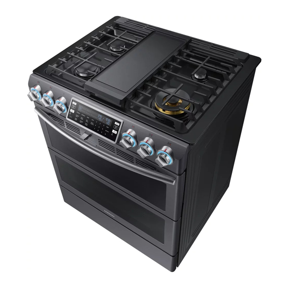
Samsung NX58K9850S Series Service Manual
Slide in gas ranges
Hide thumbs
Also See for NX58K9850S Series:
- User manual (180 pages) ,
- Installation manual (84 pages) ,
- User manual (60 pages)

Related Manuals for Samsung NX58K9850S Series


Summary of Contents for Samsung NX58K9850S Series
- Page 1 SLIDE IN GAS RANGES MODELS AND MODEL CODES: NX58K9850S * GAS RANGES CONTENTS 1. Precaution 2. Specifications 3. Disassembly and Reassembly 4. Troubleshooting 5. Wiring Diagram 6. Schematic Diagrams 7. PCB Diagrams...
-
Page 2: Table Of Contents
• Contents 1. Precaution ....................4 1-1 Forward . - Page 3 • Contents 4. Troubleshooting ..................69 4-1 Failure Display Codes .
-
Page 4: Precaution
1. Precaution 1-1 Forward This SAMSUNG Service Manual, “Slide In Gas Ranges,” provides the technician with information on the operation and service of the slide in self-cleaning gas ranges. It is to be used as a training service manual. For specific information on the model being serviced, refer to the user manual or tech sheet provided with the gas range . -
Page 5: Important Safety Instructions
This document can not be used without Samsung’s authorization. 1. Precautions 1-3 Important Safety Instructions Read and follow all instructions before using or servicing the range to prevent death, personal injury, fire, explosion, and/or property damage . This guide does not cover every possible condition that may occur . For further assistance, contact a licensed technician or the manufacturer . - Page 6 This document can not be used without Samsung’s authorization. 1. Precautions SURFACE BURNERS • Use Proper Pan Size – This appliance is equipped with CAUTION one or more surface burners of different sizes . Select utensils having flat bottoms large enough to cover...
-
Page 7: Model And Serial Number Label And Tech Sheet Locations
This document can not be used without Samsung’s authorization. 1. Precautions SELF-CLEAN OVENS • Important Instruction – In the event the self-clean mode “F” code goes on or three long beeps sound, the oven is malfunctioning in the self-clean mode . -
Page 8: Specifications
ADJUSTABLE LEVELING LEGS (4) Bake oven burner (not shown) ANTI-TIP BRACKET KIT (1) Convection Fan (2) Upper convection heater (not shown) If you need an accessory marked with a *, you can buy it from the Samsung contact center. (1-800-726-7864). -
Page 9: Control Panel - Oven
This document can not be used without Samsung’s authorization. 2. Specifications 2-2 Control Panel - Oven 1. START/SET: Start a funcition or set the time . 2. UPPER: Select the upper cooking cavity 3. OFF/CLEAR: Cancel the current operation but not the timer . -
Page 10: Control Panel - Gas Cooktop
This document can not be used without Samsung’s authorization. 2. Specifications 2-3 Control Panel - Gas Cooktop LIGHTING A GAS SURFACE BURNER Make sure all surface burners are positioned and assembled properly . 1 . Push in and turn the control knob to the LITE position . You will hear a “clicking” sound indicating the electronic ignition system is working properly . -
Page 11: Table Of Specifications
This document can not be used without Samsung’s authorization. 2. Specifications 2-4 Table of Specifications Slide In Slide in Flex Items NX58K9850S* NX58H9500W* Single Mode Twin Mode Colour Stainless Steel Stainless Steel Controls Control Type - Oven Glass Touch Glass Touch... - Page 12 This document can not be used without Samsung’s authorization. 2. Specifications Table of Specifications Slide-in Flex Slide-in Items NX58H9500W* NX58K9850S* Cooktop Cooktop Type Stainless steel Stainless steel Number of Burners Total Power (BTU) 58000 61,000 Right Front (BTU) 19,000 (Dual)
- Page 13 This document can not be used without Samsung’s authorization. 2. Specifications Table of Specifications Slide-in Flex Slide-in Items NX58H9500W* NX58K9850S* Removable Oven Door Drawer Drawer capacity (cu .ft) 0 .7 0 .7 Type Warmer Storage Drawer Heater Performance 600W Warm . Drawer Temp . Settings Low-Mid-High Warm .
-
Page 14: Accessories
This document can not be used without Samsung’s authorization. 2. Specifications 2-5 Accessories Item Description Code No. Quantity Assy-Grate Side Coating DG94-00937A Assy-Grate Center Coating DG94-00938A Plate Griddle DG61-00859A Rack-Flat DG75-01001C Assy Grate DG94-00939A Assy-Split Rack DG94-00634A Sensor Probe DG32-00013A... -
Page 15: Disassembly And Reassembly
This document can not be used without Samsung’s authorization. 3. Disassembly and Reassembly ■ Tool for assembly and disassembly Item How to use Pictures Screw driver Use for assembly and disassembly of all screws Use for assembly and disassembly of tubing to the... -
Page 16: Cover Motor Convection
This document can not be used without Samsung’s authorization. 3. Disassembly and Reassembly 3-1 COVER MOTOR CONVECTION WARNING Disconnect power before servicing the range. Replace all panels before operating range. Failure to do so can result in death or electrical shock. -
Page 17: Assy Control Box
This document can not be used without Samsung’s authorization. 3. Disassembly and Reassembly 3-2 ASSY CONTROL BOX WARNING Disconnect power before servicing the range. Replace all panels before operating range. Failure to do so can result in death or electrical shock. -
Page 18: Assy Frame Cooktop
This document can not be used without Samsung’s authorization. 3. Disassembly and Reassembly 3-3 ASSY FRAME COOKTOP WARNING Disconnect power before servicing the range. Replace all panels before operating range. Failure to do so can result in death or electrical shock. -
Page 19: Side Panel
This document can not be used without Samsung’s authorization. 3. Disassembly and Reassembly 3-4 SIDE PANEL WARNING Disconnect power before servicing the range . Replace all panels before operating range . Failure to do so can result in death or electrical shock . -
Page 20: Assy Burner Box
This document can not be used without Samsung’s authorization. 3. Disassembly and Reassembly 3-5 ASSY BURNER BOX WARNING Disconnect power before servicing the range . Replace all panels before operating range . Failure to do so can result in death or electrical shock . - Page 21 This document can not be used without Samsung’s authorization. 3. Disassembly and Reassembly Explanation Photo Guide Cooktop Rear Assy Tube Manifold Ground screw Pictures of removing Assy Burner Box...
-
Page 22: Pcb Assembly
This document can not be used without Samsung’s authorization. 3. Disassembly and Reassembly 3-6 PCB ASSEMBLY WARNING Disconnect power before servicing the range . Replace all panels before operating range . Failure to do so can result in death or electrical shock . -
Page 23: Wifi Pcb
This document can not be used without Samsung’s authorization. 3. Disassembly and Reassembly 3-7 WIFI PCB WARNING Disconnect power before servicing the range . Replace all panels before operating range . Failure to do so can result in death or electrical shock . - Page 24 This document can not be used without Samsung’s authorization. 3. Disassembly and Reassembly WIFI PCB Parts Explanation Explanation Photo WiFi holder PCB Hook of cover PCB Hook of Holder PCB Open the drawer and remove 1 screw from WiFi holder PCB...
-
Page 25: Spark Module, Knob Led
This document can not be used without Samsung’s authorization. 3. Disassembly and Reassembly 3-8 SPARK MODULE, KNOB LED WARNING Disconnect power before servicing the range . Replace all panels before operating range . Failure to do so can result in death or electrical shock . -
Page 26: Assy Display, Rotary Switch
This document can not be used without Samsung’s authorization. 3. Disassembly and Reassembly 3-9 ASSY DISPLAY, ROTARY SWITCH WARNING Disconnect power before servicing the range . Replace all panels before operating range . Failure to do so can result in death or electrical shock . - Page 27 This document can not be used without Samsung’s authorization. 3. Disassembly and Reassembly 3-9 ASSY DISPLAY, ROTARY SWITCH WARNING Disconnect power before servicing the range . Replace all panels before operating range . Failure to do so can result in death or electrical shock .
-
Page 28: Electrode
This document can not be used without Samsung’s authorization. 3. Disassembly and Reassembly 3-10 ELECTRODE Parts Explanation Explanation Photo Gas Orifice Burner Cup Tube Follow the steps on 3-1 and 3-3 . Disconnect the wire connectors from the terminal on the Spark module . - Page 29 This document can not be used without Samsung’s authorization. 3. Disassembly and Reassembly 3-10 ELECTRODE WARNING Disconnect power before servicing the range. Replace all panels before operating range. Failure to do so can result in death or electrical shock. WARNING EXPLOSION, FIRE, AND ASPHYXIATION HAZARD Shut off gas supply to the range before servicing.
-
Page 30: Burner Cup
This document can not be used without Samsung’s authorization. 3. Disassembly and Reassembly 3-11 BURNER CUP Parts Explanation Explanation Photo Tube Burner Cup Follow the steps on 3-1 and 3-3 . Using a tubing wrench on the gas line fitting and a channel... - Page 31 This document can not be used without Samsung’s authorization. 3. Disassembly and Reassembly 3-11 BURNER CUP WARNING Disconnect power before servicing the range . Replace all panels before operating range . Failure to do so can result in death or electrical shock .
-
Page 32: Gas Orifice Nozzle
This document can not be used without Samsung’s authorization. 3. Disassembly and Reassembly 3-12 GAS ORIFICE NOZZLE Parts Explanation Explanation Photo To remove the gas orifice, place the burner cup in a vise and remove the orifice with a 9/32- inch socket wrench . -
Page 33: Valve Cooktop
This document can not be used without Samsung’s authorization. 3. Disassembly and Reassembly 3-13 VALVE COOKTOP WARNING Disconnect power before servicing the range. Replace all panels before operating range. Failure to do so can result in death or electrical shock. - Page 34 This document can not be used without Samsung’s authorization. 3. Disassembly and Reassembly 3-13 VALVE COOKTOP Parts Explanation Explanation Photo Switch Ignition Follow the steps 3-2 and 3-3 . Open or remove a Door . Place a finger behind each side...
- Page 35 This document can not be used without Samsung’s authorization. 3. Disassembly and Reassembly 3-13 VALVE COOKTOP WARNING Disconnect power before servicing the range . Replace all panels before operating range . Failure to do so can result in death or electrical shock .
-
Page 36: Switch Ignition
This document can not be used without Samsung’s authorization. 3. Disassembly and Reassembly 3-14 SWITCH IGNITION Parts Explanation Explanation Photo Switch Ignition Follow the step 3-1,3-2 and 3-3 . Place a finger behind each side of the switch ignition and pull it straight out to release it from the control shaft . - Page 37 This document can not be used without Samsung’s authorization. 3. Disassembly and Reassembly 3-14 SWITCH IGNITION WARNING Disconnect power before servicing the range . Replace all panels before operating range . Failure to do so can result in death or electrical shock .
-
Page 38: Assy Motor , Tco
This document can not be used without Samsung’s authorization. 3. Disassembly and Reassembly 3-15 ASSY MOTOR , TCO Parts Explanation Explanation Photo Hooks of Bracket Motor Rear Follow the steps on 3-1 and 3-3 . Remove 2 screws from the Guide Cooktop Rear and a Bracket Motor Front . - Page 39 This document can not be used without Samsung’s authorization. 3. Disassembly and Reassembly 3-15 ASSY MOTOR , TCO WARNING Disconnect power before servicing the range . Replace all panels before operating range . Failure to do so can result in death or electrical shock .
-
Page 40: Assy Door Latch
This document can not be used without Samsung’s authorization. 3. Disassembly and Reassembly 3-16 ASSY DOOR LATCH Parts Explanation Explanation Photo Cavity Front Bracket-Latch Rear Follow steps on 3-5 . Remove 2 screws from the Cavity Front . Remove 1 screws from the... - Page 41 This document can not be used without Samsung’s authorization. 3. Disassembly and Reassembly 3-16 ASSY DOOR LATCH WARNING Disconnect power before servicing the range . Replace all panels before operating range . Failure to do so can result in death or electrical shock .
-
Page 42: Assy Probe
This document can not be used without Samsung’s authorization. 3. Disassembly and Reassembly 3-17 ASSY PROBE Parts Explanation Explanation Photo Connector of Assy Probe Assy Probe Follow steps on 3-4 . (removal of the left side panel) . To replace the Assy Probe,... -
Page 43: Switch-Door Plunger
This document can not be used without Samsung’s authorization. 3. Disassembly and Reassembly 3-18 SWITCH-DOOR PLUNGER WARNING Disconnect power before servicing the range . Replace all panels before operating range . Failure to do so can result in death or electrical shock . -
Page 44: Assy Lamp
This document can not be used without Samsung’s authorization. 3. Disassembly and Reassembly 3-19 ASSY LAMP WARNING Disconnect power before servicing the range . Replace all panels before operating range . Failure to do so can result in death or electrical shock . -
Page 45: Sensor-Thermister
This document can not be used without Samsung’s authorization. 3. Disassembly and Reassembly 3-20 SENSOR-THERMISTER WARNING Disconnect power before servicing the range . Replace all panels before operating range . Failure to do so can result in death or electrical shock . -
Page 46: Gasket-Door
This document can not be used without Samsung’s authorization. 3. Disassembly and Reassembly 3-21 GASKET-DOOR Parts Explanation Explanation Photo 1 . Open the oven door to its fully down position . 2 . Pull the ends of the gasket out of the liner holes . -
Page 47: Oven Door (Upper)
This document can not be used without Samsung’s authorization. 3. Disassembly and Reassembly 3-22 OVEN DOOR (UPPER) WARNING Disconnect power before servicing the range. Replace all panels before operating range. Failure to do so can result in death or electrical shock. - Page 48 This document can not be used without Samsung’s authorization. 3. Disassembly and Reassembly OVEN DOOR (UPPER) Parts Explanation Explanation Photo To replace door 1 . Firmly grasp both sides of the door at the top position . 2 . Fully open the door . (If the door...
-
Page 49: Handle-Door, Glass-Inner (Upper)
This document can not be used without Samsung’s authorization. 3. Disassembly and Reassembly 3-23 HANDLE-DOOR, GLASS-INNER (UPPER) Parts Explanation Explanation Photo Remove the oven door from the range Place the oven door on a padded work surface with the front glass facing down . - Page 50 This document can not be used without Samsung’s authorization. 3. Disassembly and Reassembly HANDLE-DOOR, GLASS-INNER (UPPER) Parts Explanation Explanation Photo To remove Handle-Door Remove 2 screws to remove Handle- Door HANDLE- DOOR , GLASS-INNER To remove Glass-Inner Remove 4 screws to remove the Glass inner sub .
-
Page 51: Glass-Inner (Upper)
This document can not be used without Samsung’s authorization. 3. Disassembly and Reassembly 3-24 GLASS-INNER (UPPER) WARNING Disconnect power before servicing the range. Replace all panels before operating range. Failure to do so can result in death or electrical shock. -
Page 52: Oven Door (Whole)
This document can not be used without Samsung’s authorization. 3. Disassembly and Reassembly 3-25 OVEN DOOR (WHOLE) WARNING Disconnect power before servicing the range. Replace all panels before operating range. Failure to do so can result in death or electrical shock. - Page 53 This document can not be used without Samsung’s authorization. 3. Disassembly and Reassembly OVEN DOOR (WHOLE) Parts Explanation Explanation Photo To replace door Firmly grasp both sides of the door at the top position . Fully open the door .
-
Page 54: Glass-Inner (Whole Door)
This document can not be used without Samsung’s authorization. 3. Disassembly and Reassembly 3-26 GLASS-INNER (WHOLE DOOR) WARNING Disconnect power before servicing the range. Replace all panels before operating range. Failure to do so can result in death or electrical shock. - Page 55 This document can not be used without Samsung’s authorization. 3. Disassembly and Reassembly GLASS-INNER (WHOLE DOOR) Parts Explanation Explanation Photo Glass-Inner assembly Take out the Glass-Inner assembly . GLASS- Unfold 2 flanges of Cover- INNER Frame Inner Glass to taking...
-
Page 56: Assy Power Cord
This document can not be used without Samsung’s authorization. 3. Disassembly and Reassembly 3-27 ASSY POWER CORD WARNING Disconnect power before servicing the range. Replace all panels before operating range. Failure to do so can result in death or electrical shock. -
Page 57: Burner Broil
This document can not be used without Samsung’s authorization. 3. Disassembly and Reassembly 3-28 BURNER BROIL WARNING Disconnect power before servicing the range. Replace all panels before operating range. Failure to do so can result in death or electrical shock. - Page 58 This document can not be used without Samsung’s authorization. 3. Disassembly and Reassembly BURNER BROIL Parts Explanation Explanation Photo BRACKET HSI-WIRE Remove 1 screw of bracket HSI- wire and separate the bracket HIS-wire . Remove 4 screws of bracket- broil spreader to top of oven .
-
Page 59: Air Supply Fan
This document can not be used without Samsung’s authorization. 3. Disassembly and Reassembly 3-29 AIR SUPPLY FAN WARNING Disconnect power before servicing the range. Replace all panels before operating range. Failure to do so can result in death or electrical shock. -
Page 60: Hot Surface Ignitor, Nozzle Broil Burner, Holder Broil-Burner
This document can not be used without Samsung’s authorization. 3. Disassembly and Reassembly 3-30 HOT SURFACE IGNITOR, NOZZLE BROIL BURNER, HOLDER BROIL-BURNER WARNING Disconnect power before servicing the range . Replace all panels before operating range . Failure to do so can result in death or electrical shock. -
Page 61: Burner Bake
This document can not be used without Samsung’s authorization. 3. Disassembly and Reassembly 3-31 BURNER BAKE WARNING Disconnect power before servicing the range . Replace all panels before operating range . Failure to do so can result in death or electrical shock . -
Page 62: Hot Surface Ignitor, Nozzle Bake Burner, Holder Bake-Burner
This document can not be used without Samsung’s authorization. 3. Disassembly and Reassembly 3-32 HOT SURFACE IGNITOR, NOZZLE BAKE BURNER, HOLDER BAKE-BURNER WARNING Disconnect power before servicing the range . Replace all panels before operating range . Failure to do so can result in death or electrical shock . -
Page 63: Motor Convection
This document can not be used without Samsung’s authorization. 3. Disassembly and Reassembly 3-33 MOTOR CONVECTION WARNING Disconnect power before servicing the range . Replace all panels before operating range . Failure to do so can result in death or electrical shock . - Page 64 This document can not be used without Samsung’s authorization. 3. Disassembly and Reassembly MOTOR CONVECTION Parts Explanation Explanation Photo Unbend the bracket Unbend the bracket of the back main to the rear of the range . Pull the motor convection straight out...
-
Page 65: Heater Convection
This document can not be used without Samsung’s authorization. 3. Disassembly and Reassembly 3-34 HEATER CONVECTION WARNING Disconnect power before servicing the range . Replace all panels before operating range . Failure to do so can result in death or electrical shock . -
Page 66: Assy Valve Safety
This document can not be used without Samsung’s authorization. 3. Disassembly and Reassembly 3-35 ASSY VALVE SAFETY WARNING Disconnect power before servicing the range . Replace all panels before operating range . Failure to do so can result in death or electrical shock . - Page 67 This document can not be used without Samsung’s authorization. 3. Disassembly and Reassembly ASSY VALVE SAFETY Parts Explanation Explanation Photo ASSY VALVE SAFETY Carefully identify and mark the wires going to the ASSY VALVE SAFETY . Disconnect the 4 wires .
- Page 68 This document can not be used without Samsung’s authorization. 3. Disassembly and Reassembly ASSY VALVE SAFETY WARNING Disconnect power before servicing the range. Replace all panels before operating range. Failure to do so can result in death or electrical shock.
-
Page 69: Troubleshooting
This document can not be used without Samsung’s authorization. 4. Troubleshooting 4. Troubleshooting 4-1 Failure Display Codes There are two kinds of error codes. One denotes an oven temperature sensor error and the other denotes a safety error. Possible error codes during use can be checked before service. - Page 70 This document can not be used without Samsung’s authorization. 4. Troubleshooting Failure Display Codes “C-20” Disconnect power oven sensor Measure sensor resistance . Replace the oven sensor . (1080Ω at the room temperature * reconnect Check the connecting condition of harness...
- Page 71 This document can not be used without Samsung’s authorization. 4. Troubleshooting Failure Display Codes Safety error Information code Meaning SOLUTION 1 . Disconnect power . Open the back cover . Disconnect sensor harness from the main PCB . Measure sensor resistance :1080Ω...
- Page 72 This document can not be used without Samsung’s authorization. 4. Troubleshooting Failure Display Codes Safety error ConV Relay Broil Relay “C-21” DLB Relay Bake Relay Disconnect power and Assy Display PCB * Replace Main PCB * Check the DLB, Bake and Broil relay. (Normal:∞ Ω)
- Page 73 This document can not be used without Samsung’s authorization. 4. Troubleshooting Failure Display Codes Safety error Informaion code Meaning SOLUTION 1 . Check whether cable of keypad has been inserted into connector of main PCB . 2 . Check whether between main PCB and connector or...
- Page 74 This document can not be used without Samsung’s authorization. 4. Troubleshooting Failure Display Codes Safety error Key Connector (CN201) Assy display PCB “C-d0” FPCB *Disconnect power . *Take out the assy ITO glass from the display PCB . Assy ITO glass * Repair the area of the circuit with shorted connector pins on Main PCB .
- Page 75 This document can not be used without Samsung’s authorization. 4. Troubleshooting Failure Display Codes Safety error Informaion code Meaning SOLUTION 1 . Disconnect power . Open the back cover . C heck whether harness has been connected with door lock switch and motor .
- Page 76 This document can not be used without Samsung’s authorization. 4. Troubleshooting Failure Display Codes Safety error “C-d1” *Disconnect power . *Get rid of harness connected with Lock motor . * Micom switch check (com-NO) * Replace micro switch or Lock motor .
- Page 77 This document can not be used without Samsung’s authorization. 4. Troubleshooting Failure Display Codes Safety error FAILURE CODE Meaning SOLUTION 1 . I nsert a divider in upper, lower and twin mode or remove a divider in single mode .
- Page 78 This document can not be used without Samsung’s authorization. 4. Troubleshooting Failure Display Codes Safety error “-dC-” If Single cavity cooking mode ? Please take out divider If double cavity cooking mode ? Please insert divider IPlease check divider sensing switch .
- Page 79 This document can not be used without Samsung’s authorization. 4. Troubleshooting Failure Display Codes Safety Error Information code Meaning SOLUTION 1 .Main ↔ VFD module communication 1 . Check version to program (Main:1205 Sub:1201 VFD:1205) information C-F0 2 .Main ↔ SUB 2 .
- Page 80 This document can not be used without Samsung’s authorization. 4. Troubleshooting Failure Display Codes Safety Error Information code Meaning SOLUTION Main ↔ Touch 1 . Check version to program (Main : 1205 , Touch : 03) C-F2 communication 2 . Check wire harness . (Main PCB : CN470 , SUB : CN450) information “C-F2”...
- Page 81 This document can not be used without Samsung’s authorization. 4. Troubleshooting Failure Display Codes Safety Error Information code Meaning SOLUTION 1 . Check the information code Air intake motor information . BLDC motor operating C-A2 2 . Check connect the wire harness .
- Page 82 This document can not be used without Samsung’s authorization. 4. Troubleshooting Failure Display Codes Safety Error Information code Meaning SOLUTION 1 . Used meat probe, If disconnect 3seconds . C-23 Meat probe short 2 . Check connect the wire harness...
- Page 83 This document can not be used without Samsung’s authorization. 4. Troubleshooting Error Trouble Shooting SYMPTOM DIAGNOSIS REMEDY Measure the input voltage at the Check the circuit breaker or fuse for the plug . (120VAC) range circuit . Measure the input voltage at terminal Make sure all wires are connected to the T01 on the PCB .
- Page 84 This document can not be used without Samsung’s authorization. 4. Troubleshooting Error Trouble Shooting SYMPTOM DIAGNOSIS REMEDY The oven temperature exceeds Repair or replace the faulty broil or bake 400˚F(202˚C) within 10 minutes of relay . room temperature operation .
- Page 85 This document can not be used without Samsung’s authorization. 4. Troubleshooting Error Trouble Shooting SYMPTOM DIAGNOSIS REMEDY Make sure the door lock feature is Unlock the controls by pressing and not turned on . holding the lock key for 3 or more seconds .
- Page 86 This document can not be used without Samsung’s authorization. 4. Troubleshooting Error Trouble Shooting SYMPTOM DIAGNOSIS REMEDY There is no electrical power to the Plug in the power cord and/or reset the range . circuit breaker for the range .
- Page 87 This document can not be used without Samsung’s authorization. 4. Troubleshooting Error Trouble Shooting SYMPTOM DIAGNOSIS REMEDY Soft blue flames are normal flames Cooktop burner for NG operation . flames are soft This is normal . blue or have Soft blue flames with yellow tips are yellow tips .
-
Page 88: Control Parts
This document can not be used without Samsung’s authorization. 4. Troubleshooting 4-2 Control parts No display CN700 No display Make sure that power cord is *Insert the power cord. connected. Check the voltage of the Power *Replace the Power cord. - Page 89 This document can not be used without Samsung’s authorization. 4. Troubleshooting Control parts Touch Keypad is not working properly Touch control keypads are not working properly. Make sure the Door lock feature Touch the Start/Set keypad is not turned on .
- Page 90 This document can not be used without Samsung’s authorization. 4. Troubleshooting Control parts Buzzer does not beep when keypad is touched . Buzzer does not beep when keypad is touched. *Faulty buzzer on PCB. *Replace the PCB.
-
Page 91: Cooktop Parts
This document can not be used without Samsung’s authorization. 4. Troubleshooting 4-3 Cooktop parts Cooktop burner not lighted [Gas malfunction] No cooktop burners will light. * Make sure the gas supply valve to * Fully open the gas supply valve. - Page 92 This document can not be used without Samsung’s authorization. 4. Troubleshooting Cooktop parts Cooktop burners not lighted [Electric malfunction] No cooktop Burners will light *Plug in the power cord and/or * Make sure there is power to the reset the circuit breaker for the range range.
- Page 93 This document can not be used without Samsung’s authorization. 4. Troubleshooting Cooktop parts One cooktop burner not lighted [Electric malfunction] One cooktop burner will not light. Check whether the burner head and *Assemble the burner head and cap is properly assembled.
- Page 94 This document can not be used without Samsung’s authorization. 4. Troubleshooting Cooktop / Oven parts Gas Leaked Gas Leaked * Check gas pipes on back side are * Assemble the gas pipes on the properly assembled . (4 points) right position .
- Page 95 This document can not be used without Samsung’s authorization. 4. Troubleshooting Cooktop / Oven parts The flame looks abnormal. [Yellow tip / Lift flame] Yellow tip / Lift flame 1 .78 1 .04 1 .40 0 .83 1 .38 0 .83 1 .36/1 .36/0 .85...
- Page 96 This document can not be used without Samsung’s authorization. 4. Troubleshooting Cooktop / Oven parts Flame size is too big or too small Flame size is too big or small. *Check the orifice nozzle diameter. *Replace the orifice nozzle. *Reverse the direction of the orifice.
-
Page 97: Oven Parts
This document can not be used without Samsung’s authorization. 4. Troubleshooting 4-4 Oven parts Oven burner will not light [Broil / Bake burner] Oven burner will not light. *Turn on the cooktop burners to *Open the gas valve. check whether the gas is properly supplied. - Page 98 This document can not be used without Samsung’s authorization. 4. Troubleshooting Oven parts Oven temperature rises too slowly (Electrical) Oven Temp rises to slowly. T503 T505 T504 *Turn on the cooktop burners to *Open the gas valve. check whether the gas is properly supplied.
- Page 99 This document can not be used without Samsung’s authorization. 4. Troubleshooting Oven parts Oven temperature rises too fast . [Electric malfunction] Oven Temp rises to fast . * Check to see if oven exceeds 400℉(204℃)with in 10 minutes of * Repair or replace the harness .
- Page 100 This document can not be used without Samsung’s authorization. 4. Troubleshooting Oven parts Oven temperature rises too slow or too fast [Gas malfunction] Oven temperature rises too slow or too fast . * Make sure the gas supply valve * Fully open the gas supply valve .
- Page 101 This document can not be used without Samsung’s authorization. 4. Troubleshooting Oven parts Oven lamp not working Oven lamp is not working . * While holding the oven door open, * Make sure the control lockout press and hold the lockout keypad feature is not turned on .
- Page 102 This document can not be used without Samsung’s authorization. 4. Troubleshooting Oven parts Convection fan not working Convection fan not working . Measure resistance value Replace the Motor . of Motor terminal after taking off harness from Motor . [25Ω±7%] Measure the voltage of After touch the Conv .
-
Page 103: Electrical Malfunction (Ver.00)
Troubleshooting (Wi-Fi connection) Step 1 . - Check whether display showed • If display showed icon, check to ‘Samsung Smart Home’ app . Delete and re-install the app . And then, try again (Follow manual instruction for samsung smart home app) . -
Page 104: Electrical Malfunction (Ver.01)
Troubleshooting (Wi-Fi connection) Step 1 . - Check whether display showed • If display showed icon, check to ‘Samsung Connect’ app . Delete and re-install the app . And then, try again (Follow manual instruction for Samsung Connect app) . -
Page 105: Wiring Diagram
This document can not be used without Samsung’s authorization. 5. Wiring Diagram 5. Wiring Diagram 5-1 Wiring Diagram... - Page 106 This document can not be used without Samsung’s authorization. 5. Wiring Diagram Wiring Diagram...
-
Page 107: Schematic Diagrams
This document can not be used without Samsung’s authorization. 6. Schematic Diagrams 6-1 Schematic Diagrams (This Document can not be used without Samsung’s authorization) -
Page 108: Pcb Diagrams
This document can not be used without Samsung’s authorization. 7. PCB Diagrams 7. PCB Diagrams 7-1 Figure of PCB and Display PCB MAIN BLDC PCB ASSY DISPLAY... -
Page 109: Explanation Of Touch Keypad
This document can not be used without Samsung’s authorization. 7. PCB Diagrams 7-2 Explanation of Touch Keypad NX58K9850S* Touch Keypad 1 . Touch control panel allows user to operate the oven, oven light, warming drawer and Convection heater, and clock and timer operation by touching the control panel in the front . -
Page 110: Explanation Of Nx58K9850S* Main Pcb Parts
This document can not be used without Samsung’s authorization. 7. PCB Diagrams 7-3 Explanation of NX58K9850S* Main PCB parts Parts Part Name Funtion and Rule Number This is relay which control source of DLB, Bake, Broil, Warming RY201 RY-Source Relay Drawer relay . - Page 111 This document can not be used without Samsung’s authorization. 7. PCB Diagrams Parts Part Name Funtion and Rule Number RY209 Conv-Lamp-U Relay This is relay which is connected with Conv-Lamp-Upper RY210 Door Lock Relay This is relay which is connected with door lock motor .
-
Page 112: Explanation Of Nx58K9850S* Display Pcb Parts
This document can not be used without Samsung’s authorization. 7. PCB Diagrams 7-4 Explanation of NX58K9850S* Display PCB parts Parts Part Name Funtion and Rule Number CN430 JTAG Monitoring Connector This is connected with JTAG equipment . CN620 HASS Connector This is connector for HASS (Smart Test) . -
Page 113: Explanation Of Nx58K9850S* Bldc Pcb Parts
This document can not be used without Samsung’s authorization. 7. PCB Diagrams 7-5 Explanation of NX58K9850S* BLDC PCB parts Parts Part Name Funtion and Rule Number CN100 Power Connector This is to supply power with SMPS . CN300 SLIDE_IN_VE PBA Connector This is connector which is connected with SLIDE_IN_VE PBA . - Page 114 North & Latin America gspn3.samsungcsportal.com China china.samsungportal.com This service manual is the property of Samsung Electronics Co., Ltd. © Samsung Electronics Co ., Ltd . January, 2018 Any unauthorized use of this manual can be punished under applicable Printed in Korea...