Advertisement
EN
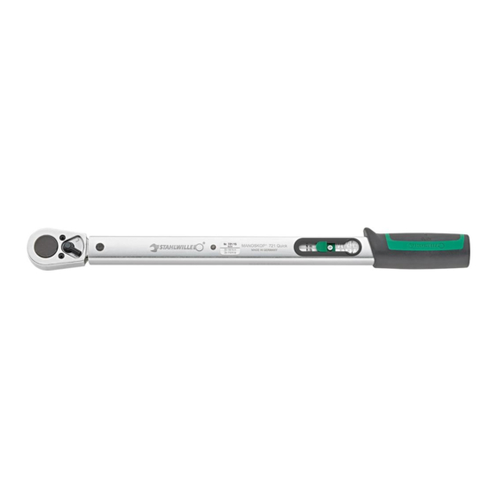
STAHLWILLE
Standard MANOSKOP
721
Service MANOSKOP
730
List of contents
Technical description ..................28
Safety instructions ......................32
Operation ....................................35
Maintenance ...............................44
Cleaning .....................................49
Accessories ................................50
Disposal ......................................50
Technical description
All models
®
MANOSKOP
721, 730 are adjustable
torque wrenches with a cut-out, tactile
and audible cut-out signals.
These torque wrenches have a safety
cut-out mechanism.
The wrench is set to cut-out at a
certain torque level by setting the
required value on the force-free sliding
scale.
The setting slide has an automatic
setting fail-safe mechanism.
The measuring element is a flexible
rod. The flexible rod is not
pretensioned so it is only under tension
from the start to the end of the actual
tightening operation until the wrench
cuts out.
28
®
®
Advertisement

Related Manuals for Stahlwille Standard MANOSKOP 721/5


Summary of Contents for Stahlwille Standard MANOSKOP 721/5
-
Page 1: Table Of Contents
STAHLWILLE ® Standard MANOSKOP ® Service MANOSKOP List of contents Technical description ....28 Safety instructions ......32 Operation ........35 Maintenance .......44 Cleaning ........49 Accessories ........50 Disposal ........50 Technical description All models ® MANOSKOP 721, 730 are adjustable torque wrenches with a cut-out, tactile and audible cut-out signals. - Page 2 As soon as the torque wrench is released, it is ready for the next job. These wrenches will only tighten in one direction. To use the wrench for loosening, turn it over. Exception: The ® MANOSKOP 721/5, 721/15 and 721/20 cannot be used for counter clockwise tightening.
- Page 3 ® Service MANOSKOP 730/2 to 730/65 ..can be fitted with various insert tools. For this purpose, the head of the wrench has a recessed square drive at the face (sizes are shown in the Technical Specifications) with a double-sided locating hole and insertion groove.
-
Page 5: Safety Instructions
Safety instructions Intended Purpose ® MANOSKOP 721 and 730 have been designed for controlled tightening of screw joints in a workshop environment. In order to loosen a nut or bolt during the normal tightening process, the ® MANOSKOP can also be used in the ®... - Page 6 ® The MANOSKOP may not be used as a hammer. This will lead to injury and damage. Structural features of the information on dangers CAUTION Notices containing the word CAUTION warn of a hazardous situation which may lead to slight or moderate injuries.
- Page 7 ATTENTION! Impermissible deviation from the triggering accuracy leads to a risk of material damage. Make sure that the triggering accuracy is checked at the prescribed intervals and is adjusted if required. Unless internal regulations at the place of use say otherwise (e.g. test equipment inspection to ISO 9000 et seq.) inspection should take place after approx.
-
Page 8: Operation
Operation ® MANOSKOP 721 and 730 are measuring instruments and must be treated with utmost care. Avoid subjecting the tool to physical knocks, chemicals or excessive temperatures beyond the limits given in these instructions. Please note that extremes of climate (cold, heat, humidity) may affect measuring accuracy. - Page 9 CAUTION Faulty or incorrect plug- in tools lead to a risk of injury. Exclusively use plug-in tools from STAHLWILLE. Make sure that the permissible load capability of the plug-in tool exceeds the capacity of the torque wrench.
- Page 10 Attaching insert tools 721/5, 721/15 and 721/20 1. For controlled clockwise tightening, switch the ratchet to „R“ or, for uncontrolled loosening of joints, to „L“. 2. Slide the insert over the square drive of the ratchet until it locates. 721/30 1.
- Page 11 4. Slide the insert over the square drive until it locates. Attaching insert tools - 730/2 to 730/65 1. Insert the insert tool into the internal square drive on the face of the head of the wrench. The spring-loaded locking pin of the insert tool will be pressed down by the insertion groove.
- Page 12 Removing insert tools 730/2 and 730/4 1. Insert a fine punch into the locating hole of the shell tool from outside. Use the punch to depress the locking pin. 2. Remove the insert tool. 730/5 to 730/65 1. If the tool was attached in the „normal“ position, press the release button on the underside of the head of the wrench.
- Page 13 Proceed as follows: 1. Depress the button on the underside of the tool, or the pressure plate in the end of the handle as appropriate, to release the setting fail-safe mechanism. 2. Slide the scale to a torque level lower than the desired cut-out value.
- Page 14 4. Release the button / pressure plate. The torque level is now set. 5. Check the value again. If the setting is wrong, return to 1. Controlled counter clockwise tightening For reasons of accuracy, these torque wrenches have been designed to work in only one direction.
- Page 15 For controlled counter clockwise ® tightening using the MANOSKOP 730/2 to 730/65, the insert tool has to be rotated through 180°. Ratchet insert tools also need switching to „L“ (CCW) for the correct tightening direction. Uncontrolled loosening of nuts & bolts ..
- Page 16 CAUTION Slipping tools lead to a risk of injury. Make sure that the tool cannot slip off the workpiece. ATTENTION! Unsecured plug-in tools lead to a risk of material damage. Make sure that plug-in tools are always secured against pulling out by engaging the retaining pin.
-
Page 17: Maintenance
ATTENTION! Incorrect use of the torque wrench leads to the risk of material damage. Make sure that the tightening process is immediately ceased after the torque wrench has triggered. As soon as the torque wrench has cut out, it is ready for the next job. Maintenance The internal mechanisms of the torque wrench are subject to normal wear and... - Page 18 If you have access to such a tester, you ® may inspect the MANOSKOP yourself. Suitable torque testers are available from STAHLWILLE. It is also possible for ® STAHLWILLE to test the MANOSKOP for you. To carry out the test, proceed as follows: 1.
- Page 19 Adjusting for deviations in cut-out value You may return your torque wrench to STAHLWILLE for adjustment. You will then receive the tool back with a new works calibration certificate. You may adjust the torque wrench yourself. In this case, however, STAHLWILLE‘s accuracy guarantee is...
- Page 20 A torque tester is necessary for the inspection with sufficient capacity for the wrench to be tested and with a guaranteed accuracy of ± 1% of the displayed reading. ® Every MANOSKOP has two adjusting screws inside for readjustment purposes. These are accessible with an Allen key, size 2 mm, through two holes in the housing.
- Page 21 Proceed as follows: ® 1. With the MANOSKOP 730/2 and 730/4, remove the plastic cover first. With other models, remove the two plugs using a sharp object. Retain the plugs for later use. 2. To adjust the lower end of the range, insert the Allen key in the hole nearer to the handle.
-
Page 22: Cleaning
Consult STAHLWILLE if this occurs. 7. Replace the plastic handle or plugs as appropriate to protect the cut-out mechanism against dirt and damp. -
Page 23: Accessories
Accessories For all models Inserts for square drives for all usual screw head types and sizes. For STAHLWILLE Service ® MANOSKOP Insert tools ratchet insert tools square insert tools open-jaw insert tools ring insert tools ...
Need help?
Do you have a question about the Standard MANOSKOP 721/5 and is the answer not in the manual?
Questions and answers