Table of Contents

Related Manuals for Shire GSHE0706DSL-1AA


Summary of Contents for Shire GSHE0706DSL-1AA
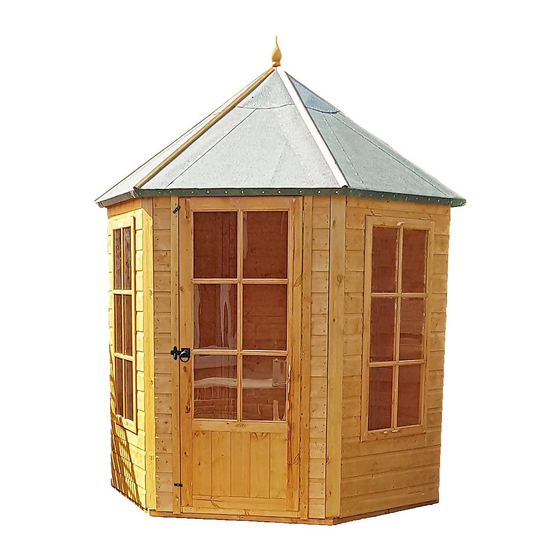
- Page 1 Batch No xxxx © Gazebo Summerhouse 2020 These instructions are for your safety. Please read through them thoroughly before use. PLEASE KEEP THIS LEAFLET FOR FUTURE REFERENCE GSHE0706DSL-1AA 5060437982039 GSHE0606PSL-1AA 5060490133447...
-
Page 2: Table Of Contents
Let’s get started... Important information... Safety Preparation of base Warranty Care, maintenance & Recycling In more detail... Parts List Fascia & Nail List Hardware chart Before you start Detailed Technical Drawing 10-11 Assembly instructions 12-28 For a copy of the instructions or a copy in another language please send an email or write to the address below. -
Page 3: Safety
Safety Check that you have noted all the following instructions: We advise the use of non slip protective gloves throughout the assembly process. We advise the use of steel capped protective footwear throughout the assembly process. We advise that you use a helper to hold the glass in position whilst you nail the beading in place. -
Page 4: Preparation Of Base
Base and Warranty Preparation of base... We recommend that the base onto which your building will stand should be at least 75mm larger in each direction than the total floor size of the building. Actual floor area of the building: 2156mm x 1867mm ... -
Page 5: Care, Maintenance & Recycling
Care, Maintenance and Recycling The 5 golden rules of care: Ensure your base is level and firm. Ensure the building is not sitting directly on the ground using damp proof membrane or the optional timber base. Ensure every piece of timber and surface, especially that is hidden upon assembly is treated with a top quality wood preservative at least twice (before assembly). -
Page 6: Parts List
Stacked Parts List Description (part No ) - Qty... -
Page 7: Fascia & Nail List
Fascia Bag Parts List Description (part No ) - Qty Nail Bag Parts List Description (part No ) - Qty... -
Page 8: Hardware Chart
Description Nail bag contents (part No ) - Qty Hardware Chart Scale 1:1 8mmFelt Nail (A0266) x350 16mm Panel Pin (A0024) x144 40mmRound head nail (A0025) x24 25mm Posi-drive screw (A0032) x41 Black 25mm Posi-drive screw (A0031 ) x10 50mm Posi-drive screw (A0557) x18 60mmPosi-drive screw (A0035) x46... -
Page 9: Before You Start
Before you start... Things to check before you start: Ensure your base is ready – See page 4 Check all parts as listed in the parts lists Read the instructions fully before starting work Follow all the health and safety guidelines. When you see the drill icon Only ever drill through the first piece of framework which will be a... -
Page 12: Assembly Instructions
Assembly These instructions are for your safety. Please read through them thoroughly before use . the parts before assembly –see page 5 Treat all The hinges fit the top of the window. Try the window in position to check that you have it the correct way GB-IE around. - Page 13 GB-IE Position 3 hinges on the door and fix at the 2 inner holes. Door (B0055p)x01 Hinges (A0013) x03 25mmScrews (A0032)x06 Lay the door B0055p face down and carefully place the door panel A4071 over the top of it, outer face GB-IE down.
- Page 14 Position the Gate latch “A0015" on the outside over the door”A0012” framework. Mark the screw holes as shown. Drill the middle hole only and fit the "SQUARE SHAFT" in the hole, GB-IE locate the two ring handles onto the shaft and fix to the door. Align and pre drill the catch plate with the latch block and fit to the adjacent panel.
- Page 15 Drill 3 holes through each side of the Plain panels A5633 framework and two for the floor. The bottom of the panels have an overhang which fits flush to the floor. GB-IE The widest part of the post must be on the outside. The widest part must be flush with the outside cladding.
- Page 16 Position and fix two posts as before. GB-IE Corner Post (A4069)x02 60mmScrew A0035 GB-IE Position and fix the last plain panel to the RH post. Fix another post to the plain panel that you just fitted. Plain Panel A5633 Corner Post (A4069)x01 60mmScrew A0035...
- Page 17 Pre drill both of the window panel assemblies GB-IE Drill three holes in each side at an angle so you can get the screw in and two at the bottom. 5 mm Window panel Step 2 x 02 GB-IE Using the holes drilled previously fix the window panel to the LH post. Fix another post to the window panel as before.
- Page 18 Repeat with the other window panel. GB-IE Window panel Step 10 x 01 Corner Post (A4069)x01 60mmScrew A0035 Pre drill f the door panel assembly. GB-IE Drill three holes in each side at an angle so you can get the screw in and two at the bottom. 5 mm Door Panel Step 05 x 01...
- Page 19 Position and fix the door panel to the posts. GB-IE Door Panel Step13x 01 60mmScrew A0035 Roll out felt on a clean, flat surface (Back side up). Place one of the six triangular roof panel sections onto GB-IE this as in the picture (framework upwards). You must allow for a 50mm overhang of felt along the bottom edge (the shortest side 1183mm) of the panel.
- Page 20 Fix the felt overhang to the bottom edge of the roof panel using 11 x felt nails (as below drawing). GB-IE Turn the roof panel over and fix the felt to the long edges using 6 x felt nails per edge. Roof Panel (A4080)x 01 8.0m Felt Roll...
- Page 21 This image shows full cutting layout of the felt. GB-IE 8.0m Felt Roll (A4081)x01 GB-IE Using a piece of straight wood as a marking and cutting guide . Mark out and cut 6 strips. 8.0m Felt Roll (A4081)x01...
- Page 22 Drill 3 holes through the framework on one (the same) long side of all the roof panels. GB-IE 5 mm Roof Panel (A4080)x 06 Note: Two people are required for the roof assembly stages. GB-IE Take two roof panels with the bottom edges resting on the ground and join together using 3 x 50mm screws.
- Page 23 Add the next roof panel and fix through the holes drilled in step 20. GB-IE Roof Panel (A4080)x 01 50mmScrew (A0557)x03 GB-IE Add the next roof panel and fix through the holes drilled in step 20. Roof Panel (A4080)x 01 50mmScrew (A0557)x03...
- Page 24 Add the next roof panel and fix through the holes drilled in step 20. GB-IE Roof Panel (A4080)x 01 50mmScrew (A0557)x03 GB-IE The last panel you will need to tip the assembly up and position and fix to the adjoining panels. Roof Panel (A4080)x 01 50mmScrew...
- Page 25 At least two people should lift the roof assembly into position. GB-IE The framework should sit in the middle of each post. Ensure everything is square and true. Drill a hole at an angle through the top of the post only and secure with an 80mm screw. GB-IE Repeat at all the posts.
- Page 26 Fix the 1450mm x 333mm strips over the joins of the triangular roof pieces using 13 felt nails down each side. The top of the strip can be folded onto adjacent roof panels. GB-IE The end of the strip that overhangs the roof needs to be folded under the overhang and secured there using 3 x felt nails.
- Page 27 Take the finial and screw the double ended screw directly in the centre of it. Fix the finial to the top of the roof by screwing the exposed half of the double ended screw into the point GB-IE where the roof panels meet. Finial (A0111)x01 Double end screw...
- Page 28 GLASS HANDLE WITH CARE DANGER OF CUTTING GB-IE USE GLOVES ,SUITABLE SHOES AND CLOTHIN Swap the beading around to get the best fit. Fit with 2 panel pins each Get a helper to hold the glazing in position while you fit the beading 8.5mm Beading (A0021) x36...
Need help?
Do you have a question about the GSHE0706DSL-1AA and is the answer not in the manual?
Questions and answers