
Related Manuals for Shire Arbour Foxglove


Summary of Contents for Shire Arbour Foxglove
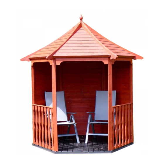
- Page 1 Batch No.4427 © Shire Arbour Foxglove These instructions are for your safety. Please read through them thoroughly before use. PLEASE KEEP THIS LEAFLET FOR FUTURE REFERENCE...
-
Page 2: Table Of Contents
Let’s get started... Important information... Safety Preparation of base Warranty Care, maintenance & Recycling In more detail... Parts List Hardware chart Detailed Technical Drawing 08-09 Before you start Assembly instructions 11-20 For a copy of the instructions or a copy in another language please send an email or write to the address below. -
Page 3: Safety
Safety Check that you have noted all the following instructions: We advise the use of non slip protective gloves throughout the assembly process. We advise the use of steel capped protective footwear throughout the assembly process. We advise that you use a helper to hold the glass in position whilst you nail the beading in place. -
Page 4: Preparation Of Base
Base and Warranty Preparation of base... We recommend that the base onto which your building will stand should be at least 75mm larger in each direction than the total floor size of the building. Actual floor area of the building: 2156mm x 1867mm ... -
Page 5: Care, Maintenance & Recycling
Care, Maintenance and Recycling The 5 golden rules of care: Ensure your base is level and firm. Ensure the building is not sitting directly on the ground using damp proof membrane or the optional timber base. Ensure every piece of timber and surface, especially that is hidden upon assembly is treated with a top quality wood preservative at least twice (before assembly). -
Page 6: Parts List
Stacked Parts List Description (part No ) - Qty... -
Page 7: Hardware Chart
Nail bag contents Description -- (part No ) - Qty: Hardware Chart Scale 1:1 40mmRound head nail (A0025) x06 50mm Posi-drive screw (A0557) x 48 60mmPosi-drive screw (A0035) x69 80mm Posi-drive screw (A0036) x06... -
Page 10: Before You Start
Before you start... Things to check before you start: Ensure your base is ready – See page 4 Check all parts as listed in the parts lists Read the instructions fully before starting work Follow all the health and safety guidelines. When you see the drill icon Only ever drill through the first piece of framework which will be a... -
Page 11: Assembly Instructions
Assembly instructions: These instructions are for your safety. Please read through them thoroughly before use. Treat all the parts before assembly – see page 5! GB-IE Drill 4 5mm holes through the frame work of one floor half , push the halves together and screw into place making sure both halves are inline and true. - Page 12 Slot a roof support into the Hex centre slot so they are flush at the bottom. Fix using the holes from step GB-IE Repeat with another 2 roof supports using alternate slots as below. Put to one side until later. Step 2 Roof support (A3966)x03...
- Page 13 GB-IE Drill and fix two Blocks A0091 to each Trim A3965 so they are flush with the top (longest straight side and the ends. 5 mm Trim (A3965)x03 34mm Block (A0091)x06 50mmScrew (A0557)x012 Drill 3 holes through each side of the Plain panels A3959 framework and two for the floor. The bottom GB-IE of the panels have an overhang which fits flush to the floor.
- Page 14 Fix a further 2 posts using the holes drilled previously GB-IE Make sure the panels are tight to the floor and central to each side. 5 mm Corner Post (A3960)x02 60mmScrew A0035 Fix the final plain panel and post in the same way as before. GB-IE 5 mm Plain Panel...
- Page 15 Drill 2 holes in each side and the bottom of the rail framework. GB-IE Align the rail framework with the edge of the floor and make sure the plain panels are central and against the floor before fixing to the posts. The rail slats must stick past the posts by 7mm (slats thicker than the cladding).
- Page 16 GB-IE The rail slats must stick past the posts by 7mm (slats thicker than the cladding). Fix The remaining posts to the rails. Using holes drilled previously. Corner Post (A3960)x02 60mmScrew A0035...
- Page 17 Drill and 2 holes, the top one being 20mm from the top through the ends of the blocks fitted to all the GB-IE trims. Align the top of the trims with the top of the plain panels and so the trim sticks out from the post by 7mm. Making sure all is square and true fix to the posts.
- Page 18 Position the step 3 assembly on top of the posts so they are in the middle of each post and the front of GB-IE the notch is tight to the post. Drill an angled hole through the post and fix with 5 mm Step 3 60mmScrew...
- Page 19 GB-IE Place one of the roof supports A3966 into the remaining hex slots and onto the corner post. Ensure it is flush with the bottom of the hex centre and in the middle of the post . Drill and fix to the hex centre and post with 2x 60mm screws, 5 mm Step 3 Roof support...
- Page 20 Place all roof sections in position between each roof timber. Push firmly into place. GB-IE Secure in position from the inside using 3 x 50mm screws in each roof framework - 6 in each roof panel 5 mm Roof Panel (A3968)x06 50mmScrew (A0557)x36...
Need help?
Do you have a question about the Arbour Foxglove and is the answer not in the manual?
Questions and answers