Table of Contents
Advertisement
Quick Links
INSTALLATION & OPERATION
A53685 AIRLINK MARS
SOFTWARE DEFINED RADIO (SDR)
OCTOBER 2021
DOCUMENT NO. COM-00-21-05
VERSION A
Siemens Mobility, Inc.
One Penn Plaza
Suite 1100
New York, NY 10119-1101
1-800-793-SAFE
www.usa.siemens.com/rail-manuals
Copyright © 2021 Siemens Mobility, Inc.
All Rights Reserved
PRINTED IN U.S.A.
Advertisement
Table of Contents

Related Manuals for Siemens A53685


Summary of Contents for Siemens A53685
- Page 1 A53685 AIRLINK MARS SOFTWARE DEFINED RADIO (SDR) OCTOBER 2021 DOCUMENT NO. COM-00-21-05 VERSION A Siemens Mobility, Inc. One Penn Plaza Suite 1100 New York, NY 10119-1101 1-800-793-SAFE www.usa.siemens.com/rail-manuals Copyright © 2021 Siemens Mobility, Inc. All Rights Reserved PRINTED IN U.S.A.
-
Page 2: Proprietary Information
English. Any translation of the manuals and product information is unofficial and can be imprecise and inaccurate in whole or in part. Siemens Mobility, Inc. does not warrant the accuracy, reliability, or timeliness of any information contained in any translation of... -
Page 3: Fcc Rules Compliance
Connect the equipment into an outlet on a circuit different from that to which the receiver is connected. • Consult Siemens Customer Service for help. Modifications not expressly approved by the manufacturer could void the user's authority to operate the equipment under FCC rules. -
Page 4: Human Exposure Statement
HUMAN EXPOSURE STATEMENT This equipment is designed to generate and radiate radio frequency (RF) energy using an external antenna. When terminated into a non-radiating RF load, the radio is certified to comply with FCC regulations pertaining to human exposure to RF radiation in accordance with the FCC Rules Part 1 section 1.1310 as published in title 47 code of federal regulations and procedures established in TIA/EIA TSB92, Report On EME Evaluation for RF Cabinet Emissions Under FCC MPE Guidelines. -
Page 5: General Safety Precautions
GENERAL SAFETY PRECAUTIONS Safety precautions must be observed at all times during all phases of installation, operation, service, and repair of the equipment described in this manual. The following precautions are warnings to be aware of. These warnings and precautions are necessary for the safe operation of the equipment. -
Page 6: Document History
DOCUMENT HISTORY Release Sections Version Details of Change Date Changed 10/28/21 Initial Release COM-00-21-05 OCTOBER 2021 Version No.: A... -
Page 7: Table Of Contents
TABLE OF CONTENTS Section Title Page PROPRIETARY INFORMATION ......................ii TRANSLATIONS ............................. ii WARRANTY INFORMATION ........................ii SALES AND SERVICE LOCATIONS ....................... ii FCC RULES COMPLIANCE ........................iii HUMAN EXPOSURE STATEMENT......................iv GENERAL SAFETY PRECAUTIONS ...................... v MANUAL SCOPE ............................ v DOCUMENT HISTORY .......................... - Page 8 Detection and Monitoring ...................... 2-10 INSTALLATION ..........................3-1 Installation Overview....................... 3-1 Environmental Considerations ....................3-2 3.2.1 Equipment Ventilation ....................3-2 Site Grounding ........................3-2 Input Power Requirements ..................... 3-2 Equipment Installation ......................3-3 3.5.1 Equipment Unpacking and Inspection ..............3-3 3.5.2 Equipment Mounting....................
- Page 9 5.7.3 WinSCP Actions ...................... 5-8 Base Station Configuration Files ..................... 5-9 Maintaining Multiple Configuration File Versions ..............5-10 5.10 Coordinated Configuration File Changes ............... 5-11 OPERATION ..........................6-1 Description ..........................6-1 Base Station Operation ......................6-1 6.2.1 Base Station CLI ..................... 6-1 6.2.1.1 Basic CLI Use ......................
- Page 10 LIST OF FIGURES Section Title Page Figure 1-1 A53685 Airlink Mars Radio ....................1-1 Figure 2-1 A53685 Airlink Mars System ....................2-1 Figure 2-2 Airlink Mars Radio Dimensions................... 2-3 Figure 2-3 Airlink Mars Radio Block Diagram ..................2-4 Figure 2-4 RF and IF SAW Filters ....................... 2-8 Figure 3-1 Physical Dimensions ......................
- Page 11 LIST OF TABLES Section Title Page Table 2-1 Airlink Mars Radio Subsystems ................... 2-4 Table 3-1 Connection Summary ......................3-9 Table 4-1 Troubleshooting Matrix ......................4-1 Table 5-1 Console Configuration ......................5-3 Table 5-2 Base Station Configuration Overview .................. 5-9 Table 6-1 Measurement Results Interpretation ..................
-
Page 12: Notes, Cautions, And Warnings
EQUIPMENT. CAUTIONS TAKE PRECEDENCE OVER NOTES AND ALL OTHER INFORMATION, EXCEPT WARNINGS. NOTE Generally used to highlight certain information relating to the topic under discussion. If there are any questions, contact Siemens Industry, Inc. Application Engineering. COM-00-21-05 OCTOBER 2021 Version No.: A... -
Page 13: Electrostatic Discharge (Esd) Precautions
(ESD) during the handling, shipping, and storage of electronic modules and components. Siemens Industry, Inc. has instituted these practices at its manufacturing facility and encourages its customers to adopt them as well to lessen the likelihood of equipment damage in the field due to ESD. -
Page 14: Glossary
GLOSSARY TERM DESCRIPTION Association of American Railroads - An organization that establishes uniformity and standardization among different railroad systems. Advanced Encryption Standard Branch is Less or Equal Base Station Communications Base Board Command Line Interface decibel milliwatts A DIN rail is a metal rail of a standard type widely used for mounting circuit breakers and industrial control equipment inside equipment racks. - Page 15 TERM DESCRIPTION Intermediate Frequency Internet Protocol - ISO Model Layer 3 (network) protocol that performs proper routing of packets. Intermediate & Radio Frequency Module Local Area Network - A limited network where the data transfer medium is generally wires or cable. Light Emitting Diode NEMA National Electrical Manufacturers Association...
- Page 16 TERM DESCRIPTION Surface Acoustic Wave SCADA Supervisory Control and Data Acquisition Software Defined Radio Sub-Miniature version A SNMP Simple Network Management Protocol Secure Shell Software Time Division Duplexing Transmit ULSF Up Link Sub Frame COM-00-21-05 OCTOBER 2021 Version No.: A...
-
Page 17: Product Description
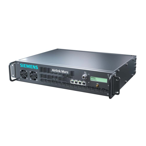
PRODUCT DESCRIPTION PRODUCT DESCRIPTION The Siemens versatile, high-performance A53685 Airlink Mars Radio Hardware Platform is capable of operating all Airlink Software Applications including the IEEE 802.16s and 802.16e air interface protocols and operation as a Base Station, Fixed Remote or Mobile Remote Radio. -
Page 18: Specifications
PRODUCT DESCRIPTION _________________________________________________________________________________________________________ Specifications RADIO SPECIFICATIONS Frequency Range 70 MHz to 6 GHz Channel Sizes 12.5 kHz to 30 MHz Throughput Up to 10 Mbps TX Power 100 Watts (50 dBm) @ Antenna Port RX Sensitivity As low as -117 dBm Waveform OFDMA Modulation... - Page 19 PRODUCT DESCRIPTION _________________________________________________________________________________________________________ Specifications (continued) PHYSICAL CHARACTERISTICS 50Ω RF Antenna (2X) Active 5 VDC Input Voltage 48 VDC +/- 25% (36 VDC – 60 VDC) Data Interface 100 Base T, RS-232 Power Consumption 350 Watts Indicators LCD Panel, Power LED 19”...
-
Page 20: Ordering Information
FCC certification of the radios in these bands is pending. Customers must have an FCC Special Temporary Authority (STA) license for the frequency band to deploy the A53685 Airlink Mars Radio. Siemens Mobility, Inc. will perform follow-up releases as radio bands achieve FCC certification. COM-00-21-05 OCTOBER 2021 Version No.: A... -
Page 21: Introduction
(BS) with BS5000 software. The Airlink radio network can be made up of Mars radios or used in conjunction with Siemens other hardware platforms to build a multi-cell, point-to-multipoint (PtMP) networks using IEEE 802.16 –... -
Page 22: Summary Of Operating Features
IEEE 802.16 – 2017 uses channel sizes from 100 kHz to 10 MHz. A revision to the standard known as IEEE 802.16t is in development to address smaller channel sizes down to 12.5 kHz. However, at this time Siemens uses a modification of the IEEE 802.16 – 2017 for channel sizes less than 100 kHz. -
Page 23: Mechanical Design
INTRODUCTION _________________________________________________________________________________________________________ Mechanical Design The Mars radio is housed in a 19” rack mount enclosure. It is not an outdoor enclosure. If an outdoor installation is needed, it needs to be installed in a NEMA 4/4X enclosure. Figure 2-2 Airlink Mars Radio Dimensions COM-00-21-05 OCTOBER 2021 Version No.: A... -
Page 24: Electrical Design
INTRODUCTION _________________________________________________________________________________________________________ Electrical Design The Mars radio is designed as shown in Figure 2-3. Figure 2-3 Airlink Mars Radio Block Diagram Table 2-1 Airlink Mars Radio Subsystems Subsystem Description Manufacturer Power Supply Unit Ondas Networks Communications Base Ondas Networks Board Radio Frequency Module Ondas Networks Power Amplifier... -
Page 25: Power Supply Unit (Psu)
INTRODUCTION _________________________________________________________________________________________________________ 2.3.1 Power Supply Unit (PSU) The PSU requires an input voltage of 36 – 60 VDC capable of supplying a minimum of 10 amps. The PSU also provides power and speed control to the cooling fans. 2.3.2 Communications Base Board (CBB) The CBB provides high flexibility in both frequency range and channel size. -
Page 26: Power Amplifier (Pa)
INTRODUCTION _________________________________________________________________________________________________________ The RFM provides a power and control interface to the Transmit-Receive Switch (TRS) to switch the system between TX and RX modes for Time Division Duplexing (TDD) and Half- Duplex Frequency Division Duplexing (HD-FDD). 2.3.4 Power Amplifier (PA) The Radio Frequency Module (RFM) provides the frequency specifics, filters, and power amplifiers to the radio and it uses a single RF path that is switched between TX and RX. -
Page 27: Gps Antenna
INTRODUCTION _________________________________________________________________________________________________________ 2.3.10 GPS Antenna The Mars GPS antenna is used to provide the GPS signal to the CBB. The antenna should be an active device to support the 5 VDC provided by the CBB. Functional Theory of Operation Airlink can use Time Division Duplex (TDD), meaning the downlink and uplink communication uses the same frequency, but at different times or Half Duplex FDD where the Downlink and the uplink use different frequencies (still at different times - simultaneous transmission is not supported currently). -
Page 28: Figure 2-4 Rf And If Saw Filters
INTRODUCTION _________________________________________________________________________________________________________ The radio incorporates filtering at the following stages: ● ○ RF (Image) Filter which is centered at the RF frequency of operation ○ Intermediate Frequency (IF) Filter which is centered at the IF frequency of operation ● Configurable analog filter which is embedded in the AD9364 analog front-end chip ●... -
Page 29: Security Architecture Authentication And Authorization
INTRODUCTION _________________________________________________________________________________________________________ Security Architecture Authentication and Authorization Authentication is the act of verifying the user is who they claim to be. Authorization is the process of giving the user permission to access a specific resource or function. Both functions are handled by the Authentication, Authorization, and Accounting (AAA) server using multi- factor authentication. -
Page 30: Encryption
INTRODUCTION _________________________________________________________________________________________________________ The Airlink base stations and remote stations support remote digital certification revocation, renewal, and change using the Apollo toolkit as an operation that is enabled to the administrator only. Airlink currently uses a single default username and password for all base stations and remote stations. -
Page 31: Installation
INSTALLATION _________________________________________________________________________________________________________ SECTION 3 INSTALLATION INSTALLATION Installation Overview Pre-installation planning is key to a good installation. This includes careful consideration of mounting location in relation to input power, antenna(s), and backhaul connectivity (for base stations). Before installation, ensuring the site is well-grounded and prepped for lightning mitigation, power surges, etc. -
Page 32: Environmental Considerations
INSTALLATION _________________________________________________________________________________________________________ Environmental Considerations The Mars hardware platform supports Airlink base station radio software, BS5000, or Airlink remote radio software, Cobalt. The compact enclosure is designed for indoor operation only. For outdoor use, it must be installed in a ventilated NEMA 4/4X enclosure of adequate size and airflow to ensure the ambient environment is within -40º... -
Page 33: Equipment Installation
3.5.1 Equipment Unpacking and Inspection Inspect the equipment as soon as possible after delivery. If any part of the equipment has been damaged in transit, immediately report the extent of the damage to Siemens Customer Service. 3.5.2 Equipment Mounting Mounting brackets are provided for attaching the Mars radio in a 19” rack mount enclosure. -
Page 34: Electrical Connection
INSTALLATION _________________________________________________________________________________________________________ Electrical Connection 3.6.1 DC Power Supply Connection The Radio is supplied with a mating screw terminal plug, Phoenix P/N: 1777989 that needs to be wired on the back. There is no DC power cable supplied with the radio. The radio should be connected to a 36 to 60 VDC power supply. -
Page 35: Figure 3-3 Dc Input Connector Wiring And Mounting
INSTALLATION _________________________________________________________________________________________________________ Figure 3-3 DC Input Connector Wiring and Mounting There is a combination Power LED/Reset switch and a two-position terminal socket on the front panel as shown in Figure 3-4. Figure 3-4 Power LED and Reset Button ● For PERMANENTLY CONNECTED EQUIPMENT, a readily accessible power disconnect device should be incorporated external to the equipment. -
Page 36: Antenna System Connections
INSTALLATION _________________________________________________________________________________________________________ 3.6.2 Antenna System Connections One Type N Female connector, for both transmit and receive, is located on the front of the radio. Flexible coaxial cable with a Type N Male connector should be connected between the main RF transmission cable and the radio. -
Page 37: Gps Antenna
INSTALLATION _________________________________________________________________________________________________________ 3.7.4 GPS Antenna The optional antenna recommended for use with the Airlink Mars is a Trimble Bullet III GPS antenna (or equivalent) as shown below. This antenna requires 5 VDC which is supplied through the Airlink Mars GPS connector. The Trimble antenna has a TNC female connector. -
Page 38: System Cable Connections
INSTALLATION _________________________________________________________________________________________________________ 3.7.5 System Cable Connections Depending on the type of system the radio is connected to, various connections will be needed. The connections are shown in Figure 3-7. ● Serial - RJ45 8-pin socket wired using the Cisco interface specification for RS232 serial data. -
Page 39: Connection Summary
INSTALLATION _________________________________________________________________________________________________________ 3.7.6 Connection Summary Table 3-1 Connection Summary Connection/Switch Application LCD screen shows system status Connection to protective earth ground. Use a #10-32 thread locking Ground nut torque to 8 inch-pounds with a 3/8” wrench. Post The Radio is supplied with a mating screw terminal plug, Phoenix P/N: 1777989, that needs to be wired. -
Page 40: Post Installation Checklist
INSTALLATION _________________________________________________________________________________________________________ Post Installation Checklist The radios should come from the factory with configurations predetermined upon ordering. This section applies to powering the radios on with proper configuration files. If changes need to be made to radio configurations, refer to Section 5 for configuration information. 3.8.1 Applying Power Before applying power to the station, make sure all cables are securely connected. -
Page 41: Troubleshooting
TROUBLESHOOTING _________________________________________________________________________________________________________ SECTION 4 TROUBLESHOOTING TROUBLESHOOTING If properly configured, the Remote Station (RS) and the Base Station (BS) should connect within one minute after being turned on. If the connection is not established, then the following needs to be investigated. Table 4-1 Troubleshooting Matrix PROBLEM TROUBLESHOOTING PROCEDURE... - Page 42 TROUBLESHOOTING _________________________________________________________________________________________________________ PROBLEM TROUBLESHOOTING PROCEDURE If the BS is detected (DL ACQUIRED) but a connection is not established, then the following needs to be determined: An RF scan using Apollo should be performed to verify that there is no interference in the channel. This needs to be performed at both the RS site and the BS site.
-
Page 43: Configuration
There are two recommended methods of changing the configuration of the Airlink Mars radios: ● Apollo (preferred) – Siemens’ Graphic User Interface (GUI) – Information on this is provided in a separate manual ●... -
Page 44: Remote Access
CONFIGURATION _________________________________________________________________________________________________________ Remote Access Airlink radios may be accessed locally using the serial port as a console or remotely using SSH or WinSCP over an Ethernet connection as described in the following sections. Serial Port Console Access Console access to the radio is provided by the RJ45 8 pin Console port using a Cisco standard console (USB to RJ45) cable as shown in Figure 5-1. -
Page 45: Default Passwords And Change
CONFIGURATION _________________________________________________________________________________________________________ The Console interface may be accessed using a serial application (Putty, HyperTerminal, minicom, MobaXterm, etc.) configured with the following characteristics: Table 5-1 Console Configuration Parameter Value Speed 115,200 Data Bits Stop Bits Parity None Flow Control None NOTE The console interface is also used for status reporting which can make CLI use a challenge. -
Page 46: Base Station Console Display
CONFIGURATION _________________________________________________________________________________________________________ Base Station Console Display Console access to a base station radio is password protected. The username “operator” is limited to performance commands without access to configuration commands, “admin” is limited to the CLI performance AND configuration commands, while “root” provides unrestricted use. In a live network, commentary and progress reports are sent to the console port as status information. -
Page 47: Winscp
CONFIGURATION _________________________________________________________________________________________________________ WinSCP WinSCP (http://www.winscp.net) is an open-source tool that provides powerful remote file management tools from a Windows environment. 5.7.1 WinSCP Startup Dialog Figure 5-2 Startup Dialog – User Name and Password COM-00-21-05 OCTOBER 2021 Version No.: A... -
Page 48: Bs50000 File Structure
CONFIGURATION _________________________________________________________________________________________________________ Figure 5-3 Entering Password 5.7.2 BS50000 File Structure The right side of the WinSCP screen shows the BS5000 files. Within the root directory, the following subdirectories are shown. Figure 5-4 Main Session Window Because this is a windows environment, double-clicking on the directory you want to move to will bring you to the subdirectory. -
Page 49: Figure 5-5 Selecting A Higher Directory
CONFIGURATION _________________________________________________________________________________________________________ Double-clicking on will bring you to a higher directory. Figure 5-5 Selecting a Higher Directory COM-00-21-05 OCTOBER 2021 Version No.: A... -
Page 50: Winscp Actions
CONFIGURATION _________________________________________________________________________________________________________ Double-clicking on a file name will open the file which can then be edited. Figure 5-6 shows an example of a configuration file. Figure 5-6 Configuration File Example 5.7.3 WinSCP Actions There are three methods used to change the configuration using WinSCP: 1. -
Page 51: Base Station Configuration Files
• start_bs.sh – This is the base station configuration file. It can be a single file or a file the base station uses when it’s initially booted up. This file will be custom tailored by Siemens based on each customer's requirements. Changes should be coordinated with Siemens. -
Page 52: Maintaining Multiple Configuration File Versions
CONFIGURATION _________________________________________________________________________________________________________ changed without advanced knowledge of the system. Parameters that can be changed are listed below ○ IP CONFIGURATION (IP address, Netmask, Gateway, etc.) ○ UL/DL Frequency ○ BSIRP ○ RX_Gain ○ Sub-channel bitmap ● snmpd.conf – snmpd configuration information ●... -
Page 53: Coordinated Configuration File Changes
CONFIGURATION _________________________________________________________________________________________________________ This command shows that the symbolic link file “bs_config.xml” is linked to the configuration file “bs_config.xml_1M”. Note that changes to bs_config.xml will change the linked file as well. If a different config file is required, then the symbolic link needs to be changed to the new file. Before you can change a symbolic link, you must delete (or overwrite) the existing one. - Page 54 CONFIGURATION _________________________________________________________________________________________________________ This Page Intentionally Left Blank 5-12 COM-00-21-05 OCTOBER 2021 Version No.: A...
-
Page 55: Operation
OPERATION _________________________________________________________________________________________________________ SECTION 6 OPERATION OPERATION Description After the radio and antenna system has been installed and the radio properly configured, the radio can be placed into operation. Base Station Operation The basic functionality of the base station can be determined from the LCD screen. If a remote station is connected to the base station, a series of LCD screens will be cycled in succession as shown in Figure 6-1. -
Page 56: Basic Cli Use
OPERATION _________________________________________________________________________________________________________ 6.2.1.1 Basic CLI Use Use SSH to login to a base station radio with user “admin” and password. After successful login, the following prompt will be displayed as shown in Figure 6-2. Figure 6-2 Successful “admin” Login To avoid a conflict between simultaneous updates, only a single CLI instance is supported per radio. -
Page 57: Figure 6-5 Additional Options
OPERATION _________________________________________________________________________________________________________ Press the tab key for more options. Figure 6-5 Additional Options To view current system performance, type “measurement report all”. Figure 6-6 View Current System Performance If known, all of the CLI commands can be typed together on a single line Figure 6-7 Show All BS Measurement Report COM-00-21-05 OCTOBER 2021... -
Page 58: Remote Station (Cobalt) Cli Operation
OPERATION _________________________________________________________________________________________________________ This is a small sample of the many CLI capabilities and their use. For further detail, please reference the BS5000 and Cobalt-Plus CLI Operations and Configuration Manual for your software version. Remote Station (Cobalt) CLI Operation The basic functionality of Cobalt software operating on a remote radio can be determined from the LCD screen. -
Page 59: Remote Station Cli
OPERATION _________________________________________________________________________________________________________ 6.3.1 Remote Station CLI The remote station CLI includes many features for manipulating key configuration parameters, however, it is recommended that it be used primarily for obtaining measurement and status information as described below. 6.3.1.1 Basic CLI Use Use SSH to login to the Cobalt admin user with the password. -
Page 60: Figure 6-11 View Connected Measurement Report
OPERATION _________________________________________________________________________________________________________ As an example, to see a connected measurement report for the ms, type show and tab as shown in Figure 6-11. Figure 6-11 View Connected Measurement Report COM-00-21-05 OCTOBER 2021 Version No.: A... -
Page 61: Figure 6-12 Measurement Report Screen
OPERATION _________________________________________________________________________________________________________ These are the CLI commands available for the RS. If the command “show ms measurement report” is typed, then the measurement report is displayed as shown in Figure 6-12. Figure 6-12 Measurement Report Screen COM-00-21-05 OCTOBER 2021 Version No.: A... -
Page 62: Temporary Operational Non-Permanent Changes (No Reboot Required)
OPERATION _________________________________________________________________________________________________________ The results displayed are to be interpreted as follows: Table 6-1 Measurement Results Interpretation Parameter Interpretation DL Preamble CINR Reuse 1 CINR when we consider all the tones DL Preamble CINR Reuse 3 CINR when we consider only modulated tones Rx Gain MS Rx AD9361 gain Frequency Error... - Page 63 OPERATION _________________________________________________________________________________________________________ For Remote Station (ms) type: “config ms max fec dl 5” as shown Where bs = base station ms = remote station dl = downlink ul=uplink fec=fec modulation code which can be 0, 1, 2, 3, 5, 6, 7* (*Note: The FEC code 4 can be set but the max fec code will be 3) 2.
- Page 64 OPERATION _________________________________________________________________________________________________________ Set Minimum Remote Station transmit power, Type: “Config ms radio mintxpower 20” as shown: Where ms = remote station 20 = min transmit power (range is -39 to 43 dBm) 3. Change Receive Gain for the Base Station, Type “config bs rf rxgain 60”...
-
Page 65: Software Updates
SOFTWARE UPDATES _________________________________________________________________________________________________________ SECTION 7 SOFTWARE UPDATES SOFTWARE UPDATES Software updates to the radio are made using the following methods: ● Apollo is recommended to upgrade the software and should be used whenever possible. ● Complete reflash of the radio – this is a 25 – 30 Mbyte file and should be done locally at the radio. - Page 66 SOFTWARE UPDATES _________________________________________________________________________________________________________ ● Over the Air Update – This is a delta package that contains only the changes to the software and can be done remotely over the air ● New configuration files – This is a change to configuration files and can be done locally or remotely as described in this document using Apollo or WinSCP.