Siemens 8DA Installation Instructions Manual
Medium-voltage switchgear
Hide thumbs
Also See for 8DA:
- Operating instructions manual (48 pages) ,
- Operating instructions manual (36 pages)
Table of Contents
Advertisement
Quick Links
Advertisement
Table of Contents

Related Manuals for Siemens 8DA


Summary of Contents for Siemens 8DA
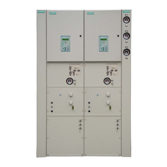
- Page 1 Type 8DA Extendable Fixed-Mounted Circuit-Breaker Switchgear up to 40.5 kV Single Busbar, Single-Pole Metal-Enclosed, Metal-Clad, Gas-Insulated Medium-Voltage Switchgear INSTALLTION INSTRUCTIONS Order No.: 861-9273.9 Revision: 03 fëëìÉW=MNJMPJOMMS...
- Page 2 Power Transmission and Distribution mitment or relationship. The Sales Contract contains the Carl-Benz-Str. 22 entire obligations of Siemens. The warranty contained in the contract between the parties is the sole warranty of D-60386 Frankfurt Siemens. Any statements contained herein do not cre- Germany ate new warranties or modify the existing warranty.
-
Page 3: Table Of Contents
Contents Safety instructions................4 Assembling panel connections supplied sepa- rately and filling circuit-breaker housings with SF6- Signal terms and definitions........ 4 gas ..............34 General instructions ..........4 Performing the power-frequency voltage test ..36 Due application............ 4 Installation work with SF6-gas after the power-fre- Qualified personnel .......... -
Page 4: Safety Instructions
p~ÑÉíó=áåëíêìÅíáçåë Safety instructions Signal terms and definitions DANGER! as used in these instructions, this means that personal injuries can occur if the relevant precautionary measures are not taken. Observe the safety instructions. ATTENTION! as used in these instructions, this means that damage to property or environment can occur if the relevant precautionary measures are not taken. -
Page 5: Qualified Personnel
p~ÑÉíó=áåëíêìÅíáçåë DANGER! The perfect and safe operation of this switchgear is conditional on: Observance of operating and installation instructions. Qualified personnel. Proper transportation and correct storage of the switchgear. Correct installation and commissioning. Diligent operation and maintenance. Observance of the instructions applicable at site for installation, operation and safety. -
Page 6: Installation
• Cleanliness: Switchgear room free of dirt and dust Installation dimensions and floor fixing To erect and install switchgear type 8DA, the place of installation (switchgear room) must have certain dimensions. Important data for erection and installation of the switchgear are, among other things, the room width, depth and height, as well as the necessary floor openings. - Page 7 fåëí~ää~íáçå Dimensions of the switch- gear room Room height h ≥ 2800 mm Fig. 1: Fig. 2: Room dimensions and wall distances =USNJVOTPKV=G=fkpq^iiqflk=fkpqor`qflkp=Ua^=G=oÉîáëáçå=MP...
- Page 8 fåëí~ää~íáçå Floor openings and fixing points Base frame Floor opening for control cables (Standard) Floor opening for control cables (end panels) Floor opening for control cables (gir- der on panel width) Floor opening for high-voltage cables Fixing points External edge of switchgear Fig.
-
Page 9: Intermediate Storage
fåëí~ää~íáçå Intermediate storage DANGER! Risk of injury and damage to the stored goods if the storage surface is overloaded or the transport units are stakked. Observe the load-bearing capacity of the floor. Do not stack the transport units. DANGER! Fire risk! No smoking. -
Page 10: Tools/Auxiliary Means
If there is no sufficient knowledge about professional regeneration of the packing: Ask for expert personnel via the competent Siemens Service Centre. Open the packings. Renew desiccant bags. -
Page 11: Installation And Fixing Material
• in a seaworthy crate (switchgear is sealed with desiccant bags in PE protection sheet- ing) • other packings in special cases. NOTE! The packing materials of 8DA switchgear can be disposed of as classified materials. Please observe the local regulations for disposal and environmental protection. Transport unit Transport units consist of: •... -
Page 12: Checking The Sf6-Gas Pressure
-gas pressure The housings of circuit-breakers and non-disconnectable voltage transformers of the switchgear type 8DA are filled with SF6-gas at the factory. To exclude any gas losses during transportation in the gas compartments filled at the factory, check the gas pressure indicators on the panels. - Page 13 Check the gas pressure in the compartments pre-filled at the factory on the associated gas pressure indicators. The temperature-dependent limit values must not be underflown. If the filling pressure is too low: Do not assemble the part of the switchgear concerned and inform the regional Siemens representative concerned. =USNJVOTPKV=G=fkpq^iiqflk=fkpqor`qflkp=Ua^=G=oÉîáëáçå=MP...
-
Page 14: Unloading Transport Units
fåëí~ää~íáçå Unloading transport units DANGER! Risk of injury due to transport units falling down. The transport units can slip off the transport tackle due to the high position of the centre of gravity. Do not stay under suspending loads. Avoid heavy movement of the load. Secure the fixing points of the ropes against slipping off. -
Page 15: Transporting The Units To The Place Of Installation
fåëí~ää~íáçå Fig. 8: Marking of transport holes Fig. 7: Position of transport holes Push the round bars into the transport holes at the front and at the rear. Attach ropes or chains at the ends of the round bars. Stretch the ropes or chains by lifting the transport tackle carefully. If the ropes or chains are touching the transport unit, use transport tackle / expander. -
Page 16: Setting Down The Transport Units At The Place Of Installation
fåëí~ää~íáçå Transporting the units with the pallets ATTENTION! Sensitive parts of the switchgear may be damaged during transport. Push the transport units only at the corners of the supporting frame. While pushing, take care not to damage any sensitive parts of the switchgear such as gas pipes, rupture diaphragms, shafts, etc. - Page 17 fåëí~ää~íáçå Fig. 9: Setting down from the narrow side of the floor Fig. 10: Setting down from the long side of the floor open- opening Transport unit Floor opening Door to the switchgear room Setting down the transport Precondition: The transport units must be standing on the roller pads / bars without units from the narrow side pallets.
- Page 18 fåëí~ää~íáçå ATTENTION! Without roller pads / bars underneath, the transport units are moved using hydraulic or lifting jacks. The transport units may be damaged. Apply auxiliary devices at floor level and only at the supporting frame of the transport units. Place boards under the points where auxiliary devices are applied.
-
Page 19: Aligning The Switchgear
fåëí~ää~íáçå Set down the transport unit carefully. Shift the transport unit with hydraulic jacks, lifting equipment or lifting jacks until it is exactly aligned on its mounting position. Prop the hydraulic equipment or jacks up at the surrounding walls. If the transport unit is still partly or totally standing on the shims, remove the shims and carefully set down the transport unit again. -
Page 20: Assembling The Switchgear
NOTE! The activities described hereafter must be carried out by qualified personnel who is familiar with installation of switchgear type 8DA. The switchgear assembling must be done by qualified personnel. The points the transport units are interconnected at are called panel joints hereafter. -
Page 21: Preparing Busbar Assembly
fåëí~ää~íáçå Preparing busbar assembly Removing the transport During transport, fixing brackets retain the busbars at the open flange connections of the blocks busbar housings. The fixing brackets are bolted together with the flanges of the busbar housings and the busbar ends. ATTENTION! If the switchgear is transported without transport blocks (fixing brackets), parts of the switchgear may be damaged. - Page 22 fåëí~ää~íáçå • Make-proof busbar earthing switch • Top-mounted busbar sectionaliser In these cases, the busbar joints are not accessible anymore after the transport units have been installed. For this reason, the busbar sections must be re-assembled from the panel on the left of the panel joint to the panel on the right before assembly.
-
Page 23: Installing The Transport Unit
Damages and pollution will cause leaks. If any external contact surfaces or grooves are damaged: Inform the Siemens Service Centre and co-ordinate the elimination of damages. Apply a thin film of the supplied mounting paste on the external contact surfaces of the flanges and the O-rings (sealing rings). - Page 24 fåëí~ää~íáçå ATTENTION! Without roller pads / bars underneath, the transport units are moved using hydraulic or lifting jacks. The transport units may be damaged. Apply auxiliary devices at floor level and only at the supporting frame of the transport units. Place boards under the points where auxiliary devices are applied.
- Page 25 fåëí~ää~íáçå Busbar housing Compensator Insulating ring (thickness: 18 mm) Insulating ring (thickness: 4 mm) Fig. 16: Short busbar housing with compensator Fig. 17: Long busbar housing with insulating joint On the observer's command, push the transport unit to be connected towards the already mounted one using the lifting gear.
- Page 26 fåëí~ää~íáçå Bolting the flanges of the busbar housings together Current transformer mounting plate Flange Insulating ring Compensator Insulating sleeve Fig. 18: Flange connections with insulating sleeve ATTENTION! Sensitive parts of the switchgear may be damaged during installation work at the busbar and the busbar housings.
-
Page 27: Installing Further Transport Units
fåëí~ää~íáçå Check whether the busbars have been pre-assembled with a post insulator Align busbar and post insulator horizontally with each other using the clearance of the busbar hole. Align the busbars and the links so that the busbar sections are in line and the fixing bolts will fit through the holes. - Page 28 fåëí~ää~íáçå Correcting contact overlap- ping of disconnector con- tacts Hexagonal sleeve of the discon- nector coupling rod Lock nuts Fig. 19: Disconnector coupling rod Undo the lock nuts at the hexagonal sleeve of the disconnector coupling rod Modify the length of the disconnector coupling rod by turning the hexagonal sleeve until the contact blades hold the fixed contacts centrally in the CLOSED position.
- Page 29 fåëí~ää~íáçå Connecting plate (rear) Connecting links (front) Fig. 20: Bolting supporting frames together Align adjacent connecting links at the supporting frames. Holes must be in line. Bolt transport units together at the front connecting links using three bolts M8x35 (tightening torque 20 Nm), and at the rear connecting plate using three coach bolts M10x20 (tightening torque 40 Nm).
-
Page 30: Sioning
fåëí~ää~íáçå Undo right-hand bolt at the joint and fold the earthing busbar section to the left into horizontal position. Bolt the earthing busbar section together with the earthing busbar of the next transport unit using 2 bolts. Tightening torque: 70 Nm. Refit the removed bolt at the joint and tighten the two bolts at the joint. - Page 31 fåëí~ää~íáçå Preparing the busbar run for filling gas Fig. 22: Desiccant bags in the gas compartments (position identified in the illustration by black squares; on the switchgear, with the inscription "Filter" on the outside) Item no. Designation Desiccant bags Busbar housing, left end panel 2 x 250 g Busbar housing, with post insulator 1 x 450 g...
- Page 32 fåëí~ää~íáçå ATTENTION! In the ambient air, the desiccant bags lose their effectiveness rapidly and cannot be used anymore. Use only desiccant bags whose packing is not damaged and whose humidity indicators in the packing are blue. Do not use desiccant bags if the humidity indicators are pink. After opening the packings, mount the desiccant bags in the gas compartment within 30 minutes and close the gas compartment hermetically.
- Page 33 fåëí~ää~íáçå Pressure indicator for busbar housings (number according to design of busbar sys- tem) Gas filling socket for busbar housings (num- ber according to design of busbar system) Pressure indicator for circuit-breaker hou- sing Gas filling socket for circuit-breaker housing Fig.
-
Page 34: Assembling Panel Connections Supplied Separately And Filling Circuit-Breaker Housings With Sf 6 -Gas
fåëí~ää~íáçå The limit value indicators on the pressure indicator of the busbar run have been pre- adjusted at the factory. Check the limit pressures according to the table and the graphics, and correct with the supplied square socket spanner in case of deviations. Completing the assembly of Fill all other busbar runs as described above (see Page 30, "Completing busbar further busbar runs and fill-... - Page 35 fåëí~ää~íáçå Repeat the above work operations for all other panel connections in the same panel. Replacing desiccant bags The desiccant bags are located behind the cover of the rupture diaphragm at the side of in the circuit-breaker hous- the circuit-breaker housing. The cover has the inscription "Filter". ings Cover of rupture diaphragm Fig.
-
Page 36: Performing The Power-Frequency Voltage Test
fåëí~ää~íáçå Evacuating the circuit- The circuit-breaker housings of one panel form a common gas compartment. Before breaker housings with the filling SF -gas in, the air must be removed from the circuit-breaker housings (evacuation). vacuum pump The pressure indicator and the maintenance valve for the circuit-breaker housings of one panel are located on the right side of the housing front (see Fig. - Page 37 fåëí~ää~íáçå ATTENTION! If the rated short-duration power-frequency withstand voltage test is performed incorrectly, the switchgear may be damaged. Do not perform a rated short-duration power-frequency withstand voltage test without the manufacturer’s assistance. ATTENTION! Already mounted non-disconnectable inductive voltage transformers which are not suitable for tests at 80%-values according to IEC 60044-2 will be damaged during the rated short-duration power-frequency withstand voltage test.
-
Page 38: Quency Voltage Test
fåëí~ää~íáçå Installation work with SF -gas after the power-frequency volt- age test If a rated short-duration power-frequency withstand voltage test has to be performed at site, the work with sulphur hexafluoride gas (SF ) described in this section must be performed after the test. -
Page 39: Removing And Installing Non-Disconnectable Busbar Voltage Transformers
fåëí~ää~íáçå Removing and installing non-disconnectable busbar voltage transformers If a power-frequency voltage test must be performed before putting the switchgear into operation, already mounted non-disconnectable inductive voltage transformers which are not suitable for tests at 80%-values according to IEC 60044-2 must be removed. The work operations described hereafter apply to all voltage transformer types. - Page 40 fåëí~ää~íáçå Removing voltage transformer type 4MT3 Handle Voltage transformer 4MT3 Adapter plate Distance sleeves Voltage transformer mounting plate Busbar housing Outside-cone bushing Hole with setnut for press-out bolts Fig. 26: Busbar voltage transformer 4MT3 (shown without cover) Remove the cover of the voltage transformer. Remove the fixing bolts of the adapter plate.
- Page 41 fåëí~ää~íáçå Protect the connection socket of the voltage transformer against damages and pollution. Close the outside-cone bushing at the panel with surge-proof covers. Removing voltage transformer type 4MU1 Voltage transformer 4MU1 Retaining angle with crane eyes Voltage transformer mounting plate Busbar housing Distance sleeves Outside-cone bushing...
- Page 42 fåëí~ää~íáçå ATTENTION! Risk of injury! The voltage transformer type 4MU1 has a weight of approx. 50 kg. Secure the voltage transformer against falling down. If necessary, transport the voltage transformer with several persons or with suitable aids. Remove the voltage transformer upwards together with the retaining angles by means of the steel rods.
-
Page 43: Installing Non-Disconnectable Busbar Voltage Transformers
fåëí~ää~íáçå ATTENTION! Risk of injury! While being removed from the bushing, the voltage transformer can detach suddenly. Remove the voltage transformer upwards as uniformly as possible. Do not use excessive force. ATTENTION! Risk of injury! The voltage transformer type 4MT6 has a weight of approx. 60 kg. Secure the voltage transformer against falling down. - Page 44 fåëí~ää~íáçå ATTENTION! Risk of partial discharges at the voltage transformer bushings due to pollution. Clean all bushings at the panel and at the voltage transformer carefully before starting installation work. Observe extreme cleanliness while working. Preparing installation for Isolate and earth the busbar. 4MT3 and 4MU1 Verify safe isolation from supply.
- Page 45 fåëí~ää~íáçå Voltage transformer type 4MU1: If not yet pre-assembled, mount the fixing brackets on the voltage transformer. To let excess air out of the plug connection while mounting the voltage transformers, fit a nylon thread or a cable strap into the inside cone of the voltage transformer. Preparing installation for Isolate and earth the busbar.
-
Page 46: Final Installation Work
fåëí~ää~íáçå Final installation work 12.1 Mounting cables with plugs ATTENTION! The dust-proof caps supplied on the sockets of the multiple panel connections do not provide sufficient shock protection. Close unused sockets of multiple panel connections with dummy plugs. Proceed according to the installation instructions of the corresponding plug manufacturer. -
Page 47: Checking The Circuits Of The Low-Voltage Equipment
After commissioning, check the gas pressures daily for a period of two weeks. If the sure gas pressures drop within this period of time, please inform the Siemens Service Centre. After this period of time, check the gas pressures according to the maintenance instructions. -
Page 48: Commissioning
fåëí~ää~íáçå Commissioning 14.1 Checking the installation work Carry out a final check to make sure that all installation work has been performed according to these installation instructions. 14.2 Test operation Read the operating instructions before the test operation. Test operation helps you to verify the perfect operation of the switchgear without high voltage. -
Page 49: Checking The Accessories
Correcting circuit diagrams Note any modifications which may have been made during installation or commissioning in the supplied circuit diagrams. Send the corrected documentation to the responsible Siemens Service Centre so that the modifications can be included. 14.5 Instructing the operating personnel Hand over the operating instructions to the operating personnel before commissioning. -
Page 50: Index
Index Installation, non-disconnectable busbar voltage trans- Information to Siemens before delivery ......6 formers ................ 39 Installation dimensions..........6 Non-disconnectable busbar voltage transformers, instal- Installation material ............11 lation ................39 Installation with gas work ........... 30 Non-disconnectable busbar voltage transformers, removal ................ - Page 51 transport damage ............12 Voltage transformer 4MT3 ...........40 Transport unit..............11 Voltage transformer 4MT3, removal......40 Transport unit, erecting..........11 Voltage transformer 4MT6 ...........42 Transport unit, installation..........23 Voltage transformer 4MT6, removal......42 Transport unit, unloading ..........11 Voltage transformer 4MU1...........41 Voltage transformer 4MU1, removal......41 Vacuum pump .............
- Page 52 Impressum Power Transmission and Distribution Medium Voltage Schaltanlagenwerk Frankfurt Carl-Benz-Str. 22 D-60386 Frankfurt © Siemens AG 2006...