
Related Manuals for Huawei UPS5000-E-30 kVA-FM


Summary of Contents for Huawei UPS5000-E-30 kVA-FM
- Page 1 UPS5000-E-(30 kVA–120 kVA)-FM User Manual Issue Date 2022-01-30 HUAWEI TECHNOLOGIES CO., LTD.
- Page 2 Notice The purchased products, services and features are stipulated by the contract made between Huawei and the customer. All or part of the products, services and features described in this document may not be within the purchase scope or the usage scope. Unless otherwise specified in the contract, all statements, information, and recommendations in this document are provided "AS IS"...
-
Page 3: About This Document
Indicates a hazard with a low level of risk which, if not avoided, could result in minor or moderate injury. Issue 03 (2022-01-30) Copyright © Huawei Technologies Co., Ltd. - Page 4 Issue 03 (2022-01-30) Updated the monitoring user interfaces. Issue 02 (2020-11-10) Adapted the UPS to SmartLi and updated the monitoring user interfaces. Issue 01 (2020-04-27) This is the first official release. Issue 03 (2022-01-30) Copyright © Huawei Technologies Co., Ltd.
-
Page 5: Table Of Contents
2.3.4 Power Distribution Module............................28 2.3.5 Control Module.................................. 28 2.3.5.1 Overview................................... 28 2.3.5.2 ECM..................................... 29 2.3.5.3 Dry Contact Card................................31 2.3.5.4 Monitoring Interface Card............................34 2.3.6 MDU....................................... 38 2.4 Typical Configurations................................. 40 Issue 03 (2022-01-30) Copyright © Huawei Technologies Co., Ltd. - Page 6 4.1.2.2 Settings Wizard................................90 4.1.3 Starting the Inverter................................. 92 4.1.4 Powering On Loads................................93 4.1.5 (Optional) Setting Parameters for the BCB Box..................... 93 4.2 Shutting Down and Powering Off the UPS........................94 Issue 03 (2022-01-30) Copyright © Huawei Technologies Co., Ltd.
- Page 7 7.5 Mains Input Electrical Specifications........................... 122 7.6 Bypass Input Electrical Specifications.......................... 122 7.7 Battery Electrical Specifications............................. 123 7.8 Output Electrical Specifications............................. 124 7.9 System Electrical Specifications............................. 125 A (Optional) TN-C System Application................126 B User Interface........................127 Issue 03 (2022-01-30) Copyright © Huawei Technologies Co., Ltd.
- Page 8 UPS5000-E-(30 kVA–120 kVA)-FM User Manual Contents C Alarm List..........................128 D Acronyms and Abbreviations................... 129 Issue 03 (2022-01-30) Copyright © Huawei Technologies Co., Ltd.
-
Page 9: Safety Information
● Failure to follow the operation instructions and safety precautions on the product and in this document ● Equipment damage due to force majeure, such as earthquakes, fire, and storms Issue 03 (2022-01-30) Copyright © Huawei Technologies Co., Ltd. - Page 10 ● Keep irrelevant people away from the equipment. Only operators are allowed to access the equipment. ● Use insulated tools or tools with insulated handles, as shown in the following figure. Issue 03 (2022-01-30) Copyright © Huawei Technologies Co., Ltd.
- Page 11 Do not change the structure or installation sequence of equipment without permission. ● Do not touch a running fan with your fingers, components, screws, tools, or boards before the fan is powered off or stops running. Issue 03 (2022-01-30) Copyright © Huawei Technologies Co., Ltd.
-
Page 12: Personnel Requirements
Do not operate the equipment in the absence of a properly installed ground conductor. ● Ensure that the equipment is connected permanently to the protective ground. Before operating the equipment, check its electrical connection to ensure that it is securely grounded. Issue 03 (2022-01-30) Copyright © Huawei Technologies Co., Ltd. - Page 13 0°C. Handle cables with caution, especially at a low temperature. – Cables stored at subzero temperatures must be stored at room temperature for at least 24 hours before they are laid out. Issue 03 (2022-01-30) Copyright © Huawei Technologies Co., Ltd.
-
Page 14: Installation Environment Requirements
Install the equipment in an area far away from liquids. Do not install it under areas prone to condensation, such as under water pipes and air exhaust vents, or areas prone to water leakage, such as air conditioner vents, ventilation Issue 03 (2022-01-30) Copyright © Huawei Technologies Co., Ltd. - Page 15 Any violations must be promptly pointed out by the site manager or safety supervisor and the involved personnel should be prompted for correction. Personnel who fail to stop violations will be forbidden from working. Issue 03 (2022-01-30) Copyright © Huawei Technologies Co., Ltd.
-
Page 16: Mechanical Safety
Ensure that the wider end of the ladder is at the bottom, or protective measures have been taken at the bottom to prevent the ladder from sliding. Issue 03 (2022-01-30) Copyright © Huawei Technologies Co., Ltd. - Page 17 When pulling the equipment out of a cabinet, be aware of unstable or heavy objects on the cabinet to prevent injury. ● Be cautious to avoid injury when moving heavy objects. Issue 03 (2022-01-30) Copyright © Huawei Technologies Co., Ltd.
-
Page 18: Equipment Operating Environment
The UPS operating environment must meet the requirements for the climate indicator, mechanically active substance indicator, and chemically active substance indicator in ETSI EN 300 019-1 class 3.6. Issue 03 (2022-01-30) Copyright © Huawei Technologies Co., Ltd. - Page 19 UPS is connected to a backfeed protection card. Disconnect the backfeed protection card from the UPS before operating the UPS. Issue 03 (2022-01-30) Copyright © Huawei Technologies Co., Ltd.
-
Page 20: Battery Safety
● Dispose of waste batteries in accordance with local laws and regulations. Do not dispose of batteries as household waste. If a battery is disposed of improperly, it may explode. Issue 03 (2022-01-30) Copyright © Huawei Technologies Co., Ltd. - Page 21 ● To prevent fire or corrosion, ensure that flammable gas (such as hydrogen) is properly exhausted for lead-acid batteries. Lead-acid batteries in use emit flammable gas. Ensure that batteries are kept in a well-ventilated area and take preventive measures against fire. Issue 03 (2022-01-30) Copyright © Huawei Technologies Co., Ltd.
- Page 22 Use batteries within the allowed temperature range. Otherwise, the battery performance and safety will be compromised. ● Do not throw a lithium battery in fire. ● When maintenance is complete, return the waste lithium battery to the maintenance office. Issue 03 (2022-01-30) Copyright © Huawei Technologies Co., Ltd.
-
Page 23: Others
UPS output voltage level or frequency. Doing so may affect the power supply to equipment. ● Exercise caution when setting battery parameters. Incorrect settings will affect the power supply and battery lifespan. Issue 03 (2022-01-30) Copyright © Huawei Technologies Co., Ltd. -
Page 24: Overview
5000 family E series subcategory Output 120K: output capacity of 120 kVA (compatible with 90 capacity kVA, 60 kVA, and 30 kVA) Configuration F: full configuration of switches type M: modular Issue 03 (2022-01-30) Copyright © Huawei Technologies Co., Ltd. -
Page 25: Working Principle
In normal mode, the rectifier converts AC power into DC power, and then the inverter converts the DC power into high-precision AC outputs. The conversions protect loads from interference such as input harmonics, glitches, and voltage transients. Issue 03 (2022-01-30) Copyright © Huawei Technologies Co., Ltd. -
Page 26: Bypass Mode
In bypass mode, loads are powered by the bypass module. The bypass power supply is not protected by the UPS and therefore is prone to the mains outage, abnormal AC voltage waveform, or abnormal frequency. Issue 03 (2022-01-30) Copyright © Huawei Technologies Co., Ltd. -
Page 27: Battery Mode
If the mains input is abnormal or the rectifier becomes abnormal, the UPS transfers to battery mode. The power module obtains DC power from batteries, and the power is converted into AC output by the inverter. Issue 03 (2022-01-30) Copyright © Huawei Technologies Co., Ltd. -
Page 28: Maintenance Bypass Mode
2.2.2.4 Maintenance Bypass Mode When the UPS works in maintenance bypass mode, the current flows through the maintenance bypass instead of the power module. You can maintain the circuit inside the cabinet. Issue 03 (2022-01-30) Copyright © Huawei Technologies Co., Ltd. -
Page 29: Eco Mode
UPS transfers from bypass mode to inverter mode. In bypass mode or normal mode, the rectifier keeps working and charges batteries using a charger. The ECO mode delivers a high efficiency. Issue 03 (2022-01-30) Copyright © Huawei Technologies Co., Ltd. -
Page 30: Product Introduction
Figure 2-7 UPS conceptual diagram in ECO mode NO TE Manual startup is required to ensure that the inverter is in standby state and the power flow has reached the inverter. 2.3 Product Introduction Issue 03 (2022-01-30) Copyright © Huawei Technologies Co., Ltd. -
Page 31: Structure
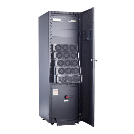
(4) Bypass input switch bypass switch (5) Mains input switch (6) Surge protective (7) Control module (8) Bypass module module (optional) (9) Power modules (10) Monitor display (11) Document holder module (MDU) Issue 03 (2022-01-30) Copyright © Huawei Technologies Co., Ltd. -
Page 32: Power Module
(blinking at 0.5 Hz, on for 1s and off for interval 1s). ● The inverter is not started (blinking at 0.2 Hz, on for 2.5s and off for 2.5s). Issue 03 (2022-01-30) Copyright © Huawei Technologies Co., Ltd. - Page 33 Dimensions (H x W x D): 86 mm x 442 mm x 620 mm ● Weight: < 21 kg ● Rated output capacity: 30 kVA/30 kW ● Power density: 20.64 W/inch Issue 03 (2022-01-30) Copyright © Huawei Technologies Co., Ltd.
-
Page 34: Bypass Module
2.5s and off for 2.5s). interval Blinking The bypass is not configured or the DSP at short software is being upgraded (blinking at 4 Hz, interval on for 0.125s and off for 0.125s). Issue 03 (2022-01-30) Copyright © Huawei Technologies Co., Ltd. - Page 35 The power supply is switched to the bypass manually. Specifications ● Dimensions (H x W x D): 130 mm x 420 mm x 500 mm ● Weight: 19 kg ● Rated output capacity: 200 kVA Issue 03 (2022-01-30) Copyright © Huawei Technologies Co., Ltd.
-
Page 36: Power Distribution Module
(from left to right). The four cards are hot swappable. One subrack is reserved above the dry contact card. A backfeed protection card or dry contact extended card can be inserted into this subrack. Issue 03 (2022-01-30) Copyright © Huawei Technologies Co., Ltd. -
Page 37: Ecm
The control module consists of two energy control modules (ECMs) in active/ standby mode. Figure 2-13 ECM Table 2-4 Ports on the ECM Silk Screen Description PARALLEL The PARALLEL port transmits parallel signals between racks. Issue 03 (2022-01-30) Copyright © Huawei Technologies Co., Ltd. - Page 38 ● Provides module running information for the MDU. ● Controls the running of a single UPS and a parallel system, and reports the UPS status information to other monitoring modules. Issue 03 (2022-01-30) Copyright © Huawei Technologies Co., Ltd.
-
Page 39: Dry Contact Card
Table 2-6 Ports on the dry contact card Silk Screen Description Status Initial Status Port for detecting ● Connected: battery Disconnected battery grounding grounding fault faults ● Disconnected: no battery grounding Port for signal fault ground Issue 03 (2022-01-30) Copyright © Huawei Technologies Co., Ltd. - Page 40 Port for signal STATUS_0V ground SWITCH Port for monitoring ● Disconnected: Disconnected STATUS_MT the maintenance circuit breaker ON circuit breaker ● Connected: circuit breaker OFF SWITCH Port for signal STATUS_0V ground Issue 03 (2022-01-30) Copyright © Huawei Technologies Co., Ltd.
- Page 41 The dry contact card allows the UPS to detect and manage the switch status of the battery system (including the external battery switch) and implement remote EPO. Specifications ● Hot-swappable ● 0.5 U high Issue 03 (2022-01-30) Copyright © Huawei Technologies Co., Ltd.
-
Page 42: Monitoring Interface Card
Table 2-7 Monitoring interface card Port Silk Description Screen DO_1 ● DO_1, DO_2, DO_3, and DO_4 indicate alarm outputs. The default values are Critical alarm, Minor alarm, Bypass mode, and Battery mode, respectively. DO_2 Issue 03 (2022-01-30) Copyright © Huawei Technologies Co., Ltd. - Page 43 ● Signal cables must be double-insulated twisted cables. If the cable length is 25–50 m, the cross-sectional area must be 0.5–1.5 mm ● RS485 cables and FE cables must be shielded cables. Figure 2-17 Figure 2-18 are recommended wiring methods for DO ports. Issue 03 (2022-01-30) Copyright © Huawei Technologies Co., Ltd.
- Page 44 UPS5000-E-(30 kVA–120 kVA)-FM User Manual 2 Overview Figure 2-17 Wiring method 1 Figure 2-18 Wiring method 2 Figure 2-19 COM1 pins Table 2-8 COM1 pin definition Description RS485- RS485+ 12V_PORT Issue 03 (2022-01-30) Copyright © Huawei Technologies Co., Ltd.
- Page 45 UPS5000-E-(30 kVA–120 kVA)-FM User Manual 2 Overview Figure 2-20 COM2 pins Table 2-9 COM2 pin definition Description RS485+ RS485- RS485+ RS485- CANH0 CANL0 Figure 2-21 RS485 pins Issue 03 (2022-01-30) Copyright © Huawei Technologies Co., Ltd.
-
Page 46: Mdu
RS485+. Twist cables to pin 2 and pin 5 into one cable and then connect it to RS485–. 2.3.6 MDU Appearance Figure 2-22 MDU (1) Status indicator (2) LCD touchscreen Issue 03 (2022-01-30) Copyright © Huawei Technologies Co., Ltd. - Page 47 Figure 2-23 MDU ports Table 2-12 Port description Port Name Description MUS05A Connects to the MDU and monitoring interface card (DB26) Network port Reserved RS485_1 Reserved FE_1 Reserved FE_2 Reserved Issue 03 (2022-01-30) Copyright © Huawei Technologies Co., Ltd.
-
Page 48: Typical Configurations
In addition to common parallel system advantages, the dual- bus system also provides outstanding availability and eliminates bottleneck failures. However, configuration of the dual-bus system is complex. Issue 03 (2022-01-30) Copyright © Huawei Technologies Co., Ltd. -
Page 49: Single Ups
An optional static transfer switch (STS) can be installed to start the bus synchronization controller (BSC). The UPS systems work in normal mode or bypass mode. Issue 03 (2022-01-30) Copyright © Huawei Technologies Co., Ltd. -
Page 50: Optional Components
SPD circuit breakers module and SPDs, which provide surge protection for mains input and bypass input respectively. The surge protective capacity reaches 5 kA if a surge protective module is configured. Issue 03 (2022-01-30) Copyright © Huawei Technologies Co., Ltd. - Page 51 NO TE The ECM expansion subrack does not support onsite installation. If you require this optional component, specify it when you purchase the device and the component will be preinstalled. Issue 03 (2022-01-30) Copyright © Huawei Technologies Co., Ltd.
-
Page 52: Installation
Ensure that the floor or installation support can bear the weight of the UPS5000, batteries, and battery racks. The weight of batteries and battery racks depends on the UPS configuration for the site. Issue 03 (2022-01-30) Copyright © Huawei Technologies Co., Ltd. -
Page 53: Installation Environment
Do not install the UPS in environments with conductive metal scraps in the air. ● The optimal operating temperatures for valve-regulated lead-acid batteries (VRLA batteries) are 20–30°C. Operating temperatures higher than 30°C Issue 03 (2022-01-30) Copyright © Huawei Technologies Co., Ltd. -
Page 54: Installation Clearances
Figure 3-2 Reserved clearances (unit: mm) 3.1.2 Tools and Instruments CA UTION Insulate installation tools to prevent electric shocks. Prepare the following tools and meters indicated in Table 3-1 for installation. Issue 03 (2022-01-30) Copyright © Huawei Technologies Co., Ltd. - Page 55 Crimping tools Wire stripper Electric hydraulic pliers Clamp meter Multimeter Cable tie Level instrument Insulation tape Cotton cloth Label Electrician's knife Electrostatic Protective gloves Insulated gloves Insulation discharge (ESD) protective shoes gloves Issue 03 (2022-01-30) Copyright © Huawei Technologies Co., Ltd.
-
Page 56: Preparing Power Cables
380 V (line voltage). Table 3-2 Recommended cross-sectional areas for power cables Item Specifications 30 kVA 60 kVA 90 kVA 120 kVA Mains Mains input current (A) input Issue 03 (2022-01-30) Copyright © Huawei Technologies Co., Ltd. - Page 57 Battery Nominal discharge input current (A) (lead- Maximum discharge acid current (A) battery) Recommende 3 x 16 3 x 50 3 x 70 3 x 120 d cross- sectional area Issue 03 (2022-01-30) Copyright © Huawei Technologies Co., Ltd.
- Page 58 Bolt Bolt Hole Bolt Length Torque Method Specifications Diameter Mains Crimped OT 11 mm 30 mm 26 N·m input terminals Bypass Crimped OT 11 mm 30 mm 26 N·m input terminals Issue 03 (2022-01-30) Copyright © Huawei Technologies Co., Ltd.
- Page 59 250 A/3P breaker Bypass input circuit 250 A/3P breaker Downstream output 250 A/3P circuit breaker a: recommended when the short-circuit current where the switch is located is less than 36 kA Issue 03 (2022-01-30) Copyright © Huawei Technologies Co., Ltd.
-
Page 60: Transportation, Unpacking, And Checking
Step 2 Check the UPS packing. Step 3 Hold the sliding plate steady. Cut and remove the binding tapes. Put down the sliding plate gently. See Figure 3-3. Figure 3-3 Removing binding tapes Issue 03 (2022-01-30) Copyright © Huawei Technologies Co., Ltd. - Page 61 Step 7 After confirming that the UPS is intact, remove the front and rear L-shaped brackets that secure the UPS to the pallet, and secure the sliding plate to the pallet using the two M12 bolts removed before. Figure 3-5 Removing the L-shaped brackets Issue 03 (2022-01-30) Copyright © Huawei Technologies Co., Ltd.
- Page 62 Ensure that the two screws are installed reliably. Otherwise, the sliding plate may shift when the UPS slides down. Step 8 Raise the four anchor bolts to the highest position using an adjustable wrench, as shown in Figure 3-7. Issue 03 (2022-01-30) Copyright © Huawei Technologies Co., Ltd.
-
Page 63: Installing A Single Ups
----End 3.3 Installing a Single UPS 3.3.1 Installing a UPS Cabinet Secured Installation Step 1 Determine the cabinet installation position. Draw mounting holes in the installation position according to the drawing. Issue 03 (2022-01-30) Copyright © Huawei Technologies Co., Ltd. - Page 64 NO TICE Knock the expansion bolt into the hole until the expansion sleeve completely fits into the hole. The expansion sleeve must be completely buried under the ground to facilitate subsequent installation. Issue 03 (2022-01-30) Copyright © Huawei Technologies Co., Ltd.
- Page 65 Step 4 (Optional) If the castors of the UPS need to be lifted from the ground, perform steps Step 1 Step 2 Unsecured Installation. Step 5 Remove the rear panel of the cabinet, and then open the front door. Issue 03 (2022-01-30) Copyright © Huawei Technologies Co., Ltd.
- Page 66 Step 6 Remove the four plugs from the bottom of the cabinet (two at the front and two at the rear). Figure 3-12 Removing plugs Step 7 Insert four M12x115 expansion bolts into the expansion bolt holes in the floor, and tighten the expansion bolts in the direction. Issue 03 (2022-01-30) Copyright © Huawei Technologies Co., Ltd.
- Page 67 Figure 3-14. Figure 3-14 Castors adjustment Step 2 Check the cabinet levelness using a level. If the cabinet is not level, wrench the anchor bolts. ----End Issue 03 (2022-01-30) Copyright © Huawei Technologies Co., Ltd.
-
Page 68: Installing Batteries
Figure 3-15 Antiseismic kit mounting hole positions Step 2 Secure two antiseismic kits to the front and rear of the cabinet using twelve M5x16 screws and four M12 screws. Issue 03 (2022-01-30) Copyright © Huawei Technologies Co., Ltd. -
Page 69: Connecting An Ambient T/H Sensor
Figure 3-17 Securing the antiseismic kits to the floor ----End 3.3.3.2 Connecting an Ambient T/H Sensor Procedure Step 1 Connect the RJ11 port on the ambient T/H sensor to the COM1 port on the monitoring interface card. Issue 03 (2022-01-30) Copyright © Huawei Technologies Co., Ltd. -
Page 70: Connecting The Ibat
Figure 3-19 COM2 port ----End 3.3.3.4 Installing a Battery Grounding Failure Detector Procedure Step 1 Install a battery grounding failure detector. For the installation method, see UPS5000 Battery Grounding Failure Detector User Manual . Issue 03 (2022-01-30) Copyright © Huawei Technologies Co., Ltd. -
Page 71: Ups Cable Connection Reference
Step 3 Pull the marked cable out of the cabinet, cut the cable from the marked position, strip the cable, and crimp a terminal. Issue 03 (2022-01-30) Copyright © Huawei Technologies Co., Ltd. -
Page 72: Routing Cables
Step 1 Ensure the maintenance bypass switch is OFF. Open the front door, remove the front cover, and remove covers from the top of the cabinet based on the site requirements. Issue 03 (2022-01-30) Copyright © Huawei Technologies Co., Ltd. - Page 73 UPS5000-E-(30 kVA–120 kVA)-FM User Manual 3 Installation Figure 3-22 Removing the cover Issue 03 (2022-01-30) Copyright © Huawei Technologies Co., Ltd.
- Page 74 (1) Battery input terminals (+, N, –) (2) Mains input terminals (1L1–1L3, N) (3) Bypass input terminals (2L1–2L3, N) (4) Output terminals (U, V, W, N) Step 2 Connect the ground cable. Issue 03 (2022-01-30) Copyright © Huawei Technologies Co., Ltd.
- Page 75 User Manual 3 Installation Figure 3-24 Grounding Step 3 Route power cables. ● Two power sources Remove the copper bar between mains and bypass input terminals. Figure 3-25 Removing copper bars Issue 03 (2022-01-30) Copyright © Huawei Technologies Co., Ltd.
- Page 76 If the mains input and bypass input share a power source, you do not need to remove the copper bar between the mains and bypass input terminals or connect the bypass input power cable. Step 4 Route signal cables. Bind cables to the cabinet. Issue 03 (2022-01-30) Copyright © Huawei Technologies Co., Ltd.
-
Page 77: Bottom Cable Routing
Route cables for the UPS from inside out. Procedure Step 1 (Optional) Determine the installation position for the cable entry cabinet, and draw mounting holes in the installation position based on drawings. Issue 03 (2022-01-30) Copyright © Huawei Technologies Co., Ltd. - Page 78 Step 3 Adjust the anchor bolts of the cable entry cabinet to make it flush with the UPS cabinet. Step 4 Install equipotential plate mounting kits on the same horizontal plane of the UPS cabinet and cable entry cabinet. Issue 03 (2022-01-30) Copyright © Huawei Technologies Co., Ltd.
- Page 79 Figure 3-30 Installing equipotential plate mounting kits (1) Side panel (2) Cable trough Step 5 Place the cable entry cabinet on the right of the UPS cabinet. Step 6 Install the front and rear connecting kits. Issue 03 (2022-01-30) Copyright © Huawei Technologies Co., Ltd.
- Page 80 Step 7 (Optional) Secure the cable entry cabinet to the ground. NO TE For details about how to secure the cable entry cabinet, see Secured Installation 3.3.1 Installing a UPS Cabinet. Step 8 Install an equipotential plate. Figure 3-32 Equipotential plate Issue 03 (2022-01-30) Copyright © Huawei Technologies Co., Ltd.
- Page 81 Remove the two large covers from the bottom of the cable entry cabinet, drill holes in them based on site requirements, and install them on the positions where the small covers were placed. Issue 03 (2022-01-30) Copyright © Huawei Technologies Co., Ltd.
- Page 82 For the screw specifications and torque used for connecting cables in a bottom cable routing scenario, refer to the top cable routing scenario. This section only shows the cable routes in the bottom cable routing scenario. Issue 03 (2022-01-30) Copyright © Huawei Technologies Co., Ltd.
- Page 83 UPS5000-E-(30 kVA–120 kVA)-FM User Manual 3 Installation Figure 3-36 Connecting cables Step 12 Remove the signal cable trough cover from the cable entry cabinet. Issue 03 (2022-01-30) Copyright © Huawei Technologies Co., Ltd.
- Page 84 Step 13 Connect the signal cable. (Route the signal cable out of the UPS cabinet through the cable hole on the top, and then into the cable entry cabinet through the cable hole on the top of that cabinet.) Issue 03 (2022-01-30) Copyright © Huawei Technologies Co., Ltd.
-
Page 85: Connecting A Remote Epo Switch
UPS mains input. To power off the UPS completely, open the front-end input switch when triggering EPO. Connect the requisite EPO switch to UPS dry contacts. ● Figure 3-39 shows the cable connections for an NC EPO switch. Issue 03 (2022-01-30) Copyright © Huawei Technologies Co., Ltd. -
Page 86: Connecting Communications Cables
Step 1 Connect the external network management device to the RS485 port of the monitoring interface card. Step 2 Connect the network port on a PC to the FE port of the monitoring interface card. ----End 3.4 Installing a Parallel System Issue 03 (2022-01-30) Copyright © Huawei Technologies Co., Ltd. -
Page 87: Installing The Upss
UPSs and then tighten the screws on the kit, as shown in Figure 3-41. Figure 3-41 Installing connecting kits NO TE Connecting kits also need to be installed at the rear of the UPSs. ----End Issue 03 (2022-01-30) Copyright © Huawei Technologies Co., Ltd. -
Page 88: Connecting Power Cables
1+1 parallel system in a typical scenario. Figure 3-42 Figure 3-43 show the typical conceptual diagram and cable connections for a 1+1 parallel system. Figure 3-42 Conceptual diagram of a 1+1 parallel system Issue 03 (2022-01-30) Copyright © Huawei Technologies Co., Ltd. - Page 89 Figure 3-44 shows a typical conceptual diagram for a dual-bus system, and Figure 3-45 shows the cable connections for this system. Figure 3-44 Conceptual diagram of a dual-bus system Issue 03 (2022-01-30) Copyright © Huawei Technologies Co., Ltd.
-
Page 90: Connecting Signal Cables
Step 1 Connect the parallel ports on the UPSs using parallel cables to form a loop. ● Figure 3-46 shows the topology diagram for the N+X parallel system and Figure 3-47 shows the cable connections for this system. Issue 03 (2022-01-30) Copyright © Huawei Technologies Co., Ltd. - Page 91 +X parallel system ● In a dual-bus system, you need to connect cables to BSC ports on the UPSs. Figure 3-48 shows the cable connections for a dual-bus system containing two master systems. Issue 03 (2022-01-30) Copyright © Huawei Technologies Co., Ltd.
-
Page 92: Verifying The Installation
UPS may be damaged. Table 3-5 Check items and acceptance criteria Item Acceptance Criteria UPS installation The UPS is securely installed and does not tilt due to vibration. Issue 03 (2022-01-30) Copyright © Huawei Technologies Co., Ltd. - Page 93 4. Ensure that there is no foreign matter on the bottom plate of the cabinet. 5. Ensure that there is no foreign matter on the rear module subrack. Issue 03 (2022-01-30) Copyright © Huawei Technologies Co., Ltd.
- Page 94 Figure 3-49 Positions to be checked for foreign matter (1) Rear of modules (2) Cabinet top (3) Wiring terminal (4) Switches blocks Figure 3-50 Filling a hole with sealing putty (1) Paper protective film (2) Sealing putty Issue 03 (2022-01-30) Copyright © Huawei Technologies Co., Ltd.
- Page 95 UPS5000-E-(30 kVA–120 kVA)-FM User Manual 3 Installation Figure 3-51 Dustproof cover (1) Dustproof cover Issue 03 (2022-01-30) Copyright © Huawei Technologies Co., Ltd.
-
Page 96: Operations
Step 3 Turn on the UPS bypass input switch, mains input switch, and output switch. After the UPS is powered on, initialization begins. The MDU displays the initialization progress bar. ----End 4.1.2 Initial Startup Issue 03 (2022-01-30) Copyright © Huawei Technologies Co., Ltd. -
Page 97: Obtaining The Startup Password
The password is Changeme. On the Startup Review screen, enter the IP address, port number, username, password, and the refreshed verification code, and tap Login. The Startup debugging screen is displayed. Parameter Setting 192.168.0.10 Issue 03 (2022-01-30) Copyright © Huawei Technologies Co., Ltd. -
Page 98: Settings Wizard
● Set Output frequency correctly; otherwise, loads may be affected and the UPS may not work properly. ● Battery parameter settings are critical to battery maintenance, battery lifespan, and UPS discharge time. Issue 03 (2022-01-30) Copyright © Huawei Technologies Co., Ltd. - Page 99 Step 3 If the system has connected to the remote EPO switch, you need to choose Monitoring > UPS System > Running Parameter > System Settings on the WebUI and check that EPO detection is set to Enable. Issue 03 (2022-01-30) Copyright © Huawei Technologies Co., Ltd.
-
Page 100: Starting The Inverter
Step 5 On the home page of the WebUI, choose Monitoring > UPS System > Running Control, click Inv. ON, and confirm the operation to start the inverter. Figure 4-2 Starting the inverter Issue 03 (2022-01-30) Copyright © Huawei Technologies Co., Ltd. -
Page 101: Powering On Loads
A BCB box is installed. Procedure Step 1 On the System Info > Settings > Dry Contact Set screen, set MUE05A connection to Enable, and set BCB connection [OL] and Battery breaker [STA] to Enable. Issue 03 (2022-01-30) Copyright © Huawei Technologies Co., Ltd. -
Page 102: Shutting Down And Powering Off The Ups
On the LCD main screen, tap Common Functions. Tap Inv. OFF. NO TE To shut down the inverter on the Maintenance screen, tap System Info > Maintenance. Figure 4-4 Normal bypass Issue 03 (2022-01-30) Copyright © Huawei Technologies Co., Ltd. -
Page 103: Cold-Starting The Ups Using Batteries
4.3 Cold-Starting the UPS Using Batteries Lead-Acid Battery Cold Start Ensure that batteries have been connected properly. Use a multimeter to check that the absolute voltages of positive and negative battery strings are Issue 03 (2022-01-30) Copyright © Huawei Technologies Co., Ltd. -
Page 104: Transferring To Bypass Mode
UPS transfers to bypass mode. NO TE If you shut down the inverter when the bypass input voltage or frequency exceeds the specified threshold, the UPS supplies no power, and the loads are powered off. Issue 03 (2022-01-30) Copyright © Huawei Technologies Co., Ltd. -
Page 105: Setting Eco Mode
LCD. Step 2 Set the ECO voltage range. Figure 4-6 ECO parameters Step 3 (Optional) If you set ECO mode in bypass mode, manually start the UPS inverter. Issue 03 (2022-01-30) Copyright © Huawei Technologies Co., Ltd. -
Page 106: Testing Batteries
Step 1 On the home screen of the LCD, choose System Info > Maintenance > Battery Maint. Step 2 Tap Start next to Forced Equalized Charging to start a forced equalized charging test. Issue 03 (2022-01-30) Copyright © Huawei Technologies Co., Ltd. -
Page 107: Shallow Discharge Test
Step 2 Set Sched. shallow dis. test time and Sched. shallow dis. test interval as required. After the setting is complete, the system will perform an automatic shallow discharge test based on the settings. ----End Issue 03 (2022-01-30) Copyright © Huawei Technologies Co., Ltd. -
Page 108: Capacity Test
● The UPS generates no battery overtemperature, overvoltage, or overcurrent alarm. No generator is connected to the UPS. ● The mains, batteries, charger, and discharger are normal. No overload alarm is generated. Issue 03 (2022-01-30) Copyright © Huawei Technologies Co., Ltd. -
Page 109: Lithium Battery Test
Save the test data obtained from the latest 36 tests. ----End 4.6.2 Lithium Battery Test 4.6.2.1 Shallow Discharge Test Issue 03 (2022-01-30) Copyright © Huawei Technologies Co., Ltd. - Page 110 On the home screen of the UPS LCD, choose System Info > Maintenance > Battery Maint. Tap Start next to Shallow Dis. Test to start a shallow discharge test. Figure 4-11 Starting a shallow discharge test Issue 03 (2022-01-30) Copyright © Huawei Technologies Co., Ltd.
-
Page 111: Capacity Test
Step 1 On the home screen of the UPS LCD, choose System Info > Maintenance > Battery Maint. Step 2 Tap Start next to Capacity Test to start a capacity test. Figure 4-12 Starting a capacity test Issue 03 (2022-01-30) Copyright © Huawei Technologies Co., Ltd. -
Page 112: Test Data Download
The maintenance bypass switch in the figures below is for reference only. Perform operations based on the actual situation. The Maint. breaker closed alarm is displayed in the alarm list, as shown in Figure 4-15. Issue 03 (2022-01-30) Copyright © Huawei Technologies Co., Ltd. - Page 113 Figure 4-14 Turning on the maintenance bypass switch Figure 4-15 Maint. breaker closed alarm NO TE After the UPS transfers to maintenance bypass mode, the Maint. breaker closed and Bypass mode alarms are displayed on the LCD. ----End Issue 03 (2022-01-30) Copyright © Huawei Technologies Co., Ltd.
-
Page 114: Transferring From Maintenance Bypass Mode To Normal Mode
EPO button is turned on. Press the external EPO switch that connects to the dry contact card or remove the 4-pin terminal on the EPO port of the dry contact card. Figure 4-16 EPO ports Issue 03 (2022-01-30) Copyright © Huawei Technologies Co., Ltd. -
Page 115: Clearing The Epo State
This procedure describes how to export historical alarms. Choose Query > Export Data > Export Historical Data. Set Encryption Password for Export, and select Historical Alarm from the Data Type drop- down list. Issue 03 (2022-01-30) Copyright © Huawei Technologies Co., Ltd. -
Page 116: Setting Hibernation Mode
System Settings and set Paral sys hibernate to Enable. Set the module cycle hibernation period to an integer ranging from 1 to 100. The default value is 30. Figure 4-18 Running Parameter Issue 03 (2022-01-30) Copyright © Huawei Technologies Co., Ltd. - Page 117 UPS5000-E-(30 kVA–120 kVA)-FM User Manual 4 Operations NO TE Click Submit after setting parameters on the WebUI. Issue 03 (2022-01-30) Copyright © Huawei Technologies Co., Ltd.
-
Page 118: Routine Maintenance
● Only maintenance engineers are allowed to maintain power modules and bypass modules. ● Maintain UPSs regularly based on the following requirements. Otherwise, the UPSs may fail to operate properly and the service life may be shortened. Issue 03 (2022-01-30) Copyright © Huawei Technologies Co., Ltd. -
Page 119: Monthly Maintenance
Wipe the cabinet surface using Remove the dust, especially a white paper and the paper from the air filter on the front does not turn black. door, or replace the air filter. Issue 03 (2022-01-30) Copyright © Huawei Technologies Co., Ltd. -
Page 120: Annual Maintenance
The circuit breakers and ● Replace the circuit of cables and circuit cables meet load breakers. breakers requirements. ● Replace the cables. The actual cable through-current capacity is greater than the circuit breaker specifications. Issue 03 (2022-01-30) Copyright © Huawei Technologies Co., Ltd. -
Page 121: Battery Maintenance
5.2.2 Monthly Maintenance Table 5-4 Monthly maintenance Item Expected Result Troubleshooting Battery No battery management Identify the cause of an alarm management alarm is generated. based on the alarm alarm information. Issue 03 (2022-01-30) Copyright © Huawei Technologies Co., Ltd. - Page 122 2. Check whether the equalized charging voltage and float charging voltage are correctly set for the UPS. 3. If the fault persists, contact technical support. Issue 03 (2022-01-30) Copyright © Huawei Technologies Co., Ltd.
-
Page 123: Quarterly Maintenance
UPS is backed up to verify locate the fault (for that the batteries can abnormal alarms, see discharge normally. the alarm list). 2. If the fault persists, contact technical support. Issue 03 (2022-01-30) Copyright © Huawei Technologies Co., Ltd. -
Page 124: Annual Maintenance
(A torque wrench is used for checking the torque. After checking that the battery screws meet the requirements, mark the screws for later check.) Issue 03 (2022-01-30) Copyright © Huawei Technologies Co., Ltd. -
Page 125: Troubleshooting
EOD voltage and 11.3 V/cell. For details about how to rectify common faults, see Table 6-1. If any unmentioned faults occur, see the alarm list or contact technical support. Issue 03 (2022-01-30) Copyright © Huawei Technologies Co., Ltd. - Page 126 The buzzer buzzes, The bypass thyristor Replace the bypass bypass is and the fault is damaged. module. abnormal indicator is on. Issue 03 (2022-01-30) Copyright © Huawei Technologies Co., Ltd.
- Page 127 Possible Cause Measure The bypass module Reduce the load, or experiences improve ventilation. overtemperature. NO TE For details about component replacement and maintenance involved in Troubleshooting and Alarm List, consult maintenance engineers. Issue 03 (2022-01-30) Copyright © Huawei Technologies Co., Ltd.
-
Page 128: Technical Specifications
7.2 Internal Switch Specifications Switch Specifications Maintenance bypass 690 V AC/250 A/3P switch Mains input switch 690 V AC/250 A/3P Bypass input switch 690 V AC/250 A/3P Output switch 690 V AC/250 A/3P Issue 03 (2022-01-30) Copyright © Huawei Technologies Co., Ltd. -
Page 129: Environmental Specifications
Conducted susceptibility EN/IEC 62040-2 EN/IEC 61000-4-6 Radiated susceptibility EN/IEC 62040-2 EN/IEC 61000-4-3 Electrical fast transient EN/IEC 62040-2 (EFT) IEC 61000-4-4 Surge protection EN/IEC 62040-2 IEC 61000-4-5 Power frequency magnetic IEC 61000-4-8 field Issue 03 (2022-01-30) Copyright © Huawei Technologies Co., Ltd. -
Page 130: Mains Input Electrical Specifications
(when the voltage system is 400 V AC) Upper threshold: +10% (default), +15% (when the voltage system is 415 V AC) Lower threshold: –10%, –15%, –20% (default), – 30%, –40%, –50%, –60% Issue 03 (2022-01-30) Copyright © Huawei Technologies Co., Ltd. -
Page 131: Battery Electrical Specifications
● Equalized charging voltage: 2.3–2.4 V/cell, battery) 2.35 V/cell by default (30–42 batteries); 2.3– 2.35 V/cell, 2.35 V/cell by default (44 batteries) ● Float voltage: 2.23–2.3 V/cell, default: 2.25 V/ cell (30–44 batteries) Issue 03 (2022-01-30) Copyright © Huawei Technologies Co., Ltd. -
Page 132: Output Electrical Specifications
● THDv ≤ 3% (100% non-linear load) Output PF Transfer time ● 0 ms (uninterruptible transfer) ● Interruptible transfer: ≤ 20 ms Output voltage unbalance Voltage unbalance: ±3%, phase unbalance: 120±2° Issue 03 (2022-01-30) Copyright © Huawei Technologies Co., Ltd. -
Page 133: System Electrical Specifications
● Load > 150% or in case of shout circuit, the inverter can work for 200 ms. 7.9 System Electrical Specifications Item Specifications Power distribution system TN-C, TN-S, TN-C-S, TT ECO in a parallel system Supported Issue 03 (2022-01-30) Copyright © Huawei Technologies Co., Ltd. -
Page 134: A (Optional) Tn-C System Application
If the TN-C system is adopted, short-circuit the input N and PE. The recommended cross-sectional area for the cable is 50 mm NO TE The following cable connections are for reference only. Figure A-1 Connecting the input N and PE Issue 03 (2022-01-30) Copyright © Huawei Technologies Co., Ltd. -
Page 135: B User Interface
UPS5000-E-(30 kVA–120 kVA)-FM User Manual B User Interface User Interface NO TE For details, see the UPS5000-E Monitoring Module User Manual . Issue 03 (2022-01-30) Copyright © Huawei Technologies Co., Ltd. - Page 136 UPS5000-E-(30 kVA–120 kVA)-FM User Manual C Alarm List Alarm List NO TE For details about alarms, see the UPS5000 & SmartLi Alarm Reference . Issue 03 (2022-01-30) Copyright © Huawei Technologies Co., Ltd.
- Page 137 BBB-BOX battery bus bar box Controller Area Network Conformite Europeenne digital signal processing economy control operation emergency power off energy control module end of discharge fast Ethernet Issue 03 (2022-01-30) Copyright © Huawei Technologies Co., Ltd.
- Page 138 THDi total distortion of the input current waveform THDv total harmonic distortion of output voltage uninterruptible power system Universal Serial Bus VRLA valve-regulated lead acid Issue 03 (2022-01-30) Copyright © Huawei Technologies Co., Ltd.