Advertisement
Quick Links
Quick Start Guide
Cell Site Gateway
CSR300/AS7315-30X
1.
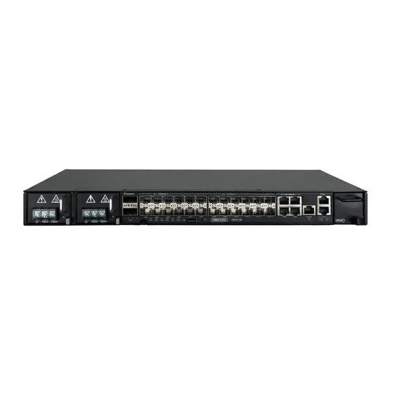
CSR300/AS7315-30X (includes 2 PSUs and 1 fan tray)
2.
Rack Mounting Kit—2 brackets and 8 screws
3.
Grounding kit—grounding lug, 2 screws, and 2 washers
1
2
4
3
1.
2 x DC or AC PSUs
2.
2 x 100G QSFP28 ports
3.
Product tag
4.
8 x 25G SFP28 ports
5.
USB storage port
6.
Reset button
1
2
1.
QSFP28 Port LEDs:
Blue — 100G
Green — 40G
2.
QSFP28 Breakout LEDs:
White — 2 x 50G
Blue — 4 x 25G
Green — 4 x 10G
FRU Replacement
PSU Replacement
1.
Remove the power cord.
2.
Press the release latch and
remove the PSU.
3.
Install replacement PSU.
PSU
Replacement
*150200002459A_R01*
Package Contents
1
10
7
8
6
5
9
3
6
3.
SFP28 Port LEDs: Blue (25G),
Green (10G), Cyan (1G)
4.
SFP+ Port LEDs: Green (10G),
Amber (1G)
5.
1G RJ-45 Port LEDs:
Left (link), Right (activity)
Fan Tray Replacement
Fan Tray
1.
Press the fan tray's release
Replacement
latch.
1.
Press the
2.
Pull out to remove the tray.
release latch
in the fan tray
3.
Install replacement tray with
handle.
matching airflow direction.
2
3
4.
Ring lugs (x4) (included with DC PSUs only)
5.
(Optional) AC power cord
6.
Documentation—Quick Start Guide (this document) and Safety
and Regulatory Information
Overview
11
7.
16 x 10G SFP+ ports
8.
4 x 1G RJ-45 ports
9.
PPS/ToD RJ-45 timing port
10.
Management I/O: 1000BASE-T RJ-45, RJ-45 console
11.
Fan tray
12.
Grounding screw
Status LEDs
4
6.
System LEDs:
LOC — Blinking Blue (OK)
DIAG — Green (OK), Orange (fault detected)
PSU1/2 — Green (OK), Orange (fault)
FAN — Green (OK), Orange (fault)
ALRM — Green (OK), Red (alarm)
7.
PPS/ToD LED: Blinking Green (1PPS input)
8.
RJ-45 Management Port LEDs: Left (link), Right (activity)
1. Left-to-Right Airflow
Remove the left-to-right airflow
fan tray (indicated by the arrow
on the panel).
PSU
Replacement
– 1 –
www.edge-core.com
4
5
5
5
7
8
Airflow Reversal
2. Right-to-Left Airflow
Install a right-to-left airflow fan tray
(indicated by the arrow on the
panel).
6
12
Fan Tray
Replacement
1.
Press the
release latch
in the fan tray
handle.
E112021-CS-R01
150200002459A
Advertisement

Related Manuals for Edge-Core CSR300/AS7315-30X


Summary of Contents for Edge-Core CSR300/AS7315-30X
- Page 1 Cell Site Gateway www.edge-core.com CSR300/AS7315-30X Package Contents CSR300/AS7315-30X (includes 2 PSUs and 1 fan tray) Ring lugs (x4) (included with DC PSUs only) Rack Mounting Kit—2 brackets and 8 screws (Optional) AC power cord Grounding kit—grounding lug, 2 screws, and 2 washers Documentation—Quick Start Guide (this document) and Safety...
- Page 2 (ONIE) software installer preloaded, but no router software surface treatment). image. Information about compatible router software can be Attach Grounding Wire found at www.edge-core.com Attach the grounding wire (#6 AWG/16 mm ) to the grounding point on Note: The drawings in this document are for illustration only the router’s rear panel or side panel.
- Page 3 Quick Start Guide The following transceivers are supported in the SFP28 ports: Caution: Before connecting power supply cables to the router, 25GBASE-SR ■ ensure that power to the feed lines is turned off at the supply 25GBASE-LR ■ circuit breaker or disconnected from the power bus. Attention: Avant de connecter les câbles d’alimentation au The following transceivers are supported in the SFP+ ports:...
- Page 4 Quick Start Guide Hardware Specifications Router Chassis Size (WxDxH) 440 x 300 x 44 mm (17.32 x 11.81 x 1.73 in.) Weight 5.35 kg (11.79 lb), with two installed PSUs Temperature Operating: -40° C to 65° C (-40° F to 149° F) Transportation: -40°...
Need help?
Do you have a question about the CSR300/AS7315-30X and is the answer not in the manual?
Questions and answers