Table of Contents
Advertisement
Advertisement
Table of Contents

Related Manuals for Viessmann VITOCLIMA 300-S


Summary of Contents for Viessmann VITOCLIMA 300-S
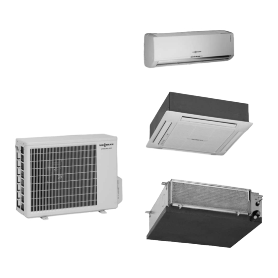
- Page 1 VIESMANN Service instructions for contractors Vitoclima 300-S Single split air-conditioning unit with inverter technology Comprising an external unit and an internal device For applicability, see the last page VITOCLIMA 300-S Please keep safe. 5692 687 GB 8/2008...
- Page 2 Safety instructions Safety instructions Please follow these safety instructions closely to prevent accidents and material losses. Safety instructions explained the Code of Practice of relevant trade associations. Danger all current safety regulations as This symbol warns against the defined by DIN, EN, VDE and all risk of injury.
- Page 3 Replace faulty components compromise its function. Instal- only with original Viessmann ling non-authorised compo- spare parts. nents and non-approved modifications or conversions can compromise safety and may invalidate our warranty.
-
Page 4: Table Of Contents
Index Index Commissioning, inspection, maintenance Steps - commissioning, inspection and maintenance ........Further details regarding the individual steps ..........Troubleshooting Diagnosis ....................15 Refrigerant circuit..................30 Connection and wiring diagrams Internal devices ..................31 External units ..................... 38 Parts lists Parts lists, internal devices ................. -
Page 5: Commissioning, Inspection, Maintenance
Commissioning, inspection, maintenance Steps - commissioning, inspection and maintenance For further information regarding the individual steps, see the page indicated Commissioning steps Inspection steps Maintenance steps Page 1. Switching OFF the unit and the main fuse/MCB ..2. -
Page 6: Commissioning Steps
Commissioning, inspection, maintenance Steps - commissioning, inspection and . . . (cont.) Commissioning steps Inspection steps Maintenance steps Page 21. Charging the external unit with refrigerant (if units/ devices must be separated) .......... -
Page 7: Further Details Regarding The Individual Steps
Commissioning, inspection, maintenance Further details regarding the individual steps Switching OFF the unit and the main fuse/MCB Danger Touching 'live' components can result in the transfer of dangerous body currents. Isolate the unit from the power supply, check that it is no longer 'live' and safeguard against unauthorised reconnection. -
Page 8: Filling The Refrigerant Lines And Internal Device With Refrigerant
Commissioning, inspection, maintenance Further details regarding the individual steps (cont.) B Filling hose for connecting the E External unit pressure gauge set and the F Internal device vacuum pump G Suction line C Pressure gauge set H Liquid line D Filling hose for the suction side K Service valve with protective cap (one hose end with valve) L Three-way valve... - Page 9 Commissioning, inspection, maintenance Further details regarding the individual steps (cont.) 1. Remove protective valve caps C and F from valves A and D of external unit K. 2. Open valve locksB and E with an Allen key. 3. Fit and tighten protective valve caps C and F with 11 to 13 Nm.
-
Page 10: Checking The Refrigerant Lines For Leaks
Commissioning, inspection, maintenance Further details regarding the individual steps (cont.) Checking the refrigerant lines for leaks Danger Check all flanged connections of the Prevent an unregulated escape refrigerant lines between the internal of R 410A in sealed rooms; device and the external unit for refrig- ensure adequate ventilation. -
Page 11: Checking The Condensate Drain Of The Internal Device
Commissioning, inspection, maintenance Further details regarding the individual steps (cont.) A Internal device D External unit B Suction line E Oil lift bends C Liquid line Checking the condensate drain of the internal device Please note Should the water not drain fully Accumulations of condensate through the drain hose of the internal can result in equipment... -
Page 12: Checking The Free Rotation Of The External Fan
Commissioning, inspection, maintenance Further details regarding the individual steps (cont.) Checking the free rotation of the external fan Danger 1. Remove the front grille from the Unintentional starting of the fan external unit. can lead to severe injuries. Isolate the unit from the power 2. -
Page 13: Cleaning The Air Filter Of The Internal Device
Commissioning, inspection, maintenance Further details regarding the individual steps (cont.) Cleaning the air filter of the internal device Note The air filter prevents the ingress of dust and other particles. A blocked air filter can reduce the output of the air-conditioning unit substan- tially. -
Page 14: Switching The Unit On
Commissioning, inspection, maintenance Further details regarding the individual steps (cont.) Switching the unit ON Switch on the unit with the remote See operating instructions. control of the internal device. Checking the system function (output test) Allow the unit to operate in cooling Check the temperature of the inrush- mode for at least 15 min at a high fan ing and blown-out air. - Page 15 Troubleshooting Diagnosis Scanning fault codes in diagnostic mode In diagnostic mode, fault codes can be scanned individually for the internal device and the external unit. For a detailed description of the control and display elements, see the operating instructions for the "Vitoclima-S". Enabling the diagnostic mode: Switching between the diagnosis of the external unit and the diagnosis...
- Page 16 Troubleshooting Diagnosis (cont.) Fault code Fault Cause/Remedy Room temperature Check sensor connection; sensor not connected replace sensor Room temperature sensor short circuit Temperature sensor of the heat exchanger of the internal device not connected Short circuit of the temperature sensor of the heat exchanger of the internal device Suction gas tempera-...
- Page 17 Troubleshooting Diagnosis (cont.) Fault code Fault Cause/Remedy Overtemperature cut- out of the heat exchan- ger of the internal de- vice (N/A) EEPROM not updated Unit operates with ROM parameters; no change of EEPROM faulty the unit settings (fan, tem- perature etc.) possible. Replace the controller of the internal device.
- Page 18 Troubleshooting Diagnosis (cont.) Note Only one fault code will be displayed, even if several faults have occurred. To display further fault codes: Switch the unit OFF and isolate it from the power supply. Remove the fault. Call up the diagnostic function again. Fault code Fault Cause/Remedy...
- Page 19 Troubleshooting Diagnosis (cont.) Fault code Fault Cause/Remedy Processor fault Controller problem, external unit: Check the connecting cable and jumper settings; replace controller EEPROM faulty Device operates with ROM parameters; replace the con- troller of the external unit DC undervoltage Check the voltage at the ex- ternal unit DC overvoltage AC undervoltage...
- Page 20 Troubleshooting Diagnosis (cont.) Fault codes external unit, type OS307H Fault codes are illustrated through the simultaneous illumination of the cooling and heating LEDs. The heating LED illuminates 5 times in succession. Either the cooling LED illu- minates at the same time or not. This results in the fault code detailed in the following table: Note The fault code can also be checked at the LEDs of the external unit.
- Page 21 Troubleshooting Diagnosis (cont.) Fault code Fault Cause/Remedy Processor fault exter- Overheating/overvoltage at nal fan the external fan controller; air inlet blocked; motor jum- per incorrectly placed on the external unit controller; check external fan motor External fan idle Check external fan motor Max.
- Page 22 Troubleshooting Diagnosis (cont.) Fault code Fault Cause/Remedy System configuration Incorrect internal device fault connected; change config- uration Overtemperature cut- Air inlet blocked; check ex- out, processor (com- ternal fan motor pressor is switched OFF) Protection against Enabled during defrosting; icing-up no fault Overtemperature cut- Check whether there is in-...
- Page 23 Troubleshooting Diagnosis (cont.) Fault Possible cause Remedy Limited heating output External temperature below -2 °C, see page 48 The standby LED of the No mains voltage (or too Check power supply internal device does not low) at the PCB term- illuminate inals (internal device) PCB (internal device)
- Page 24 Troubleshooting Diagnosis (cont.) Fault Possible cause Remedy In cooling mode, limited Ice forms at the heat ex- Fix leak; fill system with air delivery and internal changer of the internal refrigerant device whistles device due to a refrig- eration leak No air delivery at the ex- No voltage at the exter- Check the power supply...
- Page 25 Troubleshooting Diagnosis (cont.) Fault Possible cause Remedy Compressor overheated; Electronic expansion Check expansion valve insufficient output; equip- valve faulty and replace, if required ment enters fault state Controller of the external Scan fault code (see and compressor switches unit or refrigerant circuit page 15) OFF without obvious rea- faulty...
- Page 26 Troubleshooting Diagnosis (cont.) Checking the essential components of the external unit, type OS303H, OS304H, OS305H Power supply The mains voltage must be between 198 and 264 V~. External fan Start test mode (see page 29). Across the orange and black core: Check the voltage at the fan motor 15 V ±...
- Page 27 Troubleshooting Diagnosis (cont.) Main fuse/MCB (20 A) If the fuse has blown: Changing fuses. Check the compressor, fan and other If the fuse blows regularly, replace the components that may be able to external unit controller. cause a short circuit. Choke coil Check the connections of the choke Check for a short circuit between the...
-
Page 28: Troubleshooting Diagnosis
Troubleshooting Diagnosis (cont.) In heating mode, check the voltage If there is no voltage, check the elec- across both connections of the rever- tromagnet with a direct power supply. sing valve. The standard voltage is If OK, replace the external unit con- 230 V~. - Page 29 Troubleshooting Diagnosis (cont.) Never route the air-conditioning Use suppression filters. system cables together with aerial Use signal amplifiers. cables. Use aerial cables with a good screen. Activating test mode The test mode enables the checking of the air-conditioning unit with fixed para- meters.
-
Page 30: Refrigerant Circuit
Refrigerant circuit Refrigerant circuit A Heat exchanger of the external E Heat exchanger of the internal unit with temperature sensor device with temperature sensor B Four-way reversing valve F Valve with connection for liquid C Compressor line D Three-way valve with connection G Filter for suction line and service valve H Electronic expansion valve... - Page 31 Connection and wiring diagrams Internal devices Wall mounted devices, type W303H and W304H A Connection with external unit F Ioniser B Control PCB G Electrostatic filter C Fan H Stepper motor for air flaps D Room temperature sensor K On-site time switch (option) E Temperature sensor at the heat L Display PCB exchanger of the internal device...
-
Page 32: Connection And Wiring Diagrams Internal Devices
Connection and wiring diagrams Internal devices (cont.) Wall mounted device, type W305H A Connection with external unit G Ioniser B Display PCB H Electrostatic filter C Control PCB K Stepper motor for air flap D Fan L Stepper motor for air flap E Room temperature sensor M On-site time switch (option) F Temperature sensor at the heat... - Page 33 Connection and wiring diagrams Internal devices (cont.) Cassette devices, type C303H, C304H and C305H A Connection with external unit F Display PCB B Room temperature sensor G Stepper motor for vertical air flap C Temperature sensor at the heat H Condensate overflow switch exchanger of the internal device K Fan D Power supply, 230 V~, 50 Hz...
- Page 34 Connection and wiring diagrams Internal devices (cont.) M Stepper motor for horizontal air O Interface RS485 flap P On-site time switch (option) N Condensate pump Colour coding to DIN IEC 60757 Black GNYE Green/Yellow Brown Grey Blue...
- Page 35 Connection and wiring diagrams Internal devices (cont.) Duct mounted device, type D304H A Connection with external unit F Receiver B Room temperature sensor G Condensate overflow switch C Temperature sensor at the heat H Fan exchanger of the internal device K Stepper motor for horizontal air D Power supply, 230 V~, 50 Hz flap...
- Page 36 Connection and wiring diagrams Internal devices (cont.) M Interface RS485 N On-site time switch (option) Colour coding to DIN IEC 60757 Black Grey Brown Blue White GNYE Green/Yellow Duct mounted device, type D305H A Ioniser (option) E Condensate overflow switch B Fuse, T3, 15 A, slow F Room temperature sensor C On-site condensate pump (option)
- Page 37 Connection and wiring diagrams Internal devices (cont.) H MegaTool (not available) M Power supply, 230 V~, 50 Hz K Connection with external unit N Fan L Remote control receiver with LEDs and user interface Colour coding to DIN IEC 60757 Black First floor Orange Brown...
-
Page 38: External Units
Connection and wiring diagrams Internal devices (cont.) C On-site condensate pump (option) H MegaTool (not available) D On-site time switch (option) K Connection with external unit E Condensate overflow switch L Remote control receiver with F Room temperature sensor LEDs and user interface G Temperature sensor at the heat M Fan exchanger of the internal device... - Page 39 Connection and wiring diagrams External units (cont.) A Control PCB K Compressor temperature sensor B Compressor L Suction gas temperature sensor C Choke coil M MegaTool connection (not avail- D Four-way reversing valve able) E Defrost heater, 230 V~ (option) N Electronic expansion valve F Fan O Connection with internal device...
- Page 40 Connection and wiring diagrams External units (cont.) Type OS307H A Control PCB B Power supply PCB...
- Page 41 Connection and wiring diagrams External units (cont.) C EMI filter PCB P Compressor temperature sensor D Terminals R Outside temperature sensor E Defrost heater, 230 V~ (option) S Accessory connections F Four-way reversing valve 1 Night mode switch G Fan voltage 2 Standby switch H Compressor 3 Economy switch...
-
Page 42: Parts Lists
Parts lists Parts lists, internal devices Wall mounted devices, type W303H, W304H and W305H When ordering spare parts: 007 Fan motor Quote the part and serial no. (see 008 Stepper motor for air flaps type plate) and the item no. of the 009 Display PCB required part (as per this parts list). -
Page 43: Parts List, External Units
Parts lists Parts lists, internal devices (cont.) Duct mounted devices, type D304H, D305H and D307H When ordering spare parts: 018 Control PCB Quote the part and serial no. (see 020 Room temperature sensor (only type plate) and the item no. of the type D304H) required part (as per this parts list). -
Page 44: Commissioning/Service Reports
Commissioning/service reports Maintenance checklist Vitoclima 200-S/300-S Assembly checke- Cleane- Comments placed Internal device Heat exchanger sur- face Fins Condensate pan Air filter Air temperatures [ °C] Inlet Outlet External unit Fins Heat exchanger sur- face Condensate drain Air temperatures [ °C] Inlet Outlet Compressor in the external unit... - Page 45 Commissioning/service reports Maintenance checklist Vitoclima 200-S/300-S (cont.) Assembly checke- Cleane- Comments placed Control unit and electrical equipment Contactors Remote control Cables Temperature sensors Relay Other Tested by: Date:...
- Page 46 Specification Specification Output overview Equip- Output in kW Power consumption Energy efficiency ment in kW Cooling Heating Cooling Heating Cooling Heating (EER) (COP) W303H 0.81 4.2 (A) 4.2 (A) with (1.4 - 3.6) (1.5 - 5) (0.4 - 1.0) (0.4 - 1.6) OS303H W304H 3.5 (A)
- Page 47 Specification Specification (cont.) Power supply Operating voltage: 230 V / 50 Hz Equipment Rated current in A Starting cur- Fuse (slow) rating Cooling Heating rent in A in A W303H with 10.5 OS303H W304H with OS304H W305H with OS305H C303H with OS303H C304H with OS304H...
-
Page 48: Specification Specification
Specification Specification (cont.) Lead Cable cross-section length a + b 1.5 mm 1.5 mm 20 m a + b > 2.5 mm 2.5 mm 20 m Power connection on the external unit Type D307H A Power supply cable C Internal device B Connecting cable D External unit Lead... -
Page 49: Specification, Internal Devices
Specification Specification, internal devices Wall mounted boilers Internal device W303H W304H W305H External unit OS303H OS304H OS305H 1 crosscurrent fan 1 radial fan Speed (3 stages) 1200/1050/ Air flow rate cooling 530/430/330 550/450/350 850/760/620 (3 stages) Air flow rate heating 570/460/350 580/480/370 850/760/620... - Page 50 Specification Specification, internal devices (cont.) Internal device C303H C304H C305H External unit OS303H OS304H OS305H Dimensions Width Height Length Weight Condensate drain pipe " (internal Ø) Duct mounted devices Internal device D304H D305H D307H External unit OS304H OS305H OS307H 2 radial fan 1 radial fan Speed (3 stages) rpm 1150/1000/...
-
Page 51: Specification External Units
Specification Specification external units External unit type OS303H OS304H OS305H OS307H Refrigerant R410A Refrigerant control Electronic expansion valve Compressor Rotating piston Scroll Double piston Fans 1 axial fan Speed Air volume 1780 1780 2160 3600 Sound power level dB(A) dB(A) Sound pressure level Dimensions Width... -
Page 52: Certificates
Certificates Declaration of conformity We, Viessmann Werke GmbH & Co KG, D-35107 Allendorf, confirm as sole responsible body that the product Vitoclima 300-S complies with the following standards: EN 255 EN 55 082-1 EN 378 EN 60 204-1 EN 55 014-1; 2003-09 EN 60 335-1;... -
Page 53: Keyword Index
Keyword index Keyword index Active charcoal filter Electromagnetic faults ........Applicability Electrostatic filter . - Page 56 Applicability Applicable for air-conditioning units Vitoclima 300-S: Internal devices Type from serial no. W303H 3004 481 W304H 3004 482 W305H 3004 483 C303H 3004 484 C304H 3004 485 C305H 3004 486 D304H 3004 487 D305H 3004 488 D307H 3004 499...
Need help?
Do you have a question about the VITOCLIMA 300-S and is the answer not in the manual?
Questions and answers