
Related Manuals for Ibml ImageTrac 6000 Series

Summary of Contents for Ibml ImageTrac 6000 Series
- Page 1 Version 1.3.1 ImageTrac Install Guide for Series 6000 Scanners Information capture. Done right.™...
-
Page 2: How To Use This Manual
ImageTrac where you are not instructed to do so. Refer servicing to The Call ibml Customer Support icon indicates where you qualified personnel only. should call for information such as part numbers or for additional assistance. -
Page 3: Operator Instructions
Note: For pluggable equipment, the impaired due to illness, stress, or if you are under the influence socket-outlet shall be installed near the of medication, alcohol, or other drugs. equipment and shall be easily accessible. Information capture. Done right 866-798-4265 www.ibml.com ™... -
Page 4: Section 1: Introduction
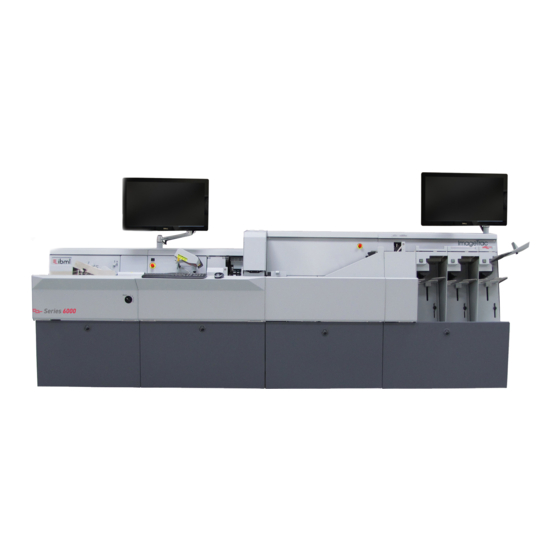
Information capture. Done right 866-798-4265 www.ibml.com ™ Section 1: Introduction Welcome to the ImageTrac Series 6 Installation Manual. This information Power Connection Required guides you through the process of unpacking and installing the US Sites - Units shipped with power cord and 208-240 V, Nema #L6-30 ImageTrac Scanner. - Page 5 (74.93 cm) (89.2048 cm) (84.4 cm) 97.85 inches (244.539 cm) 106.769 inches (271.193 cm) With Run-Out Note: The ventilation and maintenance area at the rear of the ImageTrac is essential for safe continuous operation. Information capture. Done right 866-798-4265 www.ibml.com ™...
- Page 6 Information capture. Done right 866-798-4265 www.ibml.com ™ ImageTrac Scanner Series 6: 6400 Class Multiple Pocket Scanner Ventilation and Maintenance Area Decision Feeder Transport Pocket Escalator 36 inches 29.5 inches 35.12 inches 33.23inches 36 inches (91 cm) (75 cm) (89 cm) (84.4 cm)
- Page 7 Because of this, each frame will need to be gently lowered to the floor as it exits the crate. 3. Remove all packing materials from around the frame. The frame may now be placed in position on the floor. Information capture. Done right 866-798-4265 www.ibml.com ™...
- Page 8 Information capture. Done right 866-798-4265 www.ibml.com ™ Crated Feeder Frame shown with front panel removed. Be aware of a drop of approximately 3 inches (7.62cm) from the bottom of the crate to the floor. Exercise extreme caution not to let the ImageTrac drop, and keep all body parts clear during unpacking.
- Page 9 ImageTrac. The contents of this box should be stored in close proximity to the ImageTrac at all times for service purposes. Information capture. Done right 866-798-4265 www.ibml.com ™...
- Page 10 Information capture. Done right 866-798-4265 www.ibml.com ™ 5. Once the system is unpacked, remove the front frame covers by pulling the black latch on each cover to release the top of the cover. For each frame, pull the cover forward and lift it off. Set the covers off to the side until the installation is complete.
- Page 11 Important: The Rear Camera Frame uses a pair of nuts (ibml part number 008-00073) to attach the upper front bracket. It is important to attach this bracket to the Rear Camera Frame before any others.
- Page 12 Information capture. Done right 866-798-4265 www.ibml.com ™ 2. Repeat step 1 for each frame. Brace placement on the front of the ImageTrac. Notice that the upper braces are recessed .
- Page 13 Scanners that have 4 frames or more have two stabilizing braces. These braces overlap to provide added stability across multiple frames. Overlapping stabilizing brace on four or more frame scanners. Information capture. Done right 866-798-4265 www.ibml.com ™...
- Page 14 Information capture. Done right 866-798-4265 www.ibml.com ™ Scanners that have four or more frames need extra screws installed to 3. After all connections have been made, secure the ImageTrac in place ensure stability of the scanner. by locking the back wheel brake. This can be done by pressing the...
- Page 15 Grounding straps must be tightened with a wrench for safe and efficient operation of the ImageTrac. Use a 7mm socket driver or adjustable wrench to secure grounding straps between frame bases. Information capture. Done right 866-798-4265 www.ibml.com ™...
-
Page 16: Power Connections
Information capture. Done right 866-798-4265 www.ibml.com ™ B. Power The following steps address the necessary power connections. All frames must be connected correctly for proper functionality. All connections should be made with wires crossing inside each frame, ensuring that no cables are crimped or pinched between frames. - Page 17 Pass the ends through the frames and plug an end into the green connections on the DC Secondary Master Power Supplies in the Registration frame and the DC Secondary Add-On Power Supply in the multi-pocket frames. Information capture. Done right 866-798-4265 www.ibml.com ™...
- Page 18 Information capture. Done right 866-798-4265 www.ibml.com ™ Power System Locations in the Registration Frame DC Distribution Board DC Secondary Master AC Inlet AC Primary...
- Page 19 TB2 +24V DC NO C (CABLE) MODULE CONT. POWER REAR CAMERA TB2 +24V RETURN NO C (CABLE) MODULE CONT. POWER FRONT CAMERA +28V DC +28V DC RETURN GND SIGNAL DC Distribusion on the Registration Frame Information capture. Done right 866-798-4265 www.ibml.com ™...
- Page 20 Information capture. Done right 866-798-4265 www.ibml.com ™ FRONT VIEW CONN NAME WIRE COLOR SIGNAL NAME/CABLE # (CABLE) +28V DC PWR FOR 150-00147 IJP BOARD (CABLE) +28V RETURN PWR FOR 150-00147 IJP BOARD BLACK GND SIGNAL NEXT DISTRUBUTION PCB - E3...
- Page 21 110-00682 THE INFORMATION DISCLOSED BY IMAGING BUSINESS MACHINES, LLC THIS DOCUMENT IS CONFIDENTIAL Information capture. Done right 866-798-4265 www.ibml.com ™ AND ITS USE IS RESTRICTED BY THE PROPRIETARY RIGHTS E-STOP WIRING DIAGRAM CLAIMED BY IMAGING BUISNESS DC SECONDARY MASTER/DC SECONDARY ADD-ON...
- Page 22 Information capture. Done right 866-798-4265 www.ibml.com ™ Data/Communication The following steps address the necessary data connections. All frames must be connected correctly for proper functionality. All connections should be made with wires crossing inside each frame, ensuring that no cables are crimped or pinched between frames.
-
Page 23: Camera Cables
Ensure that the camera data cables are connected at both ends for front and rear cameras. For ease of connection, the camera cables are now color coded. The Front Camera has a yellow zip tie. The Rear Camera has a red zip tie. Information capture. Done right 866-798-4265 www.ibml.com ™... - Page 24 Information capture. Done right 866-798-4265 www.ibml.com ™ Any time the cables connected to the rear of a camera are removed or installed, first remove the ferrite assemblies from the cables; then clip them on after all screws have been secured.
- Page 25 When removing the cable do not remove the top screw completely and then the bottom screw. Use the same alternating pattern and while holding the cable into the connector remove the top screw last. Note: To prevent over tightening or stripping the thumbscrews, it is important to avoid using a screwdriver on the thumbscrews. Information capture. Done right 866-798-4265 www.ibml.com ™...
- Page 26 Information capture. Done right 866-798-4265 www.ibml.com ™ Section 6: Embedded Application Controller Connections and Cabling This section shows the connections on the Embedded Application Controller and which cables are attached to each connection. All cables must be connected to ensure proper functioning of the ImageTrac Series 6.
-
Page 27: Cable Management System
From the rear of the ImageTrac, attach the cable management system to the Embedded Application Controller rack mount. There are some small differences between the cable management for the 180-00026/180-00027 and 180-00030 but these differences are largely cosmetic. Information capture. Done right 866-798-4265 www.ibml.com ™... - Page 28 Information capture. Done right 866-798-4265 www.ibml.com ™ The Cable Management System for the Embedded Application Controller attaches to a latch that secures the system in place. The Cable Management System sits on a platform to support the Cable Management System and keep it in place.
-
Page 29: Power Cables
The power cables are located in the Transport Frame and are attached to the Main Power Supply. They are also attached to the Embedded Application Controller in the Feeder Frame. Embedded Application Controller 180-00026 US/EU or 180-00027 China and 180-00030 Information capture. Done right 866-798-4265 www.ibml.com ™... - Page 30 Information capture. Done right 866-798-4265 www.ibml.com ™ Camera Cables Attach the data cables for the front and rear cameras to the camera boards in the Embedded Application Controller. The camera cables are color coded with Red and Yellow zip ties to ensure that the cables are attached to the correct camera. In most instances, the yellow coded camera link cable will be plugged in closest to the rear of the scanner.
-
Page 31: Network Cables
Embedded Application Controller (180-00030) Connect the green Cat 5 ethernet cable to the on board NIC labeled 2 for the Realtime Transport Controller. Embedded Application Controller (180-00026 US/EU or 180-00027 China) Embedded Application Controller (180-00030) Information capture. Done right 866-798-4265 www.ibml.com ™... - Page 32 Information capture. Done right 866-798-4265 www.ibml.com ™ Connecting the Monitor to the Embedded Application Controller Connect the white USB cable to any USB port. This attaches to the Monitor Touch Screen. The video cable connects to the on board video.
-
Page 33: Section 7: Attaching The Monitor
The monitor is located in the monitor box which is found in the over pack box. Carefully remove the monitor from it’s box and attach to the armature monitor mount. M4 x 10mm Information capture. Done right 866-798-4265 www.ibml.com ™... - Page 34 Information capture. Done right 866-798-4265 www.ibml.com ™ Connect the power, DisplayPort and USB to the connections on the back of the monitor. DisplayPort Power...
- Page 35 CAUTION: DO NOT overtighten fasteners. Overtightening may cause damage to your equipment. CAUTION: DO NOT overtighten fasteners. Overtightening may cause damage to your equipment. CAUTION: DO NOT remove screw. Removing screw may cause damage to equipment. Information capture. Done right 866-798-4265 www.ibml.com ™...
-
Page 36: Main Power Supply
Information capture. Done right 866-798-4265 www.ibml.com ™ Section Eight: Powering on the ImageTrac Before attempting the following power on procedure, please ensure that all connections, hardware and electrical, are secure. Any networking to external systems must also be completed. After completing installation connections, power may be connected. - Page 37 2. Place the main breaker switch in the “on” position. This breaker controls all incoming AC power to the ImageTrac. It is located on the back of the Main Base Power Supply. Information capture. Done right 866-798-4265 www.ibml.com ™...
- Page 38 Information capture. Done right 866-798-4265 www.ibml.com ™ 3. Place the Embedded Application Controller/Monitor breaker switch in the “on” position. It is located on the back of the Main Base Power Supply and is shown in red and green. This breaker controls all incoming AC power to the touchscreen monitor and to the two power supplies in the Embedded Application Controller.
- Page 39 Registration Module. Once the Transport PC initializes, AC power is then provided to the remainder of the ImageTrac control logic. In the “Off” position, AC power may still be supplied to the Embedded Application Controller. You must disconnect the scanner’s AC power supply before servicing. Information capture. Done right 866-798-4265 www.ibml.com ™...
-
Page 40: Emergency Stop Switches
Information capture. Done right 866-798-4265 www.ibml.com ™ Emergency Stop Switches The emergency stop switches are also located on the front of the ImageTrac. Using either of these switches immediately shuts down power to the 28 volt transport motors. This action stops the movement of the track only. The Emergency Stop Switch should be used only for emergencies. -
Page 41: Power On Checklist
ImageTrac. q Engage the operator switch to power on the Transport PC and the scanner. This switch is located above the Emergency Stop Switch on the Registration module. Information capture. Done right 866-798-4265 www.ibml.com ™... - Page 42 Information capture. Done right 866-798-4265 www.ibml.com ™ Section Nine: PC, Monitor, and Over Pack Box Components not shipped on the frames will ship in the PC box, including the monitor which is in the original monitor box. There are also several attachments included in an over pack box shipped with the ImageTrac.
-
Page 43: Additional Items
There will also be additional items in the over pack box. While the contents of this box will remain somewhat consistent there may be changes specific to a particular customer’s needs. Over Pack Items ibml Part Number Quantity 4mm w/6” T-handle Hex wrench, 008-00275 1/16”... - Page 44 Information capture. Done right 866-798-4265 www.ibml.com ™ Apendix A: ImageTrac Series 6 System Wiring Diagram REVISIONS DESCRIPTION DATE DIO_Rear_Camera Page 2 RELEASED 03/26/2014 To External Server Rear Illumination CameraLink Camera Controller MOD BACKPLANE "FROM" PORT NAME "TO" Illum RGB LED...
- Page 45 MACHINES LLC. Module TOLERANCES: 1/16" UNLESS SIZE DATE DWG NO Variable Fan Cntlr. OTHERWISE NOTED 03/26/2014 IT6_SYS_WIRING DRAWN BY: J. Johnson SHEET SCALE not to scale 2 OF 2 ImageTrac_S6_System_Diagram 03/26/2014 11:51:04 AM Information capture. Done right 866-798-4265 www.ibml.com ™...
- Page 46 Information capture. Done right 866-798-4265 www.ibml.com ™ Notes:...
- Page 47 Notes: Information capture. Done right 866-798-4265 www.ibml.com ™...
- Page 48 866-798-4265 www.ibml.com ™ For Questions Regarding the ImageTrac Scanners Please Contact: ibml Customer Support 1-866-798-4265 support@ibml.com ©2014 Imaging Business Machines, LLC. All rights reserved. Imaging Business Machines, LLC may have patents, patent applications, trademarks, copyrights, or other intellectual property rights covering subject matter in this document. Except as expressly provided in any written license agreement from Imaging Business Machines, the furnishing of this document does not give the user any license to these patents, trademarks, copyrights, or other intellectual property.
Need help?
Do you have a question about the ImageTrac 6000 Series and is the answer not in the manual?
Questions and answers