Table of Contents

Related Manuals for MERRICK MC3


Summary of Contents for MERRICK MC3
- Page 1 R:\MANUALS\ENGLISH\MC3\2496ex_g\2496_G1.doc 08/14/01 3:57 PM/LDD MC³ Controller Operation and Maintenance Manual for the 24.96.EX.G Belt Feeder Merrick Industries, Inc. 10 Arthur Drive Lynn Haven, FL 32444 (850) 265-3611 Revisions...
- Page 2 The information in this manual, including technical data and copies of drawings, embodies information proprietary to Merrick Industries, Incorporated. This manual is provided to the user of equipment purchased from Merrick Industries, Inc. for use only in operation or maintenance of such equipment.
-
Page 3: Table Of Contents
INTRODUCTION ............................1 SAFETY..............................1 In General..............................1 Electrical Precautions..........................1 MANUAL CONVENTIONS ........................1 Buttons ..............................1 Screens ..............................2 SOLVING PROBLEMS ..........................2 Help Button............................2 Technical Support ..........................2 SYSTEM CONCEPTS ...........................3 HARDWARE .............................3 Enclosure ..............................3 Backplane Board ..........................4 Card Stack Assembly..........................4 CPU Board............................4 PCAD Board .............................4 PCIO Board ............................4 LTI Board ............................4 Power Supply Assembly........................4... - Page 4 Setpoint ...............................11 LOGO..............................11 Start, Stop, Clear Batch........................11 Indicators ( on Feeder Screen) ......................11 General Alarms ...........................12 Belt Load Over Limit ........................13 Belt Load Under Limit ........................13 PCAD Near Zero..........................13 PCAD Near Full ..........................13 Z Track Out Of Range ........................13 PCAD Discrepancy .........................13 Tachos Do Not Comply........................13 Communications Lost ........................13 Setpoint Out Of Range ........................13...
- Page 5 List of Unit String Combinations .....................24 Decimal Points ............................25 Design Capacities ..........................25 PID Parameters & Output Dynamic Protection ...................25 Gain ..............................26 Integral ............................26 Derivative ............................26 SCR Accel %/s and SCR Decel %/s....................26 Start Speed .............................26 Limit Switches .............................26 FeedRate HI/LO..........................27 Feedrate Rel Dev..........................27 Feedrate Setpoint Deviation ......................27 Numeric Parameters........................27...
- Page 6 FRC (button) / FC (indication)......................37 List of Logical Inputs ........................37 List of Physical Inputs ........................38 Default Input Mapping........................39 Digital Outputs ..........................40 INV (button) / RV (indication) ......................40 FRC (button) / FC (indication)......................40 TAB..............................40 List of Logical Outputs ........................41 List of Physical Outputs ........................42 List of Default Output Settings ......................43 Sample Rate ............................43 Internal Sample Rate Parameters ....................43...
- Page 7 PCAD1 and PCAD2 ........................58 LL ..............................58 Abs..............................58 Cnts ..............................59 Z Ld..............................59 Settings ............................59 Scale Factor............................59 Communication Diagnostics........................59 Rx Buffer............................59 Tx Buffer ............................59 Error Counters ..........................59 IIR - ..............................60 LSR -...............................60 TX - ..............................60 RX -..............................61 Communication Parameters ......................61 Tacho Diagnostics..........................61 EMT PULS............................61 PT ..............................61 TST ..............................61...
- Page 8 PCAD BOARD............................70 KEYBOARD LOCATION CODES ......................70 PRINTER PORT............................70 STORAGE ..............................71 STORAGE ON RECEIPT FROM FACTORY..................71 Storage Longer than 6 Months......................71 Storage up to 6 Months ........................71 STORAGE FOLLOWING USE........................71 OPERATION AFTER STORAGE......................71 SPARE PART LIST .............................72 MC³ CONTROLLER SPARE PARTS LIST .....................72 ACCESSORIES FOR THE MC³...
-
Page 9: Introduction
INTRODUCTION SAFETY The Merrick MC³ Controller is used for the monitoring and control of process weighing equipment. To insure personnel safety please read the following instructions and precautions carefully. In General Observe all standard precautions that pertain to moving machinery. -
Page 10: Screens
After normal hours and on holidays and week-ends, technical assistance is available by calling 1- 888 MERRICK extension 7878. Follow the instructions and be sure to enter the area code and the phone extension where you can be reached. Someone will return your call as soon as possible. -
Page 11: System Concepts
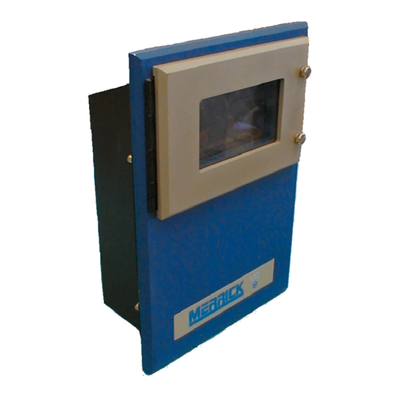
The MC³ Controller has been designed to control many different types of feeding, weighing and metering equipment. This allows for easier maintenance and simplified training. The Standard Merrick MC³ 24.96.EX Controller consists of an Enclosure, an LCD Display, Card Stack and a Power Supply. -
Page 12: Backplane Board
MC³ Controller to communicate with other serial devices such as a SuperBridge or Personal Computer. For more information on MC³ Serial Communications see [1] This specification lists some hardware options and interconnection examples and also describes the Merrick Communications Protocol in detail. -
Page 13: Display Assembly
The Register Database is a set of variables used in the software application. It is provided to allow structured access through Serial Communications to variables used in the MC³. A numeric listing of registers for each application is available from Merrick. Procedures for using Serial Communications to access the register list are also provided in [1]. -
Page 14: Getting Started
Please refer to your wiring diagrams to insure proper installation of the controller. If you need to change the wiring from the supplied wiring diagrams, Merrick must first be consulted to insure safe and proper operation of the controller. See Technical Support on page 2 for contacting the Merrick Technical Service department. -
Page 15: Password Protection
Check all your wiring. At least the load cell(s) and power have to be connected for the controller to work. Normally, a connection diagram is supplied. Read more about inputs and outputs in the “Working With INPUTS AND OUTPUTS” on page 68. Power up your controller. -
Page 16: Graph Screen
Feeder Screen Graph Screen A Graph screen is available to show trend information. This screen also displays the current running status of the controller. Graph Screen MC³ 24.96.EX O&M Manual Page 8 08/14/01 4:34 PM/LDD... -
Page 17: Numerical Display
Numerical Display A large font screen is also available to display the current running status of the controller in a larger typeface for easier viewing from a distance. Numerical Display There are several common elements to the screens which are described below. ENTERING NEW VALUES Numeric Entry Screen Numeric Screen Example... -
Page 18: Sub Menus
Sub Menus button allows access to the setup menu system which includes the EZ Setup functions and the Custom Setup menus (see Setting UP Your Controller on page 21 for more information). button (page 18) allows access to the calibration, total and subtotal reset and diagnostic menus. -
Page 19: Blank Button
See Setpoint on page 15 for more information. LOGO This screen displays the address and phone number for Merrick. It also shows the revision and build date for the software that is currently in operation. The version and build date are important when you need service on your controller. -
Page 20: General Alarms
Switches (page 26). GOOD Good. This indicator is on when all of the following conditions have been met. If any one of the conditions are not met this indicator will not activate. The setpoint method is not Manual Speed. The Feeder Block input is OFF (see Digital Inputs Setup on page 36). The Run Permission input is ON (see Digital Inputs Setup on page 36). -
Page 21: Belt Load Over Limit
Communications Lost This error message indicates that no communications message has been received for a time period exceeding the maximum time allowed. See the Merrick communications Specification Manual for a complete explanation of this error. Setpoint Out Of Range If the feedrate setpoint is less than zero or is greater than the design feedrate this alarm will occur. -
Page 22: No Speed Detected
No Speed Detected This error occurs when the controller expects a belt speed and none exists after 10 seconds. Anain Out Of Range This alarm will occur if the allowed range for the analog inputs have been exceeded. LCD Not Responding This error message indicates that an error occurred while the CPU was testing the status of the LCD Display. -
Page 23: Setpoint
SETPOINT Various screens may be displayed based on the mode of your controller. Setpoint Screens These are the screens you will see when batching and PID logical inputs are turned on. You are able to toggle between the two screens by touching the buttons. -
Page 24: Feedrate
Maximum Error - this value is the maximum error allowed before the batch error logical output is enabled. Maximum Time - The maximum allowed time for a batch process to occur before the logical output “Batch Error” goes on. See List of Logical Outputs (page 41). Preact - is used to turn off the output to the discharge gate ahead of time, allowing the batch setpoint to be reached with a minimum of error. -
Page 25: Local
current depending on jumper setting on the PCIO board (see Analog Outputs on page 70 for more information). Local When this mode is selected, a Feedrate setpoint can be entered by the operator. This setpoint is in engineering units for rate. This mode allows the operator entered setpoint to be used by the controller in conjunction with the current feedrate to develop closed- loop control of the feeder. -
Page 26: Fallback Setpoint
Fallback Setpoint This screen will be displayed when the Logical input Serial Setpoint is enabled and there is a communications failure. This will allow you to set a feedrate value which to default to in the case of communication failure. This setpoint will be enabled after the communications time out has occurred. -
Page 27: Sub-Total
Sub-Total This button clears the Sub-Total and any remaining pulses for the external counter. Clean Screen If the touch screen gets smeared or very dirty it may be necessary to clean the screen. This function gives you 60 seconds to clean the screen without affecting the controller. Diagnostics This selection takes you to the Diagnostic menu. -
Page 28: Pf Buttons
These allow you to move character by character in the selected print string. Touching these buttons will allow you to rotate through the character selection screens. This is the shift button. This allows you to select uppercase or non-alphanumeric characters on the buttons. If a button has two lines displayed the upper set is selected by pressing this button (SHIFT will appear under the string) then pressing the appropriate button. -
Page 29: Setting Up Your Controller
SETTING UP YOUR CONTROLLER SETUP Pressing the button on the Main screen or Large Font screen will display a Password Entry screen (if password is enabled), and once the proper password is entered, the Setup screen will be displayed. See PASSWORD PROTECTION on page 7. There are three selections from the Setup menu. -
Page 30: Weight Ez Setup
Five seconds are allotted to allow the belt to start to spin up for the tacho type and direction detection. Next the speed calibration procedure is performed. This procedure determines the number of tacho pulses per belt revolution. NOTE: The belt must cycle the number of revolutions that is indicated on the speed calibration screen. Touch when you are ready for the test to be performed. -
Page 31: Custom Setup
Entering New Values on page 9 for the proper method to enter values into Numeric Entry Screens. When complete, touch to exit the numeric entry screen and return to EZ Setup procedure. The next series of tests will determine the type and mode of the Tacho attached, the number of pulses per revolution of the belt and the design speed of the feeder. -
Page 32: Setup Screen 1
SETUP SCREEN 1 Setup Screen 1 Units Select To enter the Units Select Menu, press the button from the Setup Screen 1. Use the Up or Down arrow buttons to scroll through the list of units until the combination appears in the center box that is correct for your application. -
Page 33: Decimal Points
PID controller. Several of these methods require little knowledge about the actual dynamics of the system to be tuned. If possible, Merrick will tune the PID controller before the feeder is shipped to you. Otherwise, we recommend you use whatever tuning method you are most familiar with. -
Page 34: Gain
Gain This is the amount of gain associated with the PID algorithm. In the MC³, gain is expressed as a percentage. The higher the gain, the more aggressive controller behavior. A purely proportional controller (with no integral and derivative action) would result in constant error. Too much gain can cause the controller to go unstable. -
Page 35: Feedrate Hi/Lo
The feedrate Logical Output alarms are delayed by settable time parameters, “High Delay” and “Low Delay” to prevent frequent cycling. In addition, there is a “Startup Delay” that is active when the feeder is starting up, from either a blocked state or a zero setpoint. The Main Screen displays are not delayed. -
Page 36: Belt Parameters
Parameter Default High Delay 10 seconds 3600 seconds (1 hour) Low Delay 10 seconds 3600 seconds (1 hour) Startup Delay 0 seconds 3600 seconds (1 hour) Overload Limit Design Load 150% of Design Load Underload Limit - 10% of Design - Design Design Load Load... -
Page 37: Wait Time
The following are the four types of tachometers that can be used with the MC³: Optical 5 Volt digital encoder, either signal channel or quadrature. Mag/F-25 Merrick F-25 Encoder or a 2 wire current loop magnetic style encoder. MC³ 24.96.EX O&M Manual Page 29 08/14/01 4:34 PM/LDD... -
Page 38: Mode
Stepper Brushless pulse generator. Frequency Frequency generator. Mode Mode determines if direction detection is to be utilized. For direction detection, a quadrature encoder must be connected to the MC³, channel A and/or B. A quadrature encoder allows the MC³ to determine when the belt is moving and will only generate a speed signal if the belt is moving in a forward direction. -
Page 39: Numeric Parameters
SIMULATOR The belt speed is calculated from the output to the belt drive (SCR OUTPUT), and the relation detected between the output and the actual speed with fully operational tachos, initially set to 100 %. Numeric Parameters Nominal Ratio - This value is the ratio between the two tachos. The ratio of Tacho 2 to Tacho 1 is used for comparison. -
Page 40: Display Dampening
Display Dampening These factors are used to dampen the displayed values for the feedrate and speed. Increasing the value will cause more dampening of the displayed feedrate or speed. Note that the Speed Factor is critical for the dynamics of the controller, and the Feedrate Factor is not. Set the Speed Factor for a low belt speed. -
Page 41: Setup Screen 2
SETUP SCREEN 2 Setup Screen 2 Analog Inputs The Analog Input #1 is used for the Feedrate setpoint, when Remote Analog Input or Remote Analog Ratio is used. See page 17. The input signal is converted into a unipolar 20 bit number 0..1048575. A two point conversion is used to translate the raw input counts to a usable value, expressed in engineering units for feedrate. -
Page 42: Mode
Analog Output Setup Screen Mode SCR OUTPUT Control signal for the belt motor drive, controlling the belt speed. This is the output from the PID controller. Scaling is 0..100%. Feedrate Follows the actual feedrate. Full output represents design feedrate. Belt Load Follows the belt load as measured by the weigh suspension. -
Page 43: Mapping Inputs
1 TO MANY PHYSICAL LOGICAL INPUTS INPUTS (WORLD) (MC³) PI10 LI10 PHYSICAL LOGICAL OUTPUTS OUTPUTS (WORLD) (MC³) PO10 LO10 MANY TO 1 1. Physical output map stores address of logic out assigned to it. 2. Logical Input map stores the address of the Physical In assigned to it. 3. -
Page 44: Available Logical I/O Points
On at the MC³. When you have forces in effect, there is an indication in the Main Feeder screen “FORCE(S)”. Available logical I/O points There are eight logical inputs and outputs called “Available I/O 1” - “Available I/O 8”. These logical I/O points are both inputs and outputs, and are not used by the application. -
Page 45: Inv (Button) / Rv (Indication)
The INV and FRC buttons become visible. Use the up and down arrow key to change the mapping for the logical input. CAUTION: As you move through the physical inputs with the up and down arrow keys, the logical input will immediately change state, following the state of the physical input. -
Page 46: List Of Physical Inputs
Logical Input Description reached. Sim Load Down Decrease the simulated belt load. The simulated belt load decreases as long as the input is on, until the zero load is reached. Belt Running Indicates to the MC³ that the belt is running. This input is normally connected to an auxiliary contact on the belt motor starter when the belt runs at a constant speed, and there are no tachos attached. -
Page 47: Default Input Mapping
Physical Input Description Acc Switch 1 Allows access to calibration constants in the register editor and via communications. See Register Editor on page 63. Acc Switch 2 - 4 Unused. Unpredictable state. Keyboard A1 - H4 Returns the state of a touchpad on the touch screen. A1 is upper left pad, B1 is the second pad from the left in the upper row etc. -
Page 48: Digital Outputs
Logical Input Physical Input Start a Batch Rack 2 Input 1 Stop the Batch Rack 2 Input 2 Clear the Batch Rack 2 Input 3 Diverter Valve Rack 1 Input 3 EMT Enabled Always On Total Enabled Always On Sub Total Enabl Always On Zero Tracking Always On... -
Page 49: List Of Logical Outputs
Digital Outputs setup screen, Logical list marked The INV and FRC buttons become invisible. Use the up and down arrow key to change the mapping for the Physical Output. CAUTION: As you move through the Logical Outputs with the up and down arrow keys, the Physical Output will immediately change state, following the state of the selected Logical Output. -
Page 50: List Of Physical Outputs
Logical Output Description Manual Setpoint The Feedrate Setpoint Mode is “Man Spd”. See Feedrate setpoint on page 16. Z Tracking High The Zero Tracking load has stepped out of the load limit. See Zero Tracking Parameters on page 28. PID off Limits The output from the PID controller algorithm is greater than 99.995% or is less than .005%. -
Page 51: List Of Default Output Settings
Physical Output Description Rack 1 Output 1 through 8 PCIO #1 1 bank. Rack 2 Output 1 through 8 PCIO #1 2 bank. Rack 3 Output 1 through 8 PCIO #2 1 bank. Rack 4 Output 1 through 8 PCIO #2 2 bank. -
Page 52: External Sample Rate Parameters
External Sample Rate Parameters The Pulse Divisor parameter is the actual number of pulses required to generate a PCAD sample. For example, if this parameter is set to 10, it would take 10 pulses from tacho 1 for every A/D sample. -
Page 53: Data Bits
MC³ Controller. Since not all computers and protocols have the same Begin and End Codes, an operator may wish to change them in order to attempt to communicate with non- Merrick equipment. A specific controller number is used to identify each controller on the network. Controller Number This number is used to identify the numeric address of the controller when utilizing serial communications on a multi-drop line. -
Page 54: Set Date And Time
2. If the Serial Setpoint logical input is on, the controller reverts to using the Fallback Setpoint. See page 18. NOTE: It is very important that no two controllers on the same serial line have the same controller address! This would result in both responding to a message at the same time. The results would usually be unusable data. -
Page 55: Display Parameters
Display Parameters Some properties of the graphical display can be set here. This screen is shown when entering the display setup Touching the [INVERT DISPLAY] button makes the display operate in reversed mode. This can be used when difficult light conditions exist. The only numerical parameter that can be set is the backlight turn-off time in seconds. -
Page 56: Calibrating Your Controller
CALIBRATING YOUR CONTROLLER There are four basic feeder parameters involved with calibration. 1. Belt Length. This value is simply entered into the controller, after the belt length has been measured. See Length, on page 28. 2. Number of pulses for one belt revolution. This is set by the Speed Calibration procedure, page 49. -
Page 57: Speed Calibration
Calibration Menu The display will show the password entry screen. A four digit numeric password must be entered at this time. The Calibration Password may be modified by selecting the “Passwords” Menu Option from the Diagnostics Menu. See PASSWORD PROTECTION on page 7 for complete instructions on changing the Calibrate Password. -
Page 58: Zeroing Procedure
1 Tacho 2 Tachos When the number of revolutions is completed, turn off the Tacho Pulses switch, or hit stop and then press the button to acknowledge the end of the test. 1 Tacho 2 Tachos If the values are correct press to accept or to reject the results Before proceeding with other calibration procedures or normal operation verify that pulses are... -
Page 59: Material Calibration
After the test is 100 percent complete the display will show the difference between the current and new Zero Load values.. At this point the change in the zero load value as a percent of design load will be shown in the display. -
Page 60: Chain Procedure
After entering the values press button. The difference in percentage will be displayed. If OK press to accept changes. Chain Procedure A chain that produces a known load is placed on the feeder. The controller will record load readings for a certain amount of belt revolutions. The number of belt revolutions is determined by the parameter “# Proc Revs”... -
Page 61: Chain Factor Procedure
If the test is not accurate or if you do not wish to complete the Chain Procedure for any reason, press the button to return to the Calibration Menu. If you wish to accept the new values press . Otherwise, press to abort the results of the test. -
Page 62: Weight Factor Procedure
After the test is complete the display will show: If the value is not accurate or if you do not wish to complete the procedure for any reason, press button to return to the Calibration Menu. If you wish to accept the new values press . -
Page 63: E-Cal Factor Procedure
To start the test press the button from the Calibration menu. If the E-Cal Load mV/V is not accurate or if you do not wish to complete the E-Cal Procedure for any reason, press the button to return to the Calibration menu.. If you are ready to execute the E-Cal Procedure, press the button. -
Page 64: Grab Sample Calibration
To run a E-Cal Factor Procedure, select this option from the Calibration menu. From this point on the procedure is just like the Electronic Calibration. See Page 54. After the procedure is complete the weigh span will be updated. The load scale factor is not affected with this procedure. Grab Sample Calibration Use this method only as a last resort. - Page 65 Adjust the input for a zero level. The live counts will vary accordingly. When zero is reached touch the snap zero button. The live value will snap to the new value column. Adjust the input for full scale level. The live counts should follow the input. When the full level has been reached touch the Snap full button.
-
Page 66: Diagnosing Problems
DIAGNOSING PROBLEMS DIAGNOSTIC MENUS The Diagnostic Menu for the MC³ Controller is provided to allow access to additional displays and values. It is not necessary to access this menu under normal operating conditions. It is provided as a troubleshooting tool and should be accessed only by knowledgeable personnel. The Diagnostic Menu has its own password. -
Page 67: Cnts
Cnts This display is the raw, digital representation of the total load as it is received directly from the PCAD. It is the same as PCAD #1 If one PCAD is used. It is the average of PCAD #1 and PCAD #2 if two PCAD’s are used. -
Page 68: Iir
Counter Description Number of messages received with a bad message format. Number of Communication Interrupts. This counter increments for every character received or transmitted. Last Serial Communications UART Status word with an error bit set. See LSR - on page 60. IIR - This is the value in the UART Interrupt Identification Register. -
Page 69: Communication Parameters
RX - This is the status of the message receiver function. Value Description Waiting for start char Waiting for controller address Addressed, Buffering characters Message received, not processed Communication Parameters For a thorough explanation of communication parameters see Communications on page 44. Tacho Diagnostics The tacho diagnostics screen allows you to troubleshoot your tachos. -
Page 70: Analog I/O Diagnostics
Analog I/O Diagnostics This diagnostic screen displays the current function and type for each of the Analog outputs. The “Actual” column in the output section displays the current value of function selected for the particular output. The “EST-mA” column displays the estimated milliamp value for the output. See Analog Outputs on page 33 for more information. -
Page 71: Register Editor
This screen is used to monitor the values of specific registers. The display includes the register number, the value and the register name. To setup the register pointers you must have access to the Register Editor and a register list. Determine the number of the register ‘ai_regptr0’. -
Page 72: Solving Problems
Parameter Quick Setup value Belt length decimal points Three Feedrate decimal points To produce five significant digits in the display Speed decimal points To produce four significant digits in the display Totalizer cutoff Negative 10% of design load Scaler for analog input 1 Design Feedrate Low Feedrate 10% of design feedrate... -
Page 73: Lcd Display Too Dark Or Too Light
LCD Display too dark or too light 1. The contrast of the LCD display is affected by large temperature changes. You may need to adjust it. The contrast adjustment (R3) is located inside the controller on the backside of the display assembly in the upper right hand corner. -
Page 74: No Serial Communications
If the hang screen appears, write down the exact error that is displayed on the screen and call customer support at Merrick Industries. Several types of errors may cause the controller to reset or reboot. If this occurs verify all parameters. -
Page 75: Pcad
7. Adjust ‘AIN S’ (R63) until the register reads 1,000,000 counts. 8. In the setpoint menu, set the output to 50% 9. Verify that the register reads 500,000 counts. PCAD To calibrate the PCAD requires a precision load cell simulator and therefore can not be calibrated in the field. -
Page 76: Working With Inputs And Outputs
WORKING WITH INPUTS AND OUTPUTS The MC ³ is capable of processing many different types of inputs and outputs. Most of the connections necessary for the inputs and outputs are located on the Backplane Board. Please refer to the electrical connection diagram for the physical layout of all input and output connections. Rear View (standard configuration) LTI BOARD Tacho... -
Page 77: Pcio Board
PCIO BOARD AOUT 1 AOUT 2 AIN 1 Digital I/O2 Digital I/O1 Digital I/O Pin Layout Digital I/O Digital Inputs The digital inputs are provided so that the customer may provide logical on/off signals to the MC ³ Controller. The default digital input is: Digital Outputs The digital outputs are provided so that the customer may use these outputs as status indicators. -
Page 78: Analog Outputs
The transducer (load cell) connections are on the PCAD Board. There is a strap on this board to switch between normal operation and Zener Barrier operation. KEYBOARD LOCATION CODES PRINTER PORT MC³ CPU board must be specifically configured for Printer operation. Call Merrick for details to verify your CPU board configuration. Pin # Description... -
Page 79: Storage
STORAGE STORAGE ON RECEIPT FROM FACTORY Storage Longer than 6 Months Outside storage is NOT recommended. If at all possible, store electrical equipment in a heated warehouse, above freezing temperatures. The same precautions as above apply, plus the following: Operate all electrical and electronic equipment at least once a year for a minimum of two hours, preferably during a low humidity season. -
Page 80: Spare Part List
If you need further assistance, or would like to place a parts order, please contact the Merrick Spare Parts Department. -
Page 81: Feeder Connection
Feeder Connection Name Part Number Description Feeder Connection Board Only MKM21911-1 1 Load Cell Feeder Connection Board Only MKM21911-4 4 Load Cells FCB Assembly MKA31196-1 NEMA 4 SS Enclosure 1 Load Cell FCB Assembly MKA31196-2 NEMA 4 SS Enclosure 4 Load Cell FCB Assembly MKA31196-3 NEMA 4 Std Enclosure 1 Load Cell... -
Page 82: Mc³ Panel Mount - Dimensions
APPENDIX A MC³ PANEL MOUNT - DIMENSIONS Front View Top View MC³ 24.96.EX O&M Manual Page 74 08/14/01 4:34 PM/LDD... -
Page 83: Wall Mount - Dimensions
Side View WALL MOUNT - DIMENSIONS MC³ 24.96.EX O&M Manual Page 75 08/14/01 4:34 PM/LDD...
Need help?
Do you have a question about the MC3 and is the answer not in the manual?
Questions and answers