MERRICK Genetix Safety, Installation, Operation And Maintenance Manual
Belt feeder control
with lcd user interface
Hide thumbs
Also See for Genetix:
Table of Contents
Advertisement
Quick Links
B
E
L
T
F
E
B
E
L
T
F
E
w
i
t
h
L
C
w
i
t
h
L
C
E
D
E
R
C
E
D
E
R
C
D
U
s
e
r
I
D
U
s
e
r
I
INSTALLATION,
Operation AND
MAINTENANCE
O
N
T
R
O
O
N
T
R
O
n
t
e
r
f
a
c
e
n
t
e
r
f
a
c
e
MERRICK Industries, Inc.
Lynn Haven, FL 32444
www.merrick-inc.com
L
L
10 Arthur Drive
+1.850.265.3611
Advertisement
Table of Contents

Related Manuals for MERRICK Genetix


Summary of Contents for MERRICK Genetix
- Page 1 SAFETY, INSTALLATION, OPERATION AND MAINTENANCE MANUAL MERRICK Industries, Inc. 10 Arthur Drive Lynn Haven, FL 32444 +1.850.265.3611 www.merrick-inc.com...
- Page 2 The information in this manual, including technical data and copies of drawings, embodies information proprietary to MERRICK Industries, Inc. and this manual is provided to the user of equipment purchased from MERRICK Industries, Inc. for use only in operation or maintenance of such equipment. Such information in this manual is not to be used, disclosed, copied, or reproduced in whole or part for any use other than that indicated above, or for any other purpose detrimental to the interests of MERRICK Industries, Inc.
-
Page 3: Table Of Contents
Table of Contents INTRODUCTION ....................5 SAFETY........................6 OPERATION......................7 LCD User Interface ....................7 Numeric Entry .......................8 Entering Passwords ....................8 Menu System ......................10 Feeder Control ....................10 Start [Stop] Feeder ..................11 Setpoint ......................11 Jog Forward ....................11 Jog Reverse ....................11 Calibration......................12 Zero Procedure ....................13 Weight Procedure....................13 Chain Procedure .....................15 Speed Span ....................16 Material Test....................17... -
Page 4: Table Of Contents
Communications....................75 Date & Time ....................85 Passwords.......................85 GCM Name .....................85 Direct Param Edit ....................86 Configuration ....................87 Reset Totals......................94 DNA Key ......................94 Save to Key .....................95 Restore from Key ....................95 Diagnostics ......................96 Drag Chain Control .....................96 Start [Stop] Drag Chain ...................97 Jog Forward ....................97 Jog Reverse ....................97 Appendix A ......................98 Logical Inputs......................98... -
Page 5: Introduction
Basic Belt Feeder (simple PID control of feedrate) • Batching Belt Feeder • Belt Feeder with Pre-Feeder In addition, the Genetix Belt Feeder control has the ability to accept input from a variety of optional sensors, such as: • Belt Tracking Switches •... -
Page 6: Safety
Pay particular attentions to special notes and precautions that appear throughout this manual. Please read and become familiar with this entire manual before attempting service or repair of the Genetix Controller. If you have any questions or problems, please call the Merrick Customer Support Department for assistance. Electrical Precautions Before undertaking work on the electrical system, the drives, or the Controller, insure power is disconnected and locked out. -
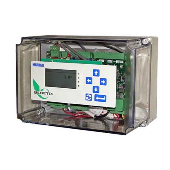
Page 7: Operation
OPERATION LCD User Interface The LCD User Interface assembly is one of many User Interface options for the Genetix controller. It consists of a small, backlit LCD display and a membrane keypad as shown in the photo below. There are two lines of process information shown on the screen, and these may be configured by the user. -
Page 8: Numeric Entry
Moving up one menu level, or aborting an operation is accomplished by pressing the Menu/Esc key. Ultimately, if you continue to press the Menu/Esc key, you will arrive back at the Main Screen. Numeric Entry Various numeric parameters are set and/or changed using the common Numeric Data Entry screen. - Page 9 Page 9 of 104...
-
Page 10: Menu System
Menu System When you first enter the Menu system by pressing the Enter key, you will see the following Main Menu: Feeder Control… ↑ Calibration… Warnings… Faults… Display Settings… Basic Setup… Advanced Setup… Reset Totals… DNA Key… Diagnostics… Drag Chain Control… ↓... -
Page 11: Start [Stop] Feeder
Start [Stop] Feeder If Local control has been selected for the control Source (see Main Menu > Advanced Set-up > Feeder Control > Source), this menu item allows you to start and stop the feeder. If the feeder is not running, this item will read “Start Feeder”. If the feeder has already been started, this item will read “Stop Feeder”. -
Page 12: Calibration
Calibration (Main Menu) Selecting this item from the Main menu will present a screen asking you to enter a Password. The default factory setting for the Calibration password is “1234”. Upon successful entry of the password, you will be presented with the following list of options: Zero Procedure…... -
Page 13: Zero Procedure
Zero Procedure (Main Menu > Calibration > Zero Procedure) This procedure “zeroes” the feeder calibration, accounting for all the dead load represented by the suspension, the belt, etc. Selection of this procedure from the above menu presents a screen that advises you to “Verify belt is empty”, and the current status of the test (0.0%). - Page 14 The Weight Procedure requires the placement of certified test weights directly to the scale suspension, usually as provided by Merrick. For assistance with correct use of Test Weights refer to the feeder Instruction Manual and/or the mechanical drawings provided by Merrick.
-
Page 15: Chain Procedure
The Weight Procedure requires the placement of a certified test chain onto the feeder belt, usually as provided by Merrick. For assistance with correct use of a Test Chain refer to the feeder Instruction Manual and/or the mechanical drawings provided by Merrick. -
Page 16: Speed Span
Calibration procedures. Note: Before you perform a Speed Span procedure, you must measure the belt accurately and enter the Belt Length into the Genetix controller (see Calibration > Numeric Data > Belt Length). Also the Speed Span procedure must be performed before all other calibration procedures. -
Page 17: Material Test
Genetix. For example, if the Genetix controlled feeder is to have an accuracy of +/- 0.25%, the reference scale should have an accuracy of +/- 0.10%. -
Page 18: Ecal Procedure
Error, % = (GCM Total – Actual Total) / Actual Total x 100% So, if for example you believe the Genetix is reading 1% low, you can correct it directly by selecting appropriate numbers and running the Material Test procedure. In this example a set of numbers can be selected by entering a GCM total that is exactly 1% lower than the Actual total, for example GCM Total = 198, Actual Total = 200. -
Page 19: Ecal Factor
It can be estimated depending on the length of the belt, type of tacho, diameter of the pulley, etc. However, it will be accurately determined by the Genetix controller during a Speed Span procedure (see Calibration > Speed Span). You do not have to make an accurate calculation of this parameter and enter it, but you may refer to it here. - Page 20 However, it will be accurately determined by the Genetix controller during a Speed Span procedure (see Calibration > Speed Span). You do not have to make an accurate calculation of this parameter and enter it, but you may refer to it here.
- Page 21 This is the calculated output of the weighing mechanism in mV/V (millivolts per volt) at Design Load, for loadcell number 1. This can be difficult to calculate accurately and will usually be done by Merrick. However, in general, it can be calculated as follows...
- Page 22 Good candidates for Zero Tracking are those feeders or conveyors that occasionally run empty for the period of time necessary to perform a Zero test, and those belt scales that require the utmost accuracy (i.e. certified scales). Following are the list of parameters involved in Zero Tracking, and how to properly set them.
-
Page 23: Warnings
those of Load (i.e. lb/ft, kg/m). To prevent zeroing a belt when material may actually be present, this value should be set very low. Absolute Limit This parameter is the maximum allowed total change of the Zero Load. As successive Zero Tracking processes are performed, the sum of all tests is accumulated. -
Page 24: Faults
Selecting “Warnings” from the Main Menu will present a screen that shows a list of all Logical Inputs and Logical Outputs that have had their “Warning” property set. Next to each input or output, you will see one of the following labels, Label Meaning <blank>... -
Page 25: Display Settings
Label Meaning <blank> No Fault has occurred (since last reset) “Fault-Off” Fault occurred, but is not now present (may be reset) “Fault-ON” Fault occurred and is still present If a Logical I/O point shows the label “Fault-Off”, that means that condition did occur but is no longer present. -
Page 26: Lower
Feedrate ↑ Speed Load Grand Total Sub-Total Belt Spd Demand Time Setpoint ↓ Lower (Main Menu > Display Settings) This item allows you to select what variable is displayed on the lower line of the main screen. You may select from the same list as above. Note: While at the main screen, it is also possible to scroll the lower display through the available options with the Up/Down arrow keys. -
Page 27: Basic Setup
Basic Setup These are the basic parameters for all Belt applications. Selecting this item from the Main menu will present a screen asking you to enter a Password. The default factory setting is “5678”. Upon successful entry of the password, you will be presented with the following list of parameters: Units…... -
Page 28: Design Capacities
(Main Menu > Advanced Setup) These are the more advanced settings for all Belt applications. These settings are typically configured at the factory (by Merrick), and so it is possible you may not need to change them. Selecting this item from the Main menu will present a screen asking you to enter a Password. -
Page 29: Feeder Control
Feeder Control… ↑ Limits… Load Cells… Tachos… Process Control… Analog I/O… Digital I/O… Totalizer… Feeder Peripherals… Communications… Date & Time… Passwords… GCM Name… Direct Param Edit… Configuration… ↓ Note: Some of the above items may not appear, depending on the Configuration settings (see Main Menu >... - Page 30 Control… ↑ Source… Method… Settings… ↓ Control This refers to whether feeder control is to be automatic (uses feedback to control), or manual (Belt Speed Demand is manually entered). The two choices for this setting are: Manual ↑ Auto ↓ Manual With this control option selected, you must enter the desired Belt Speed Demand from the keypad.
- Page 31 Local ↑ Remote (Analog) Network (Serial) ↓ Local “Local” refers to control from the User Interface. Once you set the control source to Local, the Feeder Control menu (see Main Menu > Feeder Control) is used to start and stop the feeder and enter the setpoint. Remote (Analog) “Remote (Analog)”...
- Page 32 Rate Control If set for “Rate Control”, feedrate is the controlled variable. The controller will attempt to maintain a feedrate setpoint. Speed Control If set for “Speed Control”, belt speed is the controlled variable. The controller will attempt to maintain a speed setpoint. Open Loop If set for “Open Loop”...
- Page 33 • The current head load must be greater than 1% of Design Load At start, the Genetix will calculate the desired Belt Speed Demand using the Head Load (belt load), the Setpoint, and the Speed Factor. It will immediately Page 33 of 104...
-
Page 34: Limits
start at this speed, limited only by the acceleration set by the user (see Main Menu > Advanced Setup > Process Control > Accel/Decel). After jumping to this initial speed, closed loop control takes over and regulates the speed appropriately. Numeric Data…... - Page 35 Feedrate The following settings are available for Feedrate limits: High Feedrate ↑ Low Feedrate High Feedrate Delay Low Feedrate Delay High Abs Deviation Low Abs Deviation High Rel Deviation Low Rel Deviation High Deviation Delay Low Deviation Delay ↓ High Feedrate If the actual feedrate exceeds this limit for duration longer than the High Feedrate Delay value (see below) then the logical output “High Feedrate”...
- Page 36 as long as this delay value for the logical output to be set. This delay value is set in seconds. Low Feedrate Delay This value provides a delay for the Low Feedrate limit, in order to prevent nuisance alarms. The feedrate must remain belwo the limit value for duration as long as this delay value for the logical output to be set.
- Page 37 Load The following settings are available for Load limits: High Belt Load ↑ Low Belt Load High Belt Load Delay Low Belt Load Delay ↓ High Belt Load If the actual belt load exceeds this limit for duration longer than the High Belt Load Delay value (see below) then the logical output “High Belt Load”...
- Page 38 Speed The following settings are available for Speed limits: High Belt Speed ↑ Low Belt Speed High Belt Speed Delay Low Belt Speed Delay ↓ High Belt Speed If the actual belt speed exceeds this limit for duration longer than the High Belt Speed Delay value (see below) then the logical output “High Belt Speed”...
- Page 39 Max Rate Setpoint ↑ Min Rate Setpoint Max Rate SP Delay Min Rate SP Delay Max Speed Setpoint Min Speed Setpoint Max Speed SP Delay Min Speed SP Delay ↓ Max Rate Setpoint This is the maximum allowed setpoint, and the logical output “High Setpoint” will be set if it is exceeded for longer than the duration set by the limit “Max Rate SP Delay”...
- Page 40 Max Rate SP Delay This value provides a delay for the High Rate Setpoint limit, in order to prevent nuisance alarms. The feedrate setpoint must remain above the limit value for duration as long as this delay value for the logical output to be set. This delay value is set in seconds.
- Page 41 duration as long as this delay value for the logical output to be set. This delay value is set in seconds. Belt Speed Demand The following settings are available for Belt Speed Demand limits: Note: The following setpoint limits will appear in the menu only if Feeder Control is enabled (see Main Menu >...
-
Page 42: Load Cells
value for duration as long as this delay value for the logical output to be set. This delay value is set in seconds. Min Spd Demand Delay This value provides a delay for the Min Belt Speed Demand limit, in order to prevent nuisance alarms. - Page 43 While in Inferred Load mode, the load is not being measured but rather is set to a value that has been established by the Genetix controller based on history, or can be set by the user. Once the problem is corrected, the controller can be switched back to gravimetric mode by setting the Load Cell Function back to “Auto Bypass”...
- Page 44 Analog Input Load information is generated by an analog input. Note that the load value must be calibrated using an analog input calibration procedure. Negative load values on the analog input are not allowed and are replaced with zero. This setting is most commonly used when there is a weight transmitter available with a high level (i.e.
- Page 45 Inferred Load This is the value that will be used for belt load, if in Inferred Load mode. This can be a result of either the user selecting “Inferred Load” as the load cell function (see Main Menu > Advanced Setup > Load Cells > Function ), or as a result of a load imbalance if “Auto Bypass has been selected as the load cell function.
-
Page 46: Tachos
Tachos (Main Menu > Advanced Setup > Tachos) Selecting this menu item, you will be presented with the following menu: Function… ↑ Tacho 1 Tacho 2 Numeric Data… ↓ Note: Not all menu items will appear, depending on how many Tachos are configured (see Main Menu >... - Page 47 Second Only This is the setting to use if you have only one tacho connected and it is connected to the Tacho 2 port on the GCM. This is the tacho that will be used for all functions within the controller. Note: This tacho may be a 2-channel (i.e. quadrature), but it is still considered one tacho.
- Page 48 proximity switch and target) then this can be connected to the second tacho port and used to detect belt slippage or breakage. Note: In conjunction with this setting, the parameter corresponding to how much belt travel to allow without a pulse from the second tacho must be set (see Main Menu >...
- Page 49 The outputs of this encoder must be nominal “TTL” levels (i.e. 0-5 VDC). This is the most common type of encoder used on Merrick belt feeders. F-25/Mag, Ch-A The setting is used with the Merrick F-25 or DSP-825 type 2-wire current loop encoders, and certain other encoders of this style.
- Page 50 Note:This setting turns on a bias current and therefore should not be used if an optical encoder is connected. Damage to the encoder may result. Quad, Opt/Line Drv This setting functions the same as “Quad, Opt/TTL” (see above), but is used with optical encoders that have “Line Driver”...
- Page 51 Tacho 2 All the same settings as for tacho 1 are available for tacho 2. Note: These settings are only available if Tacho 2 is enabled (see Main Menu > Advanced Setup > Configuration > Tacho 2). Numeric Data These are numeric settings that affect the operation of the tachos or the speed detection algorithms of the GCM.
-
Page 52: Process Control
Selection of this menu item shows you the list of parameters that are the settings for conventional PID (Proportional plus Integral plus Derivative) control and their current value. PID is the control action that enables the Genetix to maintain the desired setpoint, by constantly striving to minimize the deviation between the... - Page 53 setpoint and the process variable (i.e. Feedrate or Belt Speed). The PID algorithm uses the deviation to calculate a new Belt Speed Demand to bring the feeder to the setpoint. A complete description of how PID control action works is beyond the scope of this Manual, but a brief description of each term is provided below.
- Page 54 Accel/Decel Selection of this menu item shows you the settings that allow you to control how rapidly the Belt Speed Demand signal is allowed to change, and therefore provide a certain amount of dynamic output protection. These parameters are set in percent/second (%/s).
-
Page 55: Analog I/O
Load In some cases the load signal generated by the feeder mechanics is unusable to calculate feedrate as-is because of mechanically generated noise, for example excessive ambient vibration. In these cases, a sliding average algorithm calculates an average load with less noise. This parameter is settable between 1 and 33 slots, with 1 representing no averaging. -
Page 56: Inputs
Inputs… ↑ Outputs… ↓ Inputs (Main Menu > Advanced Setup > Analog I/O > Inputs) Selecting Inputs from the Analog I/O menu will present you with the following menu: Analog In 1… ↑ Analog In 2… Analog In 3… ↓ Analog In 1 Selection of one of the Analog Inputs above will allow the following settings to be configured:... - Page 57 Feedrate SP If you select this parameter, the analog input received will be mapped to a value representing the desired feedrate (i.e. the Feedrate setpoint). This will be used to control the feeder if the Feeder Control Method is “Rate Control” (see Main Menu >...
- Page 58 Calibration of this analog input and the parameters under Numeric Data (see below). Note, the name of the register used is GLO.AnaInHijack, the number of which will be dependent on the GCM firmware version. Contact Merrick Customer Support for assistance if necessary. Calibration This menu allows you to calibrate the physical analog input for the signal to which it is connected.
- Page 59 High mA ↑ Full Scale Low mA Zero ↓ Selecting any of the above parameters brings up the Numeric Data Entry screen that allows you to assign or edit the numeric value. High mA This is the value that represents the maximum analog signal that will be received.
-
Page 60: Outputs
Outputs (Main Menu > Advanced Setup > Analog I/O > Outputs) Selecting Outputs from the Analog I/O menu will present you with the following menu: Analog Out 1… ↑ Analog Out 2... Analog Out 3... Analog Out 4... Analog Out 5... Analog Out 6... - Page 61 Numeric Data (see below). Note, the name of the register used is GLO.AnaOutHijack, the number of which will be dependent on the GCM firmware version. Contact Merrick Customer Support for assistance if necessary. Always Zero This setting effectively “turns off’...
- Page 62 High mA This is the value that represents the maximum analog signal that will be sent. It is entered in mA (milliamperes). Note the range is nominally 4-20mA, but it is possible to enter numbers outside this range if the connected device cannot be calibrated.
-
Page 63: Digital I/O
Configuration settings (see Main Menu > Advanced Setup > Configuration). Logical inputs are events that occur within the Genetix controller that typically cause some action to take place. An example of a Logical input for a belt feeder would be “Run Permission”, which is required to make the feeder run. - Page 64 Also, the Configuration settings will cause specific Logical inputs to appear or disappear from this menu. Consult the Appendices to this Manual, or contact the Merrick Customer Service department for assistance. Outputs This menu allows you to map the Physical outputs to the Logical outputs. One Logical Output may be mapped to multiple Physical outputs, allowing one internal event to be sent to multiple external processes.
- Page 65 Logical Inputs… ↑ Logical Outputs… ↓ Select one of the above items to show the desired list. Select a Logical I/O point from the list by pressing the Enter key, and you will see the following options: None ↑ Warning Fault ↓...
-
Page 66: Totalizer
No changes should be made unless all equipment is secure and no personnel are at risk. If you have any doubts about this process, contact the Merrick Customer Service department for assistance. -
Page 67: Feeder Peripherals
Totalizer Cutoff ↑ Weight per EMT Pulse EMT Pulse Length ↓ Totalizer Cutoff This setting allows you to specify a value for Belt Load below which totalization will not occur. Totalization is normally bi-directional, meaning that material can be subtracted from the totalizer if belt load is negative. If you wish to prevent this from happening, you may set this value at some reasonable value and any belt load lower than the setting (including negative values) will not be totalized. - Page 68 AtSpd Connected ↓ Overld Connected This is a switch (Y/N) that tells the Genetix that the drive has an overload output and that is connected to a GCM input, which has been mapped to the Logical input “Belt Drv Overld.
- Page 69 AtSpd Connected This is a switch (Y/N) that tells the Genetix that the drive has an “At Speed” output and that is connected to a GCM input, which has been mapped to the Logical input “Belt Drive AtSp”. Numeric Data...
- Page 70 Blocking This is a switch (Y/N) that indicates whether or not it is okay to run the belt forward in Manual mode, while the MOB is indicating that there is material on the belt. If “Blocking” is enabled (“Y”), then this is not allowed. This is a requirement of the NFPA for some coal feeders.
- Page 71 Blocking ↑ ↓ Blocking This is a switch (Y/N) that indicates whether or not it is okay to start the belt in Auto, while the discharge pluggage switch is indicating that there is material in the discharge cavity. If “Blocking” is enabled (“Y”), and this switch is on, the “Ready”...
- Page 72 Linked with Auto Run ↑ Timed (No = Cont) Reversible Has Zero Spd Sw ↓ Linked with Auto Run This is a switch (Y/N) that links the running of the cleanout conveyor with the running of the belt. If this is set for “Y”, the drag chain will only run if the belt is running, and will not run if the belt is not running.
- Page 73 On Time ↑ Off Time Reverse Delay ZSS Off Delay ↓ On Time This is the time, in seconds, that the drag chain will run if set for “Timed” operation ( see Main Menu > Advanced Setup > Feeder Peripherals > Drag Chain >...
- Page 74 Loss of flow will be determined by two methods; a fixed turn-off time delay, and a delay based on the amount of material that passes though the feeder after the initial loss of flow is indicated. The intent is to provide a warning soon after a loss of flow, and then a Fault (i.e.
-
Page 75: Communications
Note, not all protocols are available on all ports. Note: A complete discussion of these protocols details of how to use them for communications with the Genetix controllers is beyond the scope of this Manual. If you require assistance, contact the Merrick Customer Support department or see www.merrick-inc.com/mct... - Page 76 Typically the master is a computer (PC), and the slave is the Genetix controller. It is also possible to use this protocol in a “multi-drop” configuration (i.e. RS- 422/RS-485) that allows one master to talk to several slaves (i.e multiple...
- Page 77 Merrick Common Interface Table (CIT), making it possible monitor and supervise the Genetixcontroller completely. This protocol is commonly used to interface Genetix controllers with a variety of industrial networks, often with the use of protocol converters. Modbus RTU is a binary protocol.
- Page 78 Parity Parity provides basic error detection for serial communications. Master and slave devices must have the same setting for communications to take place. Parity must be selected from one of the following settings: None, Odd, Even. Data bits This is the number of data bits used to represent one byte of data. Master and slave devices must have the same setting for communications to take place.
- Page 79 (i.e. RS-485). If multiple Genetix GCM’s are connected to one Genetix Color User Interface, each GCM must have a sequential Unit Address, starting at one (1).
- Page 80 The Start Code parameter will only appear in the Numeric Data list if “ScaleNet” has been selected as the protocol. The default value for this is 10, and this should probably not be changed. Certain Merrick applications (i.e. WinMerik®) expect this parameter to be set to 10.
- Page 81 “Small” and “Large”. They represent a data structure containing some fixed elements and some that you can configure. The small data map (CIT) is exactly the same as previous Merrick controllers (i.e. MC³) to maintain compatibility. The large data map exposes some additional data and can be used in more complex systems.
- Page 82 Note that this parameter can also be changed via communications, using the data map. This can be useful if only certain data needs to be written and/or only at certain times. For additional assistance contact the Merrick Customer Support department or see our website www.merrick-inc.com/mct...
- Page 83 This should be done after selecting the correct protocol (see above). Valid values are 0 to 4095 (0xFFF). Note that this parameter can also be changed via communications, using the data map. For additional assistance contact the Merrick Customer Support department or see our website www.merrick-inc.com/mct Integer/Frac FP The Integer/Fraction bits are used when the device using the data (i.e.
- Page 84 Note: In order to select the register number corresponding to the data you want to access, you will need a register list for your GCM application. Contact the Merrick Customer Support department for assistance. Register Tag 2 See Register Tag 1, above.
-
Page 85: Date & Time
GCM Name Each Genetix GCM is allowed to have a unique “friendly” name. This name will be displayed in the top left corner of the User Interface, and may also be used in certain communications modes (i.e. -
Page 86: Direct Param Edit
(Main Menu > Advanced Setup > Direct Param Edit) Note: This menu item allows you direct editing ability for all the parameters in the Genetix controller with very few constraints. It is for the advanced user or Service Technician only. -
Page 87: Configuration
Merrick if necessary. Note: Directly entering register values is very risky, as it is possible to enter a value that will render your Genetix controller inoperative. Again, it is for the advanced user or Service Technician only. - Page 88 Feeder Control ↑ Load Cell 1 Load Cell 2 Tacho 1 Tacho 2 Zero Tracking Belt Tracking Sws Material on Belt Sw Discharge Monitor Drag Chain Belt Index DNA Key Expansion IO Bd 1 Expansion IO Bd 2 Network IO Programmable IO Expansion Analog Card 1 Expansion Analog Card 2...
- Page 89 Feeder Control If this feature is not enabled (is set for “N”), the Genetix cannot function as a feeder, but only as a weigher. An example of an application with this feature disabled is a Belt Conveyor Scale (“Belt Scale”), or a wild flow weigher. In this type of application, the Genetix has no control of the feedrate or speed, but can simply measure what goes across the scale.
- Page 90 (or is not) material on the belt. Various types of switches are used such as paddle, tilt, capacitance, etc. If desired these switches can be connected directly to a Genetix digital input and certain operations can be made to automatically take place when a loss of material occurs.
- Page 91 Expansion IO Bd 1 Expansion IO boards provide the Genetix controller with additional digital inputs and outputs. To inform the Genetix that these additional IO points exist, and are therefore accessible to the controller, this feature must be enabled. Expansion IO Bd 2...
- Page 92 Otherwise Programmable I/O will not appear in the list of Logical I/O. Expansion Analog Card 1 Some Genetix controllers are provided with an auxiliary analog card that can either be plugged into the expansion header on the GCM as a daughtercard, or panel mounted and connected to the GCM via a cable.
- Page 93 Note: you must enter the distance from the suspension to the head pulley (see Main Menu > Advanced Setup > Load Cells > Numeric Data > LC to Head Pulley) for the Genetix to know how to make this translation. This menu item will appear if this feature is enabled.
-
Page 94: Reset Totals
(or “inclination”) of the conveyor or feeder relative to horizontal. Connected to an analog input on a GCM, this will allow the Genetix controller to correctly measure the belt load regardless of angle. This might be useful, for example if the scale or feeder is installed such that this angle changes during operation. -
Page 95: Save To Key.
If you select this option from the above menu, you will see a screen warning you that all data in the Genetix GCM will be overwritten by the data on the present DNA Key. Note: Once the data is written to the GCM from the DNA Key, the GCM will automatically be reset, making the new settings effective. -
Page 96: Diagnostics
If you confirm, all of the data on the present DNA Key will be written to the Genetix GCM will be overwritten, re-configuring it. If successful, the Help message will read, “Reading data”, and then, “Successful Restore” Diagnostics (Main Menu > Diagnostics) Selection of “Diagnostics”... -
Page 97: Start [Stop] Drag Chain
Start [Stop] Drag Chain… ↑ Jog Forward Jog Reverse ↓ Start [Stop] Drag Chain If the drag chain is not linked to Feeder Running (see Main Menu > Advanced Set-up > Feeder Peripherals > Drag Chain > Settings), or if feeder is in Manual mode, this menu item allows you to start and stop the drag chain. -
Page 98: Appendix A
Appendix A Logical Inputs This is a list of all Logical inputs that are available in the Genetix controller. Note: Not all inputs will be visible, depending on the Configuration settings (see Main Menu > Advanced Setup > Configuration). The following Logical inputs are always available, regardless of Configuration settings. - Page 99 Discharge Pluggage Switch related. Present when “Discharge Monitor” is enabled (see Main Menu > Advanced Setup > Configuration > Discharge Monitor). Disch Monitor Discharge Pluggage detected Material On Belt Switch related. Present when “Material on Belt Sw” is enabled (see Main Menu > Advanced Setup > Configuration > Material on Belt Sw). Material On Blt There is material on the belt Flow monitor related.
-
Page 100: Appendix B
Appendix B Logical Outputs This is a list of all Logical outputs that are available in the Genetix controller. Note: Its possible some outputs will not be visible, depending on the Configuration settings (see Main Menu > Advanced Setup > Configuration). - Page 101 Feeder related outputs. Present when “Feeder Control” is enabled (see Main Menu > Advanced Setup > Configuration > Feeder Control). High Deviation Feedrate is higher than max deviation limit Low Deviation Feedrate is lower than max deviation limit High Setpoint High Setpoint limit Low Setpoint Low Setpoint limit...
- Page 102 Peripherals > Infeed Flow Monitor > Numeric Data ). Feeder must be in Auto and must be running. When a loss of flow is detected (logical input “Low Infeed Flow” turns on, an internal totalizer is started. If this totalizer exceeds the set amount, the logical output “Empty Pipe”...
-
Page 103: Appendix C
Appendix C GCM Connections Consult your Merrick wiring diagram for additional connection information, or contact the Merrick Customer Support department for assistance. Page 103 of 104... -
Page 104: Appendix D
Appendix D GCM Specifications Environmental Maximum ambient temperature: 50°C (122°F) Minimum ambient temperature: -10°C (14°F) Power Supply voltage: 24 VDC +/- 1V Power consumption: 8W nominal, 12W maximum Power dissipation: 5W nominal, 10W maximum Loadcell Inputs (2) Excitation voltage: 5 VDC Excitation current: 300mA (max) Tachos (2) Supply voltage: 5 VDC...
Need help?
Do you have a question about the Genetix and is the answer not in the manual?
Questions and answers