Table of Contents
Advertisement
Quick Links
Advertisement
Table of Contents

Related Manuals for Eurotron MicroCal 20 Series


Summary of Contents for Eurotron MicroCal 20 Series
- Page 1 ENGLISH http://www.eurotron.com 2 channels multifunction calibrators MicroCal 20 - MicroCal 20 IS MicroCal P20 - MicroCal P20 IS MicroCal 20T Instruction Manual MM850432 ed. 05c...
- Page 2 Eurotron has used the best care and efforts in preparing this book and believes the information in this publication are accurate. The Eurotron products are subjected to continuous improvement, in order to pursue the technological leadership; these improvements could require changes to the information of this book.
-
Page 3: Table Of Contents
Instruction Manual MM850432 ed. 05 5.5.5 Temperature Unit Setting ..... 44 CONTENTS CALIBRATION PROCEDURES ..89 5.5.6 Current ..........44 5.5.7 Voltage..........46 DLL DRIVER FOR WINDOWS™..92 5.5.8 Math Functions ........47 10.1 Function and Property......92 IMPORTANT NOTE ......5 5.5.9 Pressure.......... - Page 4 Instruction Manual MM850432 ed. 05c 15.1 IS model specifications.......114 CERTIFICATES .......112 CERTIFICATES .......118 15.2 ATEX Specifications ......115 14.1 Warranty terms ........112 16.1 Warranty terms........118 15.3 Instructions for use ......116 14.2 Letter of conformity......112 16.2 Consumer notice ........ 118 15.3.1 Recharging the batteries ....116 16.3 Letter of conformity ......
-
Page 5: Important Note
-MH BATTERIES . DO-NOT ECHARGEABLE BATTERIES MUST BE RECYCLED OR DISPOSED FOR PROPERLY AY EXPLODE IF DAMAGED OR DISPOSED OF IN FIRE SHORT CIRCUIT CAUTION: EUROTRON I USE CHARGER SUPPLIED BY NSTRUMENTS ONLY ! WARNING ! RIMARY ELEMENTS THERMOCOUPLES RESISTANCE THERMOMETERS... -
Page 6: Warnings For Is Models
Batteries must ONLY be fitted in a SAFE AREA. If fitted with rechargeable batteries, the batteries must ONLY be charged in a safe area and only with the Eurotron charger supplied for use with the Multi-Calibrator. The RS232 communication circuit may only be used outside the hazardous area. -
Page 7: General
Report of Calibration Each MicroCal is factory calibrated and certified against Eurotron Standards, which are periodically certified by an Internationally recognised Laboratory to ensure traceability, and shipped with a Report of Calibration stating the nominal and actual values and the deviation errors. -
Page 8: Ordering Code
Standard packaging includes: MicroCal 20 DPC IS XP calibrator (±0.006% rdg accuracy, multifunction CH1 IN + CH2 IN/OUT, 1 or 2 internal pressure capability, external sensor connector), rubber holster, battery charger, instruction manual, and Eurotron Report of calibration. Table A... -
Page 9: Microcal 20T Codes
2.2.2 MicroCal 20T codes Cat. 3120 A – BBB - C Standard packaging includes: MicroCal 20T calibrator, rubber holster, dual input channels, battery charger, instruction manual, and Eurotron Report of calibration. Table A Line charger 120V 50/60Hz with USA plug... -
Page 10: Microcal P20 Codes
Standard packaging includes: MicroCal P20 basic calibrator (2 internal sensors + external sensor pressure connector), battery charger, instruction manual, and Eurotron Report of calibration. Cat. 3240 plus AA - B - C - D Standard packaging includes: MicroCal P20 plus calibrator (2 internal sensors + external sensor pressure connector + mA/V/Pt100 input/output), battery charger, instruction manual, and Eurotron Report of calibration. -
Page 11: Accessories
Instruction Manual MM850432 ed. 05 Accessories F3280010 External pneumatic hand pump –0.95 to 40 bar EXTERNAL PRESSURE MODULES - AISI 316SS - ±0.025% F.S. F3280015 External Hydraulic hand pump 700 bar GAUGE BB480009 from -100 to 100 mbar (1.5 PSI) res. 0.001mbar F3280016 External Hydraulic hand pump 1000 bar BB480010... -
Page 12: Technical Specifications
Instruction Manual MM850432 ed. 05c Technical specifications 2.4.1 MicroCal 20 DPC 0 to 50 mA 0.1 µA ±(0.01% rdg + 0.4 µA) ±(0.02% rdg + 0.4 µA) NOTE: . 15 FOR THE MODELS SEE CHAPTER Notes: limited to 21 mA max on passive current loop (the Microcal supply IN/OUT Voltage the Tag). - Page 13 Instruction Manual MM850432 ed. 05 Pt100 -200 / 850°C 0.01 °C ±(0.01% +0.05°C) ±(0.02% +0.05°C) IN/OUT Thermocouples OIML -330 / 1570°F 0.01 °F ±(0.01% +0.09°F) ±(0.02% +0.09°F) TC TYPE RANGE RESOL. ACCURACY ACCURACY Pt100 -200 / 850°C 0.01 °C ±(0.01% +0.05°C) ±(0.02% +0.05°C) Plus / XP models BASIC model...
- Page 14 Instruction Manual MM850432 ed. 05c Temperature compensation: Automatic with built-in calibration matrix from 0°C to Sensor type: 50°C. Range: 0 to 95% RH Engineering units: mbar, bar, Pa, hPa, kPa, MPa, kg/cm2, kg/m2, psi, mmH2O, Accuracy: ±2% RH cmH2O, mH2O, Torr, atm, lb/ft2, inH2O, ftH2O, inH2O@4°C, ftH2O@4°C, mmHg, Pressure: cmHg, mHg, inHg, programmable.
- Page 15 Instruction Manual MM850432 ed. 05 Power supply: external charger and rechargeable Ni-MH battery Battery life (typical): 10 h (8 h on IS models) on Tc and mV input/output (backlight Off) 4 h (3 h on IS models) with 20 mA simulation (backlight Off) Recharging time (typical): 5 h (8 h on IS models) at 90% and 6 h (10 h on IS models) at 99% with instrument switched off.
-
Page 16: Microcal P20
Instruction Manual MM850432 ed. 05c 2.4.2 MicroCal P20 0 to 5000 Ω 10 mΩ ±(0.01% rdg + 120 mΩ) NOTE: FOR THE MODEL SEE CHAPTER IN/OUT Voltage RTDs IN mode RANGE RES. ACCURACY RTD TYPE RANGE RES. ACCURACY Plus model Plus model 1 µV ±(0.01% rdg + 3 µV) - Page 17 Instruction Manual MM850432 ed. 05 BB480019 0 to 700 bar 10 mbar ±0.25 % F.S. IN Frequency/Pulse RANGE RESOL. ACCURACY Overpressure: 125% F.S. Plus model Port: ¼ BSPM (male) 1 to 200 Hz 0.001 Hz ±(0.005% rdg + 0.001 Hz) Connection wire length: 2 meters 1 to 2000 Hz 0.01 Hz...
- Page 18 Instruction Manual MM850432 ed. 05c Measurement sampling time: 250 ms Display: graphic LCD display with automatic and manual backlight device Digital interface: full bi-directional RS232 Power supply: external charger and rechargeable Ni-MH battery Battery life (typical): 10 h (8 h on IS models) on Tc and mV input/output (backlight Off) 4 h (4 h on IS models) with 20 mA simulation (backlight Off) Recharging time (typical): 5 h (8 h on IS models) at 90% and 6 h (10 h on IS models) at 99% with instrument switched off.
-
Page 19: Microcal 20T
Instruction Manual MM850432 ed. 05 2.4.3 MicroCal 20T RTDs IN mode IN Voltage RANGE RES. ACCURACY RTD TYPE RANGE RES. ACCURACY Plus model (% rdg) -20 to 200 mV 1 µV ±(0.01% rdg + 3 µV) Pt100 -200 / 850°C 0.01 °C ±(0.01% +0.05°C) -0.2 to 2 V... - Page 20 Instruction Manual MM850432 ed. 05c Range: IN Thermocouples Accuracy: TC TYPE RANGE RESOL. ACCURACY Relative Humidity: Plus model Tc J -210 to 1200 °C 0.01 °C ±(0.01% +0.1°C) Sensor type: -35 to 2200 °F 0.01 °F Range: 0 to 95% RH ±(0.01% +0.2°F) Tc K -270 to 1370 °C...
- Page 21 Instruction Manual MM850432 ed. 05 Battery charge indication: bar graph on the LCD display (flashing on charge) Line operation: 100V - 120 V - 230V - 240 Vac with the external battery charger Line transformer insulation: 2500 Vac Sealing: IP54 Operating environment temperature range: from -10 °C to +55 °C Storage temperature range: from 0 °C to +60 °C (excluding batteries) Humidity: max 95%RH non condensing...
-
Page 22: Description
4-wire resistance thermometer Resistance and temperature with resistance thermometer may be measured on a 2, 3 and 4 wire connections for best accuracy and resolution (0.01°C). Eurotron Patent n.206327 is used for the active simulation circuit. Rj compensation Accurate and fast response compensation, through a special low thermal capacity design of binding posts, incorporating a thin film high accuracy Pt100 as cold junction reference. The internal reference allows the maximum accuracy for the -10°C to +55°C temperature range. - Page 23 Instruction Manual MM850432 ed. 05 • Single and continuous cycle with Start, End, Rises, Soaks, and Falls programmable parameters; • the signal value setting uses a unique in-line single-digit setting mode or a direct numeric entry; • direct keyboard access to n.10 programmable memory stored values; Programmable signal converter (TRX) The instrument can be used as a temporary signal converter replacement.
- Page 24 "As left" values) can be memory stored. Upload your calibration data back to your PC. Print reports or export data. CalpMan 2007 calibration procedure manager, is designed to support all Eurotron portable calibrators. It includes an instrumentation database which makes it quick and easy to generate and manage calibration procedures, set and read data from Eurotron calibrators, store the data on a database and generate a calibration report.
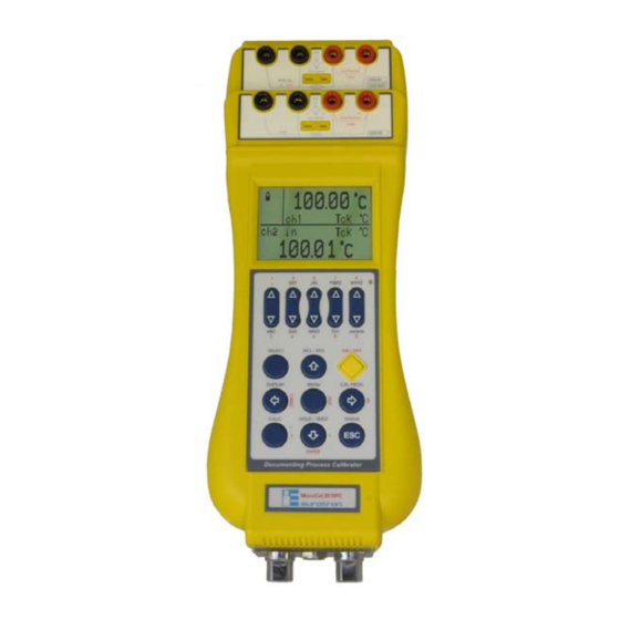
- Page 25 Instruction Manual MM850432 ed. 05 1. Channel 1 Multiconnection binding post 2. Channel 2 Multiconnection binding post 3. LCD graphic display 4. Automatic backlight sensor (not available on IS models) 5. Keyboard 6. HP Pressure input - 1/8” BSPF 7. LP Pressure input - 1/8” BSPF 8.
-
Page 26: Keyboard
Instruction Manual MM850432 ed. 05c Keyboard 5 keys allows you to change (increase/decrease) the relative digit for Channel 2 output mode. [ ], [ ] keys Numeric pad is used when numeric entry is required. Character pad is used when text entry is required, to each pressing the letter changes among the related 3 or 4 ones. -
Page 27: Display
Instruction Manual MM850432 ed. 05 Display The figure shows the features of a typical display. The display shown is in MEASURE and SOURCE mode. The other parts of the display are as follows: • Status box: show the operative mode symbols (see the table below). •... -
Page 28: Power Supply
“–” will appear and the instrument still has about 20 minutes operation capability to end the running analysis. The battery symbol indicates that a full charge is required. Use only the dedicated battery charger supplied by Eurotron together the instrument. - Page 29 Instruction Manual MM850432 ed. 05 MicroCal 20 calibrator is designed to be insensitive to transients or noise, the following recommendations should be followed to reduce ac pick up in the signal leads and to ensure a good performance. The input leads should not be run near ac line wiring, transformers and heating elements. Input/output leads should, if possible, be twisted and shielded with the shield grounded at the end of the cable.
- Page 30 Instruction Manual MM850432 ed. 05c Resistance / Resistenza For a better understanding of the appropriate connection when using the instrument to simulate current into industrial 2-wire loop please, note the meaning of the terminal used. Passive loop This type of connection is to be used when the external loop is not equipped with the loop power supplied. The calibrator can be, as an example, connected directly to a recorder, controller, etc.
-
Page 31: Multi-Connection Binding Post
Instruction Manual MM850432 ed. 05 3.4.1 Multi-connection binding post The MicroCal 20 includes 3 different connection systems: Isothermic connector • Standard banana plugs for TCs • Mini isothermal TC's connector • Push & Lock system for wires Banana plug Push the binding post and insert the wire... -
Page 32: Getting Started
Inspect the instrument for scratches, dents, damage to case corner etc. that may have occurred during shipment. If any mechanical damage is noted, report the damage to the shipping carrier and then notify Eurotron directly or its nearest agent, and retain the damaged packaging for inspection. -
Page 33: Date And Time Setting
Instruction Manual MM850432 ed. 05 Date and time setting Before you use the calibrator for the first time, adjust the current data and time of the unit. • Switch the instrument ON by pressing the [ON/OFF] key. • Press the [MENU] key. MENU MENU Date/Time... -
Page 34: Using The Backlight
Instruction Manual MM850432 ed. 05c • Press the [ ] and [ ] keys to highlight the time display mode (12H or 24H). Press the [ ] key to set the system time. Time Time HH [2] am/pm MM [30] HH [2] MM [30] Press <... -
Page 35: Adjust The Display Contrast
Instruction Manual MM850432 ed. 05 NOTE: THE AUTOMATIC BACKLIGHT SENSOR IS NOT AVAILABLE ON MODELS Adjust the display contrast To increase or decrease the contrast, proceed as follows: • Press [MENU]. • Press the [ ] and [ ] keys to increase and decrease contrast. •... - Page 36 Instruction Manual MM850432 ed. 05c 100.02 100.02 Ch2 Out TcK Rji °C ChP Pl mbar Pl Ch1 10.2 mbar 2 channels Real time graph...
-
Page 37: Operations
Instruction Manual MM850432 ed. 05 OPERATIONS The operating mode (i.e., Source, measure) is shown on the display. Channel 1 can only measure electrical parameters; Channel 2 can Sourcing or Measuring (XP model only) electrical parameter. If internal or external pressure sensors are installed, an additional Pressure channel can be set. When you turn the calibrator ON, it powers up with the last configuration. -
Page 38: Calculator
Instruction Manual MM850432 ed. 05c After memorization of a setup and measure values, those symbols in the status box disappear. To recall one of the memories: • Press for a short time [RCL/STO], “ Rcl ” and appear in the status box •... -
Page 39: Measure Mode
Instruction Manual MM850432 ed. 05 Measure mode 5.5.1 Temperature with Thermocouples The calibrator can support 14 standard of thermocouples. See table on Technical Specifications chapter. Switch the calibrator ON. Select the channel to be configured, proceeding as follows: • Press the [SELECT] key until “SELECT CH1” or “SELECT CH2” is shown. If you choose the Channel 1 settings, the calibrator will If you choose the Channel 2 settings, the calibrator will display: display:... -
Page 40: External Cold Joint Reference Setting
Instruction Manual MM850432 ed. 05c • Press the [ ] and [ ] keys to highlight the “Thermocouple” parameter. • Press the [ ] key to select the option. Press the [ESC] key to return in measure mode without changes. Thermocouple Press <... -
Page 41: Temperature With Rtds
Instruction Manual MM850432 ed. 05 MENU Configuration Unit Ramp-Memory scan Data logger Advanced Press < > to SET • Press the [ ] and [ ] keys to highlight the “Unit” option. • Press the [ ] key to confirm the selection. Press the [ESC] key to return in measure mode without changes. Unit Temperature Temperature... - Page 42 Instruction Manual MM850432 ed. 05c • Press the [SELECT] key until “SELECT CH1” or “SELECT CH2” is shown. If you choose the Channel 1 setting the calibrator will If you choose the Channel 2 setting the calibrator will display: display: N.B.
-
Page 43: Temperature Scale Setting
Instruction Manual MM850432 ed. 05 IMPORTANT LEASE SELECT WIRE CONNECTION IF YOU HAVE A WIRE AND USE THE ELECTRICAL CONNECTION AS SHOWN ON CHAPTER • Press the [ ] key to confirm the selection. Press the [ESC] key to return in measure mode without changes. 3 wire Pt100 IEC Pt200 IEC... -
Page 44: Temperature Unit Setting
Instruction Manual MM850432 ed. 05c 5.5.5 Temperature Unit Setting • Press the [MENU] key. The following page is shown: MENU Unit Configuration Temperature Unit Pressure [mbar] Ramp-Memory scan Xscale Data logger Advanced Press < > to SET Press < > to SET Select the “Unit”... - Page 45 Instruction Manual MM850432 ed. 05 SELECT Ch1 SELECT Ch2 Thermocouple RTD thermometer Current Voltage Resistance Press < > to SET Press < > to SET • Press the [ ] and [ ] keys to highlight the “In” parameter. • Press the [ ] key to select the option.
-
Page 46: Voltage
Instruction Manual MM850432 ed. 05c IMPORTANT CTIVE LOOP SELECTION ALLOWS TO SWITCH OFF THE INTERNA POWER SUPPLY ELECT THIS FUNCTON WHEN YOU DO NOT NEED THE LOOP SUPPLY TO MAXIMIZE THE ICRO AL BATTERY LIFE • Press the [ ] key to confirm the selection and go to measuring mode. Press the [ESC] key to return in measure mode without changes. 5.5.7 Voltage •... -
Page 47: Math Functions
Instruction Manual MM850432 ed. 05 • Press the [ ] and [ ] keys to highlight the “Voltage” parameter. • Press the [ ] key to select the option. Press the [ESC] key to return in measure mode without changes. Voltage 200mV Press <... - Page 48 Instruction Manual MM850432 ed. 05c Thermocouple RTD thermometer Current Voltage Resistance Press < > to SET • Press the [ ] and [ ] keys to highlight the “Process Function” parameter. • Press the [ ] key to select the option. Press the [ESC] key to return in measure mode without changes. Process Function XScale LinMan [ ]...
-
Page 49: Pressure
Instruction Manual MM850432 ed. 05 [ESC] key to return in measure mode without changes. • Press the [ ] key to confirm the selection and go to measuring mode. Press the (for Xscale function, see par.4.3) [ESC] key to return in measure mode without changes. 5.5.9 Pressure •... -
Page 50: Pressure Zeroing
Instruction Manual MM850432 ed. 05c Pressure mbar Press < > to SET • Press the [ ] and [ ] keys to highlight the engineering unit you would like to use in pressure sourcing and measuring. • Press the [ ] key to confirm the selection and going in measuring mode. Press the [ESC] key to return in measure mode without changes. 5.5.11 Pressure Zeroing •... - Page 51 Instruction Manual MM850432 ed. 05 Thermocouple RTD thermometer Current Voltage Resistance Press < > to SET • Press the [ ] and [ ] keys to highlight the “Resistance” parameter. • Press the [ ] key to select the option. Press the [ESC] key to return in measure mode without changes. Resistance 3 wire 4 wire...
-
Page 52: Frequency/Pulse: Measure
Instruction Manual MM850432 ed. 05c 5.5.13 Frequency/Pulse: measure IMPORTANT EASURE OF FREQUENCY OR PULSES IS POSSIBLE ONLY ON CHANNEL • Press the [SELECT] key until “SELECT CH1” is shown SELECT Ch1 Frequency/Pulse Thermocouple Frequency RTD thermometer Pulse Current Voltage Resistance Press <... -
Page 53: Source Mode: Signals Generation
Instruction Manual MM850432 ed. 05 NOTE . 4.6.2 BOUT THE GENERATION OF FREQUENCY PULSE SEE PAR Source mode: signals generation The calibrator can generate (source) all the electrical signals as shown in technical specifications paragraph. • Press the [SELECT] key until “SELECT CH2” is shown. SELECT Ch2 0.000 Press <... -
Page 54: Series
MODELS CONNECT THE TEMPERATURE GENERATOR IN MicroCal 20 is able to command a temperature generator of MicroCal T series by Eurotron. In that way, it is possible to set the temperature directly from the calibrator. Among possible uses, for instance it is possible to realize a system which receives a signal from a temperature transmitter and turns it back on the furnace; moreover, scaling functions are always available. -
Page 55: Frequency/Pulse: Generation
Instruction Manual MM850432 ed. 05 SELECT Ch2 Temp Generator Voltage T100 T200 Resistance T500 Frequency/Pulse T1100 Process Function FAST-CAL Temp Generator Press < > to SET Press < > to SET Press < > to SET Select “OUT”: select "Temp Generator" : Select the desired temperature generator and press the [ ] key to select it •... -
Page 56: X-Scaling Setting
Instruction Manual MM850432 ed. 05c If you select “Frequency” as output, the display shows: If you select “Pulse” as input, the display shows: Frequency Pulse Square OnOff Sinusoidal Time Triangular Mode [One shot] Amplitude [5] Amplitude [5] Sin offset [0] Press <... -
Page 57: Cycle & Ramp
Instruction Manual MM850432 ed. 05 MENU Unit Configuration Temperature Unit Pressure [mbar] Ramp-Memory scan Xscale Data logger Advanced Press < > to SET Press < > to SET Select the “Unit” option Select the “XScale” option. XScale Unit [°C] Parameter [50 mA] In Low [4.000] In High [20.000] Disp Low [0.0]... - Page 58 Instruction Manual MM850432 ed. 05c NOTE . 4.6) EFORE RUN THE PROCEDURE THE HAS TO BE SET AS OUTPUT SEE PAR • Press the [MENU] key. The following page is shown: MENU Ramp - Memory scan Ramp Configuration Ramp OnOff Unit Memory scan n.
- Page 59 Instruction Manual MM850432 ed. 05 See the following explanatory figure: • Select the “On/Off” key to run the procedure. Press [ESC]: the display shows a page like that: 15.2000 Ch2 Ramp 100.02 The “ramp” massage is displayed on the channel 2 while the ramp is running. The phases of the ramp are signed by the arrows beside the “ramp”...
-
Page 60: Data Logging
Instruction Manual MM850432 ed. 05c Data Logging See par.6.1.1 as this function is strictly related to communication with PC 5.10 Graph The graphic display allows showing the real time trend for two channels. The procedure uses channels configuration. Before run the procedure the channels to be graph has to be set. •... -
Page 61: Transmitter Simulator
Instruction Manual MM850432 ed. 05 5.11 Transmitter simulator The calibrator can be programmed for simulate a signal or a pressure transmitter. The input signal is transformed to a 0-20mA or a 4-20mA output signal. The procedure uses channel configuration. Before run the procedure the source channel has to be set. •... - Page 62 Instruction Manual MM850432 ed. 05c • Press the [MENU] key. The following page is shown: MENU Ramp - Memory scan Configuration Ramp Unit Memory scan Ramp-Memory scan Data logger Advanced Press < > to SET Press < > to SET Select “Ramp-Memory scan”...
-
Page 63: Switch Test
Instruction Manual MM850432 ed. 05 • If the sequencer is programmed in “AUTO” mode, press the [HOLD] key to pause and to continue the procedure. • If the sequencer is programmed in “MANUAL” mode, press the [HOLD] key to go to next step. 5.13 Switch Test Verifying functions are available for measurement’s instruments of temperature or pressure. -
Page 64: Leak Test
Instruction Manual MM850432 ed. 05c Pressure If you have to verify the switch on a pressure, select “Pressure” and the type of the sensor to use, internal or external: If you have to verify the switch on a temperature, select “Temperature” and choose the proper channel. Press <... -
Page 65: Leak Test: File
Instruction Manual MM850432 ed. 05 OnOff: run/stop the test Channel: set the pressure input for the test Wait time: seconds before starting the leak test procedure Leak Time: leak test interval (seconds) • Select "OnOff" to start the test The set waiting time will be start and the following pages will appear Leak Test Leak Test Waiting Time 10... -
Page 66: Alarms
Instruction Manual MM850432 ed. 05c 5.15 Alarms It is possible to enable or disable alarm’s thresholds initially set up by the firm (system alarms) or set custom alarm definable by the user. • Press [MENU], the following page is shown: MENU Configuration Configuration... -
Page 67: Switching On Settings (Power On)
Instruction Manual MM850432 ed. 05 • Set the channel where to have threshold alarms with Channel • Set Min and Max threshold NOTE: UNIT MEASURE IS REFERRED TO THE USED CHANNEL • Enable the alarm with “OnOff” NOTE: IN CASE OF THRESHOLD OVERCOMING AN ACOUSTIC SIGNAL IS EMITTED UNTIL THE SIGNAL COMES BACK RETURN UNDER THRESHOLD OR THE ALARM IS DISABLED 5.16 Switching on settings (Power On) -
Page 68: Serial Communication
Instruction Manual MM850432 ed. 05c SERIAL COMMUNICATION RS232 communication port MicroCal has a standard RS232 serial port for communicating with a PC. Connect the serial cable BB530203 to the MicroCal 20 mini-din connector on the left side as in the figure below: WARNING: RS232 ONLY... -
Page 69: Firmware Upgrade : Stflash
Instruction Manual MM850432 ed. 05 MENU Configuration MENU Configuration Display 9600 19200 Unit Power On [Set Ch] Ramp-Memory scan Date/time 38400 Data logger Rejection [50 Hz] 57600 Baud rate [9600] Advanced 115200 Press < > to SET Press < > to SET Press <... - Page 70 Instruction Manual MM850432 ed. 05c • Connect the instrument to PC through the serial communication cable (BB530203) and turn it on and enter the Firmware Upgrade mode by pressing [MENU]+[ON] • Select the right COM port (Serial port) • Select the same communication velocity (expressed in Baud) either on PC (Baud rate) and on the instrument ATTENTION ET THE SAME BAUD RATE EITHER ON AND THE INSTRUMENT...
-
Page 71: Installation Setup
Instruction Manual MM850432 ed. 05 RS232 – USB ADAPTOR INSTALLATION SETUP The RS232/USB adaptor can be used to directly connect the instrument to a computer without the RS232 serial port, but with the USB port only. The adaptor can be used with PCs under the operating systems Windows™XP and Windows™... - Page 72 Instruction Manual MM850432 ed. 05c • select “No, not this time” to avoid the driver search in internet, then click “Next” to proceed with the installation...
- Page 73 Instruction Manual MM850432 ed. 05 • Select the second option: “Install from a list or a specific location (Advanced)”, then click “Next” • Select the option referring to the following page, flagging “Search for the best driver in these locations”. Press “Browse” to select the file path. •...
-
Page 74: Software
CalpMan 2007 calibration procedure manager is also designed to support all Eurotron portable calibrators. It includes an instrumentation (Standards and Tags) database which makes it quick and easy to generate and manage calibration procedures, set and read data from Eurotron calibrators, store the data on a database and generate a calibration report. - Page 75 Instruction Manual MM850432 ed. 05 CD-ROM drive Microsoft mouse or a compatible one In order to install the program, follow the below procedure: Insert the disk in a CD-ROM drive; From the Windows Start Menu, select <RUN…>; Enter the filename D:SETUP.EXE (eventually, substitute the letter “D” for the disk drive that contains disk) Follow the on screen instructions Once installed, an icon appears in your Windows programs list.
-
Page 76: Data Logger: Data Storing
Instruction Manual MM850432 ed. 05c 8.1.1 Data logger: data storing This section of Utilities Manager allows downloading on PC data stored in the internal memory of your MicroCal. First of all, you should have a data file realized with the instrument itself (Data Logging) The calibrator can be programmed for memory store input channels measurements. -
Page 77: Data Logger: Data Simulation (Replay)
Instruction Manual MM850432 ed. 05 8.1.2 Data logger: data simulation (Replay) Replay function allows recalling stored data in a log file. • Press [MENU]: MENU Data logger Configuration On/Off Unit Source Ramp-Memory scan Time Data logger Name [MyLog] Advanced Replay Press <... -
Page 78: Logman
Instruction Manual MM850432 ed. 05c • Return to the menu, Data Logger / Replay and select newly “On/Off” to eventually end the procedure. Otherwise, the function stops after simulation of all data stored. 8.1.3 LogMan OW IT IS POSSIBLE TO MOVE TO SOFTWARE SECTION TILITIES ANAGER ATTENTION... - Page 79 Instruction Manual MM850432 ed. 05 then an Explorer window appears: • Be sure that the instrument is connected and switched on, press the button Connect...
- Page 80 Instruction Manual MM850432 ed. 05c The figure shows the Explorer window after a connection The window is a complete image of the content of the memory of instrument and PC. In the upper side, you can see the browser for log files into MicroCal memory. In the lower side is instead shown a browser for PC files.
-
Page 81: Certificates
Instruction Manual MM850432 ed. 05 Log File: example of visualization ATTENTION HE VISUALIZATION OF THE FILENAME IN THE XPLORER WINDOW DOES NOT IMPLY THAT DATA INSIDE THEM ARE TRANSFERRED TO O VISUALIZE THE CONTENT YOU HAVE TO KEEP ACTIVE THE CONNECTION TO ICRO To save a file, click on Save button and specify name and position of the file in Excel format (“xls”... - Page 82 Instruction Manual MM850432 ed. 05c Certificates: example of visualization • eventually press the button • to export a certificate press . Then, select the proper format for export (Word, txt, etc…) and the destination...
-
Page 83: Linearization Functions: Linman
Instruction Manual MM850432 ed. 05 8.1.5 Linearization functions: LinMan This section of Utilities Manager allows defining customized linearizations, it means defining new sensors types. To select the proper linearization, see par.4.1.8 about math functions: SELECT Ch1 Math Function File selection Current XScale My Sensor 1... - Page 84 Instruction Manual MM850432 ed. 05c If you want to insert polynomial coefficients for a RTD, you have to select “Set RTD parameters” and insert proper numerical values. ·10 °C , B=-5.802 ·10 °C , C=0 Example: for a Pt100 in the range from 0°C to 850°C, the parameters are the following: R0=100 (resistance in ohm at 0°C), A=3.90802 After defining linearization points, it is possible to show the related graphic through the icon or to save the related file (“mcl”...
- Page 85 Instruction Manual MM850432 ed. 05 then an Explorer window appears • Be sure that the instrument is connected and switched on, press the button Connect...
-
Page 86: Calpman 2007: Off-Line Procedures
Instruction Manual MM850432 ed. 05c The figure shows the Explorer window after a connection The window is a complete image of the content of the memory of instrument and PC. In the upper side, you can see the browser for linearization files into MicroCal memory. In the lower side is instead shown a browser for PC files. -
Page 87: Transfer Calibration Parameters
Instruction Manual MM850432 ed. 05 However, MicroCal 20 allows storing inside itself all parameters needed for calibration procedures: in this case, we speak about off-line procedures as the MicroCal is disconnected from PC and it can be moved on the field to perform the required procedures. About procedures off-line, see the following chapter. Anyway, the CalpMan 2007 manual is still useful for the definition of the procedure. - Page 88 Instruction Manual MM850432 ed. 05c • Select “Upload” through “Offline” button and wait for data transfer Eventually, even from Offline button, it is possible to set the serial port parameters from Options. When necessary, select the options “Delete measure after download” or “Delete all measure before upload”...
-
Page 89: Calibration Procedures
CALIBRATION PROCEDURES Eurotron with CalpMan 2007, coupled with the powerful MicroCal 20 calibrator, grants the possibility to keep these instruments under control. The calibration data for the required instruments can be stored into the MicroCal 20 memory following the instructions detailed in this manual. - Page 90 Instruction Manual MM850432 ed. 05c Direct test of Pressure Transmitters at actual programmed test points or with an automatic calculation of actual errors with inlet pressure in an acceptable deviation band from the Test Point level. NOTE .6.2 ARAMETERS OF AN OFF LINE PROCEDURE MUST BE FIRSTLY TRANSFERRED ON THE ICRO SEE PAR...
- Page 91 Instruction Manual MM850432 ed. 05 Result Found Left Press [ ] to SET • Now it is possible to run the procedure by pressing “Run procedure” and to wait for its completion: OFF_VtoV Ref:5.0000V+0.0125 Ref:Out +5.0000 V Act:In +5.0002 V Limit: +0.0035 Error:...
-
Page 92: Dll Driver For Windows
Instruction Manual MM850432 ed. 05c DLL DRIVER FOR WINDOWS™ This document is related to the analysis and the management of a driver for the MicroCal20 (ordering code EE260222), use DLL technology (dynamic library language) for optimize and simplify the protocol of the communication between PC and MicroCal20. 10.1 Function and Property 10.1.1... -
Page 93: Interfaces
Instruction Manual MM850432 ed. 05 10.3 Interfaces 10.3.1 Indication of the instrument ISDRIVER is a function that returns "READY" if is connected a MicroCal20 with firmware version less than 5.006, instead for the version following it answers therefore: • "3224" -->... -
Page 94: Driver Function Structure
Instruction Manual MM850432 ed. 05c 10.3.3 Driver function structure Methods Parameters Results Description Getdirection 1 or 2 Boolean If Ch1 or Ch2 -> In or Out Getscaleinfo String String setting channel opencomm Serialport Boolean Return true if OK baudrate closecomm Setchn idchn Boolean... -
Page 95: Data
Instruction Manual MM850432 ed. 05 Error Number Error Description Error Number Error Description none zero overrange freq underrange psfail highrj notavail lowrj comm calc nomodule notready noactive overflow hightemp underflow lowtemp overvoltage overcurrent others 10.4 Data 10.4.1 Data structure 10.4.1.1 InstrumentFile The structure InstrumentFile contains: FileName di tipo String;... -
Page 96: Methods Setchn
Instruction Manual MM850432 ed. 05c 10.4.1.2 Methods Setchn The methods Setchn accept those parameters: Idchn 1 IDInstruments Muxchn 0 or 1 Direction 0 In ; 1 Out Stepvalue Values num Scalechn … scale mV low scale mV higth scale v scale mA scale Ohm scale kOhm... -
Page 97: Methods Getmeas_Output
Instruction Manual MM850432 ed. 05 Rtd type PT500 Rtd type PT1000 Rtd type PT1KOIML Rtd type NI100 Rtd type NI120 Rtd type CU10 Rtd type CU100 … 10. Tcrtdeng … °C °F 11. Ohmwire … 4 wire 3 wire Return True if the set is executed 10.4.1.3 Methods Getmeas_output The methods Getmeas_output accept those parameters:... -
Page 98: Configuration
Instruction Manual MM850432 ed. 05c 10.5 Configuration 10.5.1 Operating mode In order to use the Driver : Include the DLL in the development environment Create an instance of Driver.Classdriver object Call the OpenComm method (you must remember that this function only set com parameters without opening it) Execute the instruction Call the CloseComm method Unload Driver.clsdriver... -
Page 99: Applications
Instruction Manual MM850432 ed. 05 APPLICATIONS 11.1 Calibrating a temperature indicator The following procedures will be used to test and calibrate temperature indicators. • Switch the calibrator ON 100.00 °C • Connect the instruments as in figure. • Set the CH2 in output mode and configure it for the desired TC or RTD type (e.g. TC type K). To configure the channel, proceed as follows: Press the [ SELECT ] key until “... -
Page 100: Calibrating A Tc Temperature Transmitter
Instruction Manual MM850432 ed. 05c 11.2 Calibrating a TC temperature transmitter The following procedures will be used to calibrate and test temperature to mA transmitter. EXAMPLE : Transmitter has a TC type K input; 2-wire 4/20 mA output on 0 to 600°C Switch the calibrator ON Connect the instruments as in figure (the calibrator will supply the transmitter). - Page 101 Instruction Manual MM850432 ed. 05 Select “ Function ” parameter and change it to “linear”. Select “ Decimals ” parameter and change it to “2” decimal digits. Set the CH1 in input mode and configure it as XScale (e.g. X1). SELECT Ch1 Thermocouple RTD thermometer...
-
Page 102: Calibrating A Pressure Transmitter
Instruction Manual MM850432 ed. 05c 11.3 Calibrating a pressure transmitter The following procedure is used to test and to calibrate a pressure transmitter 4-20mA EXAMPLE : • Connect the instrument like in the figure beside. In this case, the calibrator powers the transmitter, then connect the input channel (1 or 2) as passive loop. -
Page 103: Rtds Certifications
Instruction Manual MM850432 ed. 05 11.4 RTDs certifications Channel 2 on MicroCal 20 XP and MicroCal T20 models only can be set to measure mode. This option allows using the instrument as a 2 channels high accuracy thermometer. The most important application is to compare one Working Standard with the TC or RTD element using one only instrument. Use the MicroCal T series dry-block temperature calibrator to generate the temperature. -
Page 104: Flow-Charts
Instruction Manual MM850432 ed. 05c FLOW-CHARTS 12.1 Menu key Press the [ MENU ] key. [ ] Unit [°C, °F, K] (use the [ ] and [ ] keys to move the cursor vertically. Press the [ ] key to enter in [ ] Rj Ch1 ext [0.00] the highlighted option. - Page 105 Instruction Manual MM850432 ed. 05 [ ] X4 [ ] [ ] Disp Low [0] [ ] Unit [5chars max] [ ] Disp High [100] [ ] Source [200mV, 2V, 20V, 50mA] [ ] Function [Linear, Square, sqrt, log] [ ] In Low [0.00] [ ] Decimals [0, 1, 2, 3, 4] [ ] In High [0.00] [ ] Ramp- Mem Scan [ ]...
-
Page 106: Select Key
Instruction Manual MM850432 ed. 05c [ ] T4 [ ] User [ ] Math [ ] [ ] OnOff [ ] List [ ] Channel [Ch1, Ch2, Pl, Ph, Pe, RH%, T] [ ] Define [ ] Min [ ] Alarm[ ] [ ] Max [ ] General [Enable, Disable] 12.2... -
Page 107: Settings Channel 2
Instruction Manual MM850432 ed. 05 [ ] Passive loop 20mA [ ] 20Khz [ ] Voltage [ ] [ ] Trigger level [0..5] [ ] 200mV [ ] Pulse [ ] [ ] 2V [ ] Measure [ ] 20V [ ] Trigger Level [0..5] [ ] Resistance [ ] [ ] Time... - Page 108 Instruction Manual MM850432 ed. 05c [ ] Pt100 JIS [ ] Rji [ ] [ ] Cu10 [ ] TcK [ ] Cu100 [ ] TcJ [ ] Ni100 [ ] TcT [ ] Ni120 [ ] TcR [ ] Current [ ] [ ] ….
-
Page 109: Settings Pressure Channel
Instruction Manual MM850432 ed. 05 [ ] Pt100 SAMA [ ] 500 Ω [ ] Pt100 JIS [ ] 5k Ω [ ] Cu10 [ ] 4wire [ ] [ ] Cu100 [ ] 500 Ω [ ] Ni100 [ ] 5k Ω [ ] Ni120 [ ] Math function [ ] [ ] Current [ ]... -
Page 110: Maintenance
MicroCal 20 performs the auto-diagnostic procedure when switched on. When measuring it checks also for anomalous conditions. If the calibrator founds trouble, it displays a message on LCD. Sometimes, these messages correspond to an unrecoverable problem and it is necessary to return the instrument to Eurotron for maintenance. Frequently these messages are referred to a recoverable trouble and can be solved by you. -
Page 111: Status Page
Instruction Manual MM850432 ed. 05 Status page 2 Status page 1 30/09/03 18:30:12 13.2 Status page Build Sep 12 2003 SN 1087358 Pressing [ STATUS ], it is possible to visualize one or more pages representing the system’s status. 40000 mbar Typically, pages like that beside are shown and eventually other pages showing status of external pressure Type g sensors or that one of the ambient module. -
Page 112: Certificates
This warranty applies to the original purchaser only. If the unit should malfunction, it must be returned during the warranty period, transportation prepaid, to Eurotron for evaluation. Upon examination, if the unit is found to be defective it will be repaired or replaced at no charge. - Page 113 Instruction Manual MM850432 ed. 05 Declaration of Conformity Eurotron Instruments S.p.A. We : (Supplier's name) Viale F.lli Casiraghi 409/413 - 20099 Sesto S. Giovanni (MI) - Italy (Address) declare under our sole responsibility that the product : Multifunction Calibrator series MicroCal 20 ( MicroCal 20 DPC –...
-
Page 114: Intrinsic Safety Supplement
Instruction Manual MM850432 ed. 05c INTRINSIC SAFETY SUPPLEMENT The Multi-Calibrator model MICROCAL 20 DPC has been designed for testing and calibration of process instrumentation and portable test equipment. The unit provides data to comply with the ISO 9001 requirements for calibration. The MICROCAL 20 DPC can be used to measure and source analogue and digital signals often used in an industrial environment. -
Page 115: Atex Specifications
Instruction Manual MM850432 ed. 05 Output safety parameters: For any connection including Terminal A of Channel 1 Vo= 17.75 V Io = 85 mA Po= 1.339 Watt Co= 0.478 µF Lo= 10 mH For any connection not including Terminal A of Channel 1, and including Terminal A or Terminal B of Channel 2 Vo= 17.22 V Io = 30 mA... -
Page 116: Instructions For Use
Instruction Manual MM850432 ed. 05c Explosion protection type: the device or connector energetic level has been limited unitl a secure level. By applying the Ui and Um maximum voltages there are no risk to cause sparks in the following condition: •... -
Page 117: Battery Maintenance
“ – ” will appear and the instrument still has about 20 minutes operation capability to end the running analysis. The battery symbol indicates that a full charge is required. Use only the dedicated battery charger supplied by Eurotron together the instrument. -
Page 118: Certificates
This warranty applies to the original purchaser only. If the unit should malfunction, it must be returned during the warranty period, transportation prepaid, to Eurotron for evaluation. Upon examination, if the unit is found to be defective it will be repaired or replaced at no charge. - Page 119 Instruction Manual MM850432 ed. 05 Declaration of Conformity Eurotron Instruments S.p.A. We : (Supplier's name) Viale F.lli Casiraghi 409/413 - 20099 Sesto S. Giovanni (MI) - Italy (Address) declare under our sole responsibility that the product : Multifunction Calibrator MicroCal 20 IS - MicroCal P20 IS (Name and type) Cat.
- Page 120 Instruction Manual MM850432 ed. 05c ATEX Certificate...
- Page 121 Instruction Manual MM850432 ed. 05 INDEX Date and time setting; 33 GETTING STARTED; 32 Declaration of Conformity; 119 Graph; 60 DESCRIPTION; 22 Display; 27 Accessories; 11 Display contrast; 35 Active current loop; 30 Display mode; 35 Alarm; 66 IMPORTANT NOTE; 5 DLL Driver Compatibility with VC++, VBasic e .NET;...
- Page 122 Instruction Manual MM850432 ed. 05c Battery pack replacement; 117 Pressure Unit Setting; 49 Temperature IN with RTDs; 41 model specifications; 114 Protections; 111 Temperature IN with TCs; 39 Recharging the batteries; 116 Temperature Scale; 43 MicroCal 20 IS Temperature Unit; 44 Instructions for use;...
Need help?
Do you have a question about the MicroCal 20 Series and is the answer not in the manual?
Questions and answers