Sierra Wireless AirLink RV50 Series Hardware User's Manual
Hide thumbs
Also See for AirLink RV50 Series:
- User manual (509 pages) ,
- Hardware user's manual (78 pages) ,
- Product manual (47 pages)
Table of Contents
Advertisement
Quick Links
Advertisement
Table of Contents

Related Manuals for Sierra Wireless AirLink RV50 Series


Summary of Contents for Sierra Wireless AirLink RV50 Series
- Page 1 AirLink RV50 Series Hardware User Guide 4117313 Rev 6...
- Page 2 Sierra Wireless accepts no responsibility for damages of any kind resulting from delays or errors in data transmitted or received using the Sierra Wireless product, or for failure of the Sierra Wireless product to transmit or receive such data.
- Page 3 Sierra Wireless product. Patents This product may contain technology developed by or for Sierra Wireless Inc. This product ® includes technology licensed from QUALCOMM .
-
Page 4: Table Of Contents
Contents Introduction to the RV50 Series ..........7 Key Features . - Page 5 Contents Step 4—Connect the Power ..........25 Cable Strain Relief .
- Page 6 AirLink RV50 Series Hardware User Guide Regulatory Information ..........61 Important Information for North American Users .
-
Page 7: Introduction To The Rv50 Series
1: Introduction to the RV50 Series ® ® This hardware user guide is for the Sierra Wireless AirLink RV50 and the RV50X gateways. Table 1-1 compares the two gateways. Features and specifications described in this user guide apply to both gateways unless otherwise noted. - Page 8 AirLink RV50 Series Hardware User Guide • Meets industrial-grade certifications including Class 1 Div 2, Class I Zone 2, MIL- STD-810G, IP64 ingress protection • Supports up to 5 VPN tunnels to support secure communications over cellular networks • Events engine for alert reporting to third party server platforms •...
-
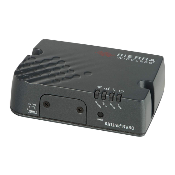
Page 9: Description
Introduction to the RV50 Series Description Back Panel Cellular Antenna Connector 9-pin RS-232 Serial Port Diversity (See Connect the Antennas page 22.) Antenna Connector (See Serial Port on page 24.) (See Connect the Antennas page 22.) Power Connector RJ-45 Ethernet Port USB 2.0 Micro-AB Port (See Connect the Power... -
Page 10: Gateway Configuration And Management
For a complete list of AT Commands, refer to the ALEOS Software Configuration User Guide. Power Modes The AirLink RV50 Series gateway has three power modes: • On—The CPU and the radio are on. The current draw is 900 mW (75 mA @ 12 VDC) when the gateway is idle (i.e. - Page 11 Introduction to the RV50 Series Table 1-2: Power Saving Features Feature Where to configure Notes in ACEmanager Processor Power Services > Power This feature optimizes idle power consumption. Savings Mode Management Recommended for customers who require the best power consumption efficiency, for example in battery or solar powered applications.
-
Page 12: Sample Power Consumption Scenarios
AirLink RV50 Series Hardware User Guide Sample Power Consumption Scenarios Table 1-3: Power Consumption Scenarios Scenario Radio Ethernet Serial GNSS Processor Power Power Power Saving Saving Mode Mode Standby Mode — — — — — — — 53 mW (4.4 mA) Low Power —... -
Page 13: Thermal Output
27.300 Dual SIM The AirLink RV50 Series gateway has two SIM card slots. You can decide which slot is the Primary SIM card. When the gateway is powered on or reboots, it automatically connects to the network associated with the Primary SIM card. If no card is present in that slot, it connects to the network associated with the Secondary SIM card. -
Page 14: Warranty
AirLink RV50 Series Hardware User Guide · Voltage input: 100–240 VAC · Current output: 1.5 A · Part number: 2000492 • DIN rail mounting bracket (See DIN Rail Mount on page 43.) Warranty The RV50 Series gateway comes with a 3-year warranty, and has an optional 2-year warranty extension. -
Page 15: Specifications At A Glance
2: Specifications at a Glance This chapter gives a brief summary of RV50 Series gateway features. For additional information see RV50 Series Specifications on page 47. Certification and Interoperability Emissions / Immunity CE (Including EMC Test case for vehicle installation •... -
Page 16: Rv50 Series Hardware And Software Specifications At A Glance
AirLink RV50 Series Hardware User Guide RV50 Series Hardware and Software Specifications at a Glance Table 2-1: Hardware and Software Specifications Network Technology Radio Frequency Bands on page 47. Host Interfaces 10/100/1000 Base-T RJ-45 Ethernet • RS-232 serial port •... - Page 17 Specifications at a Glance Table 2-1: Hardware and Software Specifications (Continued) Power Consumption page GNSS Technology Channels—Maximum 30 channels (16 GPS, 14 GLONASS), • simultaneous tracking For GNSS bias information, see GNSS Protocol —NMEA 0183 V3.0 • Technology on page 57. Acquisition time: •...
-
Page 18: Environmental Testing
AirLink RV50 Series Hardware User Guide Table 2-1: Hardware and Software Specifications (Continued) Authentication LDAP • RADIUS • TACACS+ • Events Reporting Event Types: digital input, GNSS/AVL, network parameters, • data usage, timer, power, gateway temperature Report types: SMS, email, SNMP trap, relay output, GNSS RAP •... - Page 19 Specifications at a Glance Test Method Category Description IEC 60068-2-32 Free Fall Test 1 m drop height 6 drops onto concrete, 2 per axis: X, Y, Z Operating mode: unpowered IEC 60068-2-70 Marking The markings are rubbed with water for 10 cycles, then Part 2, Test Xb with lubricating oil for 10 cycles.
-
Page 20: Installation And Startup
3: Installation and Startup This chapter shows how to connect, install and start the Sierra Wireless RV50 Series gateway. It also describes the front panel LEDs, and I/O functionality. Note: Field wiring and connections in hazardous locations must be connected as per the wiring methods requirement for Class 2 circuits mentioned in the National Electric Code and the Canadian Electric Code. -
Page 21: Step 1-Insert The Sim Cards
Installation and Startup Step 1—Insert the SIM Cards The AirLink RV50 Series gateway has two mini-SIM (2FF) card slots. The upper slot is Slot 1 and the lower slot is Slot 2. ACEmanager references these slot numbers, and by default, the SIM card in Slot 1 is the Primary SIM card. If you are using only one SIM card, Sierra Wireless recommends that you install it in Slot 1. -
Page 22: Step 2-Connect The Antennas
AirLink RV50 Series Hardware User Guide Step 2—Connect the Antennas The RV50 Series gateway has three SMA female antenna connectors: • Cellular Main antenna connector • Cellular Diversity antenna connector: Required for 4G/LTE networks • GPS antenna connector For regulatory requirements concerning antennas, see Maximum Antenna Gain page 62. -
Page 23: Step 3-Connect The Data Cables
Installation and Startup Diversity antenna connector Cellular antenna connector GPS antenna connector Figure 3-2: Antenna Connectors Table 3-1: Recommended Antenna Separation Service Frequency Wavelength () Best Antenna Good Antenna (MHz) (mm) Separation (mm) Separation (mm) ) ) (1/2 (1/4 1800 2100 2600 WCDMA... - Page 24 AirLink RV50 Series Hardware User Guide USB Port Warning: Do not use the USB port in a potentially explosive environment. Avertissement : N'utilisez pas le port USB dans un environnement potentiellement explosif. • Complies with USB Version 2.0 for high speed operation •...
-
Page 25: Step 4-Connect The Power
— Step 4—Connect the Power The AirLink RV50 Series gateway comes with a 3 meter (10 ft.) DC power cable. You can also purchase an optional AC adapter. Note: Electrical installations are potentially dangerous and should be performed by personnel thoroughly trained in safe electrical wiring procedures. -
Page 26: Fusing
Fusing For DC installations, Sierra Wireless recommends fusing the power input using a 4.0 A fast-acting fuse. DC Voltage Transients The AirLink RV50 Series gateway has built-in protection against vehicle transients including engine cranking (down to 5.0 V) and load dump, so there is no need for external... -
Page 27: Power Connector On The Rv50 Series Gateway
Installation and Startup For DC installations (with a fixed “system” ground reference), Sierra Wireless strongly recommends always grounding the RV50 chassis to this system ground reference. To ensure a good grounding reference, either: • Attach the RV50 to a grounded metallic surface. - Page 28 Note: If you do not connect pin 3 to the ignition, you MUST connect it to the positive terminal of your power supply or battery. If you are using a Sierra Wireless AC adapter, the connection is inside the cable.
-
Page 29: Wiring Diagrams
Pin 1 (Power) —Use the red wire in the DC cable to connect Pin 1 to the power source. Include a 4.0 A fast-acting fuse in the input power line. Sierra Wireless recom- mends using a continuous (unswitched) DC power source. - Page 30 Pin 1 (Power) —Use the red wire in the DC cable to connect Pin 1 to the power source. Include a 4.0 A fast-acting fuse in the input power line. Sierra Wireless recom- mends using a continuous (unswitched) DC power source.
-
Page 31: I/O Configuration
Pin 1 (Power) —Use the red wire in the DC cable to connect Pin 1 to the power source. Include a 4.0 A fast-acting fuse in the input power line. Sierra Wireless recom- mends using a continuous (unswitched) DC power source. - Page 32 AirLink RV50 Series Hardware User Guide You can use Pin 4 in conjunction with events reporting to configure the RV50 Series gateway to send a report when the state of the monitored gateway changes, for example when a switch is opened or closed. For more information, refer to the ALEOS Software Configuration User Guide (Events Reporting chapter).
- Page 33 Installation and Startup Digital Input You can use the green wire to connect Pin 4 to a digital input to detect the state of a switch such as a vehicle ignition, or to monitor an external device such as a motion detector, a remote solar panel, or a remote camera.
- Page 34 AirLink RV50 Series Hardware User Guide High Side Pull-up / Dry Contact Switch Input You can use the green wire to connect Pin 4 to a dry contact switch. The dry contact switch is not available in Standby mode. RV50 Series gateway...
- Page 35 Installation and Startup Analog Input You can use the green wire to connect Pin 4 to an analog sensor. As an analog input (voltage sensing pin), the gateway monitors voltage changes in small increments. This allows you to monitor equipment that reports status as an analog voltage. Pin 4 detects inputs of 0.5–36 V referenced to ground.
- Page 36 AirLink RV50 Series Hardware User Guide Note: The same method is used to sample the input voltage and the internal board temperature for Events Reporting. The significant changes are 300 mV for the input voltage and 1 ºC for the board temperature.
-
Page 37: Step 5-Check The Gateway Operation
— Step 5—Check the gateway operation 1. When power is supplied to the AirLink RV50 Series gateway, it powers up automati- cally, as indicated by the flashing LEDs. If it does not turn on, ensure that the: · Power connector is plugged in and supplying voltage between 7–36 V. -
Page 38: Led Behavior
Solid Amber Fair signal (equivalent to 2 bars) Flashing Amber Poor signal (equivalent to 1 bar) If possible, Sierra Wireless recommends moving the gateway to a location with a better signal. Flashing Red Inadequate (equivalent to 0 bars) Sierra Wireless recommends moving the gateway to a location with a better signal. -
Page 39: Ethernet Leds
Installation and Startup Table 3-10: LED Behavior Color / Pattern Description LED Power Saving Mode Network Solid Green Connected to an LTE network Solid Amber Connected to a 3G or 2G network Flashing Green Connecting to the network Flashing Red No network available Flashing Red / Network Operator Switching is enabled, but the gateway is unable to locate the... - Page 40 AirLink RV50 Series Hardware User Guide Configuring with ACEmanager To access ACEmanager: 1. Connect a laptop to the gateway with an Ethernet cable. 2. Launch your web browser and go to: · https://192.168.13.31:9443 (ALEOS 4.14.0 and later) · http://192.168.13.31:9191 (ALEOS 4.13.0 or previous) Note: It takes the gateway 2–3 minutes to respond after power up.
-
Page 41: Configuring With Amm
Guide. Transitioning from a Raven Gateway If you are transitioning from a Raven XT or Raven XE to an AirLink RV50 Series gateway and you want to maintain a similar level of power consumption, Sierra Wireless recommends the settings outlined in Table 3-11. -
Page 42: Step 7-Mounting The Rv50 Series Gateway
Mounting Brackets The RV50 Series gateway comes with mounting screws. An optional DIN rail mounting bracket (P/N 6000659) is available from Sierra Wireless. Flat Surface Mount If you are mounting the RV50 Series gateway on a flat surface, use the mounting screws that come with the gateway. -
Page 43: Din Rail Mount
Figure 3-19: RV50 Series Gateway Mounting Bracket for Flat Surfaces DIN Rail Mount If you are mounting the RV50 Series gateway on a DIN rail, order DIN rail mounting bracket kit (P/N 6000659) from Sierra Wireless. The kit contains: • L-shaped DIN Rail Mounting Bracket—Qty 1 •... - Page 44 Power Consumption Scenarios on page 12. Note: The DIN rail mounting bracket and clip in the Sierra Wireless kit should only be used on horizontally-mounted DIN rail. Rev. 6 October 2021 4117313...
-
Page 45: Reboot The Rv50 Series Gateway
Installation and Startup Reboot the RV50 Series Gateway To reboot the RV50 Series gateway: • On the gateway, press the Reset button for 1–5 seconds. (Release the button when the Power LED flashes green.) • In ACEmanager, click the Reboot button on the toolbar. Reset the RV50 Series Gateway to Factory Default Settings To reset the gateway to the factory default settings:... - Page 46 AirLink RV50 Series Hardware User Guide • Wait 10 minutes. If no action is taken within 10 minutes of the device entering Recovery mode (for example, if the Recovery screen has not been loaded by the web browser), it automatically reboots and exits Recovery mode.
-
Page 47: Rv50 Series Specifications
4: RV50 Series Specifications This chapter provides the specifications for the standard RV50 and the RV50X. Radio Frequency Bands Use the following table as a guide to the radio frequencies supported by the RV50 and RV50X radio modules. To determine which radio module your gateway has, refer to the label on the bottom of the gateway, or in ACEmanager, go to Status >... - Page 48 AirLink RV50 Series Hardware User Guide Table 4-1: RV50 MC7354 North America (Continued) Radio Band Frequencies Technology Generic Verizon AT&T Sprint Wireless EV-DO BC0 (Cellular 800 MHz) Tx: 824–849 MHz Rx: 869–894 MHz BC1 (PCS 1900 MHz) Tx: 1850–1910 MHz...
- Page 49 RV50 Series Specifications Table 4-2: RV50 MC7304 International Radio Technology Band Frequencies Generic Telstra Band 1 (2100 MHz) Tx: 1920–1980 MHz Rx: 2110– 2170 MHz Band 3 (1800 MHz) Tx: 1710–1785 MHz Rx: 1805–1880 MHz ...
- Page 50 AirLink RV50 Series Hardware User Guide Table 4-3: RV50X Radio Module MC7455 North America and EMEA Radio Band Frequencies Technology Generic Verizon AT&T Sprint Wireless Band 1 Tx: 1920–1980 MHz Rx: 2110–2170 MHz ...
- Page 51 RV50 Series Specifications Table 4-3: RV50X Radio Module MC7455 North America and EMEA Radio Band Frequencies Technology Generic Verizon AT&T Sprint Wireless HSPA+ Band 1 Tx: 1920 –1980 MHz Rx: 2110–2170 MHz Band 2 Tx: 1850–1910 MHz Rx: 1930–1990 MHz...
- Page 52 AirLink RV50 Series Hardware User Guide Table 4-4: RV50X Radio Module MC7430 Asia Pacific Radio Band Frequencies Technology Generic Telstra DoCoMo Band 1 Tx: 1920–1980 MHz Rx: 2110– 2170 MHz Band 3 Tx: 1710–1785 MHz Rx: 1805–1880 MHz...
-
Page 53: Radio Module Conducted Transmit Power
RV50 Series Specifications Table 4-4: RV50X Radio Module MC7430 Asia Pacific (Continued) Radio Band Frequencies Technology Generic Telstra DoCoMo HSPA+ Band 1 Tx: 1920–1980 MHz Rx: 2110–2170 MHz Band 5 Tx: 824–849 MHz Rx: 869–894 MHz ... - Page 54 AirLink RV50 Series Hardware User Guide Table 4-5: RV50 Radio Module MC7354 Conducted Transmit Power (Continued) Band Conducted Tx Notes Power (dBm) GSM / EDGE GSM 850 CS +32±1 GMSK mode, connectorized GSM 900 CS (Class 4) +27±1 8 PSK mode, connectorized...
- Page 55 RV50 Series Specifications Table 4-6: RV50 Radio Module MC7304 Conducted Transmit Power (Continued) Band Conducted Tx Notes Power (dBm) DCS 1800 CS +29±1 GMSK mode, connectorized PCS 1900 CS (Class 4) +26±1 8 PSK mode, connectorized (Class E2) Table 4-7: RV50X Radio Module MC7455 Conducted Transmit Power Band Conducted Tx Notes...
-
Page 56: Carrier Aggregation Combinations
AirLink RV50 Series Hardware User Guide Carrier Aggregation Combinations LTE-Advanced uses carrier aggregation to increase bandwidth. The following tables show the carrier aggregation combinations. Table 4-9: RV50X MC7455 Carrier Aggregation Combinations 1 + 8 2+ 2/5/12/13/29 3 + 7/20 4 + 4/5/12/13/29... -
Page 57: Gnss Technology
RV50 Series Specifications Table 4-10: RV50X MC7430 Carrier Aggregation Combinations 1 + 8/18/19/21 3 + 5/7/19/28 5 + 3/7 7 + 3/5/7/28 8 + 1 18 + 1 19 + 1/3/21 21 + 1/19 28 + 3/7 38 + 38 39 + 39 40 + 40 41 + 41... -
Page 58: Sim Interface
AirLink RV50 Series Hardware User Guide SIM Interface • The RV50 Series gateway has two 6-pin SIM sockets for mini-SIM (2FF) SIM cards, operated at 1.8 V/3.3 V. • This interface is compliant with the applicable 3GPP standards for USIM. -
Page 59: Mechanical Specifications
RV50 Series Specifications Mechanical Specifications Screws used to attach gateway cover Mounting holes 94 mm 85 mm 3.70 in. 3.35 in. Underside view Cellular (RF) antenna connector Power connector Ethernet Serial (RS-232) Rx Diversity 34 mm 1.34 in. GNSS Back view 119.00 mm 4.69 in. -
Page 60: Power Specifications
The device looks for a qualified voltage on this pin as part of the power up sequence. If it doesn’t see a qualified voltage, the device will not turn on. If you are using a Sierra Wireless AC power adapter, the connection is inside the cable. -
Page 61: Regulatory Information
Avertissement : Les changements ou modifications de cet appareil non expressément approuvés par Sierra Wireless peuvent annuler le droit de l'utilisateur à utiliser cet équipement. RF Exposure In accordance with FCC/IC requirements of human exposure to radio frequency fields, the radiating element shall be installed such that a minimum separation distance of 20 cm should be maintained from the antenna and the user's body. - Page 62 N7NMC7455 Bands 7, 41 9 dBi 2417C-MC7455 Sierra Wireless hereby declares the AirLink RV50 Series devices are in compliance with the essential requirements and other relevant provisions of Directive 2014/53/EU. The RV50 Series devices display the CE mark. Warning: Changes or modifications to this device not expressly approved by Sierra Wireless could void the user's authority to operate this equipment.
-
Page 63: Notice For Brazilian Users
RV50X: source.sierrawireless.com/resources/airlink/certification_and_type_approval/ RV50X_ce_declaration_of_conformity/ WEEE Notice If you purchased your AirLink RV50 Series device in Europe, please return it to your dealer or supplier at the end of its life. WEEE products may be recognized by their wheeled bin label on the product label. -
Page 64: Accessories
A: Accessories DC Power Cable (Black Connector) Table A-1: DC Power Cable DC Power Cable Part Number 2000522 Product Release 2016 Components: 1 UL2464 20 AWG × 4 core cable 4 Molex female crimp terminals /AWG 20-24, 250 V, 4 A Max, phosphor bronze tin-plated (part number 43030-0001) ... -
Page 65: Ac Power Adapter (Black Connector)
Accessories AC Power Adapter (Black Connector) Note: Please note that the AC power adapter is not available for sale in New Zealand (as of June 1, 2018). AC Power Adapter Part Number 2000579 Product Release Date 2016 AC Power Adapter Input Table A-2: Input Specifications Minimum Typical... -
Page 66: Ac Power Adapter Environmental Specifications
AirLink RV50 Series Hardware User Guide AC Power Adapter Environmental Specifications Table A-4: AC Power Adapter Environmental Specifications Operating Operating Temperature 0°C ~ 40°C (operates normally) Relative Humidity 10% ~ 90% Altitude Sea level to 2,000 meters Vibration 1.0 mm, 10–55 Hz, 15 minutes per cycle for each axis... -
Page 67: Ac Power Adapter Emc Standards
Accessories AC Power Adapter EMC Standards The power supply meets the radiated and conducted emission requirements for EN55022, FCC Part 15, Class B, GB9254. AC Power Adapter Hazardous Substances • EU Directive 2011/65/EU “RoHS” • EU Directive 2012/19/EU “WEEE” • REACH AC Power Adapter Energy Efficiency The AC adapter complies with International Efficiency Levels, as shown in... -
Page 68: Acronyms
B: Acronyms Acronym or term Definition 3GPP Generation Partnership Project 3GPP unites 6 telecommunications standard development organizations (ARIB, ATIS, CCSA, ETSI, TTA, TTC), and provides their members with a stable environment to produce Reports and Specifications that define 3GPP technologies. Application Programming Interface A protocol intended to be used as an interface by software components to communicate with each other. - Page 69 Acronyms Acronym or term Definition Electronics Industry Association EIA was a standards and trade organization composed as an alliance of trade associations for electronics manufacturers in the United States. They developed standards to ensure the equipment of different manufacturers was compatible and interchangeable.
- Page 70 AirLink RV50 Series Hardware User Guide Acronym or term Definition GPRS General Packet Radio Service A packet-oriented mobile data service on 2G and 3G cellular communication systems. GPRS was originally standardized by European Telecommunications Standards Institute (ETSI) in response to the earlier CDPD and i-mode packet-switched cellular technologies.
- Page 71 Acronyms Acronym or term Definition Light Emitting Diode A semiconductor diode that emits visible or infrared light. Long Term Evolution High performance air interface for cellular mobile communication systems. Point to Point Protocol An alternative communications protocol used between computers, or between computers and routers on the Internet.
- Page 72 AirLink RV50 Series Hardware User Guide Acronym or term Definition UMTS Universal Mobile Telecommunications System A third generation mobile cellular system for networks based on the GSM standard. Developed and maintained by the 3GPP (3rd Generation Partnership Project), UMTS is a component of the International Telecommunications Union IMT-2000 standard set and compares with the CDMA2000 standard set for networks based on the competing cdmaOne technology.
-
Page 73: Index
Index Accessories, 13 Host Interfaces, 16 ACEmanager, 10, 40 Acronyms, 68 AirLink Management Service, 10, 40 ALEOS software, 39 I / O Configuration, 31 Analog input, 35 Input Antenna Analog, 35 Connecting, 22 Dry contact switch, 34 Maximum gain, 62 Ignition switch, 33 Recommended... - Page 74 AirLink RV50 Series Hardware User Guide Power consumption, sample scenarios, 12 Power saving features, 10 Protocols, 17 Pull-up resistor, 34 Pulse counter, 32 Raven XE, 10, 41 Raven XT, 10, 41 Rebooting, 45 Regulatory information, 61 Regulatory specifications, 67 Reliability, 58...
Need help?
Do you have a question about the AirLink RV50 Series and is the answer not in the manual?
Questions and answers