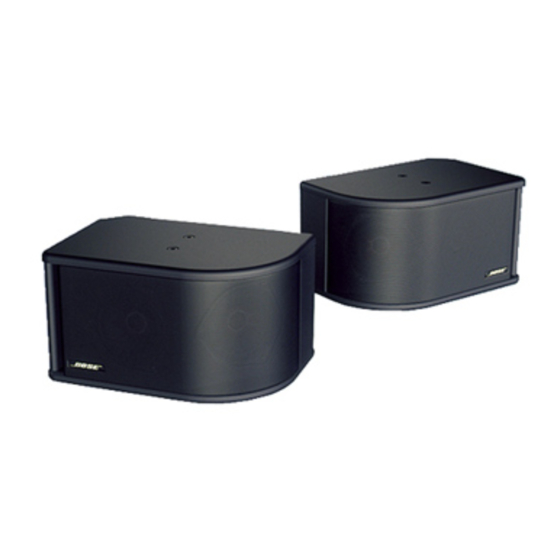
Summary of Contents for Bose 203
- Page 1 ® ® MODEL 203™ LOUDSPEAKER Service Manual ©2010 Bose Corporation Reference Number 193625-SM Rev. 02...
-
Page 2: Table Of Contents
Test Procedures ........................5 Figure 1. Model 203™ Loudspeaker test setup diagram ..............5 Figure 2. Model 203 Loudspeaker Crossover Assembly topside and etch layout diagram ..... 6 Figure 3. Model 203 Loudspeaker Driver wiring diagram ............... 6 Figure 4. Model 203 Loudspeaker Crossover Assembly schematic diagram ......... 7 Model 203 Loudspeaker Crossover Assembly part list (per figure 5) ...... -
Page 3: Specifications
SPECIFICATIONS Model 203™ Loudspeaker Versions: 6 Ohm, 100 Watt, (no transformer)70/100V, 80Watt,(transformer accessory) Impedance: 6 Ohms Nominal, 4.8 minimum from 20Hz to 20kHz. Frequency Range: 60Hz to 16kHz, 3dB Beamwidth: Vertical: 132°Horizontal: 185° Port (each side): Flared slot port tuned to 60 Hz. -
Page 4: Disassembly/Assembly Procedures
5. Crossover Assembly removal 2. Grille replacement 5.1 Remove the grille (1) and angled 2.1 Orient the grille (1) so that the Bose ® driver (3) using procedure 3. logo (14) is aligned with the print on the rear of the cabinet. - Page 5 DISASSEMBLY/ASSEMBLY PROCEDURES (CONT.) 7. Barrier connector removal 7.1 On the rear of the loudspeaker, remove the two (11) screws that secure the barrier connector to the plate (9). 7.2 Grasp the barrier connector and pull it straight out away from the loudspeaker. It should come free.
-
Page 6: Test Procedures
Figure 1. Model 203™ Loudspeaker test minimum. setup diagram 3.4 Listen carefully for air leaks along all Note: Refer to Figure 3. Model 203 driver glue joints, at the binding post connector, wiring diagram for the following procedure. and at both transducer mounting locations. - Page 7 Figure 2. Model 203™ Loudspeaker Crossover Assembly topside and etch layout diagram GREEN BLACK YELLOW BLUE BARRIER STRIP DRIVER Figure 3. Model 203 Loudspeaker Driver wiring diagram...
-
Page 9: Model 203 Loudspeaker Crossover Assembly Part List (Per Figure 5)
Model 203™ Loudspeaker Crossover Assembly part list (per figure 5) Item Reference Description Part Number Number Designator Cap, El, BP, 85, 50V, 20%, 10 uF 290391-100 PTC2 Polyswitch, 60V, 4mm 190348-040 PTC1 Polyswitch, 50V, 4mm 190348-090 Tape, Foil, w/liner 134636 DS1, DS2 Lamp. -
Page 10: Model 203 Loudspeaker Part List (Per Figure 6)
Model 203™ Loudspeaker part list (per figure 6) Item Description Part Number Number Grille, Left, Model 203, Pro Gray 187223-011 Grille, Left, Model 203, Arctic White 187223-021 Grille, Right, Model 203, Pro Gray 187223-012 Grille, Right, Model 203, Arctic White... -
Page 11: Model 203 Loudspeaker Packing List (Per Figure 7)
Model 203™ Loudspeaker packing list (per figure 7) Item Description Part Number Number Manual, Owner’s, Model 203 191913 Bracket, 203, Arctic White 190650-001 Bracket, 203, Pro Grey 190650-003 Packing, End Cap, Model 203 187243-001 Bag, Poly, 13.5x33.5x13x3 mil 114522 Carton, RSC, 300PM... -
Page 12: Optional 70/100V Transformer Accessory Part List And Installation
Notes: 1. To be used with Model 203 pro gray variation only. ® 2. To be used with Model 203 artic white variation only. Transformer accessory installation Choose the positive output lead that best matches your system’s power requirements. Note: Refer to Figure 6 for the following procedure. - Page 13 SERVICE MANUAL REVISION HISTORY Date Revision Description of Change Change Driven By Pages Level Affected 8/97 Document release revision 00 Service manual release 3/02 Part numbers for PTC1 and Part number change PTC2 changed. Part number for the CTV-2 Part number change transformer accessory changed 04/06 Added RoHS part numbers...
- Page 14 SPECIFICATIONS AND FEATURES SUBJECT TO CHANGE WITHOUT NOTICE ® ® Bose Corporation The Mountain Framingham, Massachusetts, USA 01701 P/N 193625-SM REV. 02; 05/10 FOR TECHNICAL ASSISTANCE OR PART ORDERS, CALL 1-800-367-4008...


Need help?
Do you have a question about the 203 and is the answer not in the manual?
Questions and answers