
Related Manuals for Creality Dual Z


Summary of Contents for Creality Dual Z
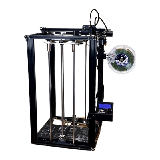
- Page 1 Ender Extender™ 5 Installation Guide for Dual Z, XL and Dual Z XL kits www.enderextender.com 4/21/21 (Demo unit shown, may not reflect final product)
-
Page 2: Table Of Contents
Ender 5 Machine Overview ..............................4 Step 1: Inventory the Kit Contents ............................5 Ender Extender 5XL with Dual Z kit contents ........................5 Step 2: Ender 5 Non-Pro and Pro Differences ........................10 Step 3: Disassemble the Ender 5 ............................10 Step 4: Assemble the base plate ............................ -
Page 3: Document Revision History
Document Revision History Date Revision Summary Apr 21, 2021 Initial document EnderExtender.com – Ender Extender™ 5 Installation Guide Page 2... -
Page 4: Important Safety Instructions
Important Safety Instructions WARNING: ALWAYS DISCONNECT ELECTRICAL POWER FROM THE MACHINE BEFORE PERFORMING ANY MAINTENANCE. SKILL LEVEL: ADVANCED This product is an advanced level project and requires detailed knowledge of the mechanical nature of a 3D printer. Throughout the project, you will be challenged at many levels in order to successfully complete the project. Machine Safety Never reach into the machine’s working area while it is running. -
Page 5: Before You Begin
BEFORE YOU BEGIN Take many pictures of your 3D printer, especially detail areas such as motors, wire connections, switches, screws, nuts, belts, etc. While we have included detailed photos of every step, it is very helpful for you to recall how your specific printer was set up prior to disassembly in preparation for installing the kit. -
Page 6: Step 1: Inventory The Kit Contents
Step 1: Inventory the Kit Contents Your Ender Extender 5 kit includes all the required screws, frame parts, belts and wires that you need for a typical installation. Ender Extender 5XL with Dual Z kit contents Quantity Description Picture Four vertical extrusions... - Page 7 Front lead screw and rods: Lead screw (560 mm) 10mm diameter smooth rods (570 mm) Lead screw nut (4) M3x6 screws Note: Uses 2 Start lead screw and nut 1 set (2) LMK10UU Flange Bearings (8) M4x8 hex cap screws 1 ea Heated bed wire extension and coupler EnderExtender.com –...
- Page 8 Heated bed thermistor extension Nozzle heater extension Nozzle thermistor Page 7 EnderExtender.com – Ender Extender™ 5 Installation Guide...
- Page 9 Fan 1 extension wire Fan 2 extension wire 4 pcs Stepper motor extensions (A) Extruder (B) X Motor (C) Y Motor (D) Z Motor 1 set Pulley and belt set (2) 2GT pulleys (1) 752 mm closed loop belt EnderExtender.com – Ender Extender™ 5 Installation Guide Page 8...
- Page 10 1 set Belt tensioner kit (1) aluminum extrusion bracket (1) M5x40 screw (1) M5 flat washer (2) M5x20 screws (2) M5 star lock washers (2) M5 t-slot nuts (1) printed spacer (2) flange bearings Rod mounting brackets (top/bottom) 1 set Rod mounting bracket hardware (top) (2) M5x20 hex cap screws (2) M5 star lock washers...
-
Page 11: Step 2: Ender 5 Non-Pro And Pro Differences
This type of lead screw will allow the print platform to lower easily on its own after power is turned off. It is believed that with the release of the Ender 5 Pro, Creality adopted a two start lead screw which reduces this tendency for the platform to “self-lower”. - Page 12 Loosen smooth rod mounting screws (4x) from top and bottom supports. Remove the M3 screws (4x) and nuts from the lead screw brass nut Remove the two smooth rods Page 11 EnderExtender.com – Ender Extender™ 5 Installation Guide...
- Page 13 The black carriage plate is ready to be removed. Remove the left/ride flange bearings We will re-use these parts, keep them handy. Set the black carriage plate aside. EnderExtender.com – Ender Extender™ 5 Installation Guide Page 12...
- Page 14 Loosen but do not remove the lead screw set screw Be careful! Do not strip the head. Remove the lead screw from the coupler Set the lead screw aside, it will not be reused. Remove Top front frame member Remove the M5 (2x) screw at the top front corners Remove the M4 (2x) screw at the inside bracket supporting the top front frame...
- Page 15 EnderExtender.com – Ender Extender™ 5 Installation Guide Page 14...
-
Page 16: Step 4: Assemble The Base Plate
Step 4: Assemble the base plate Step Description Gather required parts Original parts: (2) Flange bearings (8) M4x8 screws Kit parts: (2) Flange bearings (8) M4x8 screws (1) Aluminum base plate Page 15 EnderExtender.com – Ender Extender™ 5 Installation Guide... - Page 17 Clean and lubricate the rods and bearings. It is highly recommended to clean the rods, lead screw and bearings. Lubricate with your choice of grease. Insert bearings into the four corners and attach screws. Do not tighten the screws at this time. Locate the brass nuts and screws.
- Page 18 Attach the brass nuts and screws. The brass nuts should mount from the underside of the plate with the long cylinder portion pointing down. Do not tighten the screws at this time. Step 5: Assemble the front rod support brackets Step Description Top Rod Mounting Bracket...
- Page 19 Gather required parts Kit parts: (2) M5x20 hex cap screws (2) M5 lock washers (2) M5 t-slot nuts (1) 2020 rod mounting bracket Affix the M5 lock washers to the M5x20 hex cap screws Insert the M5x20 hex cap screws into the left and right holes in the rod mounting bracket Attach the M5 t-slot nuts, leave enough...
- Page 20 Insert the (2) M4x16 hex cap screws into the flange bearing mounting holes, and attach to the corresponding holes in the bottom rod mounting bracket. Page 19 EnderExtender.com – Ender Extender™ 5 Installation Guide...
- Page 21 Step 6: Assemble the belt tensioner Step Description Gather required parts Kit parts: (2) M5x20 hex cap screws (2) M5 lock washers (2) M5 t-slot nuts (1) 2020 belt tensioner bracket (1) printed bearing support (2) 8mm ID flange bearings (1) M5x40 hex cap screw (1) M5 flat washer Affix the M5 lock washers to the M5x20...
- Page 22 Attach the M5 flat washer to the M5x40 hex cap screw and insert the screw through the printed bearing support. Screw the M5x40 hex cap screw into the tensioner bracket. Ensure the screw is tight but do not over tighten, otherwise you may strip the threads in the bracket.
- Page 23 Lightly tighten the M5 hex cap screws attaching the rod mounting bracket to the top frame member. Attach the bottom rod mounting bracket to the bottom frame member. Center the part and snug the M5x20 hex cap screws to ensure the bracket does not move easily.
- Page 24 Insert the rear 10mm smooth rods through the rear bearings and into the rear rod support mounts. Tighten the bottom rear rod support screws first. Tighten the top rear rod support screws. Page 23 EnderExtender.com – Ender Extender™ 5 Installation Guide...
- Page 25 Insert the 10mm smooth rods into the bottom mounting bracket. Insert the rear lead screw through the brass nut, turning as needed to raise the carriage plate, place the pulley on the end of the lead screw near the Z motor coupler. Insert the lead screw into the Z motor coupler.
- Page 26 Loosen the KFL08 flange bearing set screw so that you can insert the lead screw. Position the closed loop belt over the Z motor coupler and the front flange bearing. You may need to lift the lead screws out of the coupler or the bearing if you’ve already set them into place.
- Page 27 Insert lead screw through the brass nut on the carriage plate. Place the pulley on the end of the lead screw as shown and insert the lead screw into the KFL08 flange bearing, turning the lead screw as needed. Loosely tighten the set screw Attach the top front frame member.
- Page 28 Page 27 EnderExtender.com – Ender Extender™ 5 Installation Guide...
- Page 29 Insert the M5x20 hex cap screws Tighten as needed Insert the inner M4 button head screws Tighten as needed Turn both front and rear lead screws to move the carriage plate all the way to the top of the printer. Using a measuring tool or square, adjust the front and rear height of the bed so that it is evenly positioned.
- Page 30 Position the assembled tensioner unit in between the Z motor bracket and the left rear rod bracket The set screws in both pulleys should be loose. As you perform this step, the lead screws may turn, which will result in the carriage plate becoming uneven.
- Page 31 Loop the belt over the bearing Check alignment of the belt and pulleys. There should be no angle between the pulleys. You must align the pulleys so that they are an even height. While holding tension on the pulley end of the tensioner, tighten the M5 hex cap screws EnderExtender.com –...
- Page 32 One last time let’s check our carriage plate distance front and back. Move the X axis front to back to have a solid measuring point. Turn the lead screw to move the plate up or down. When the carriage plate is even, tighten the pulley set screws.
- Page 33 Remove the end stop switch screw from your original carriage plate and attach it to the new carriage plate Re-attach the heated build platform Set the springs in place Carefully lower the build platform screws through the springs Attach the bed level adjustment wheels EnderExtender.com –...
- Page 34 Hardware and frame assembly are complete! Step 8: Wire extensions If you purchased the XL kit, your kit includes wire extensions which will all attach at the control board and the original wiring harness. Each wire extension is clearly labeled. Remove the bottom cover of the control board, and carefully remove any adhesive applied at the factory securing the connectors to the board.
-
Page 35: Slicer Settings
M211, which controls the firmware’s internal “software endstops” which prevent the machine from exceeding the physical internal limits set by Creality. These limits are 235 (X), 235 (Y), and 250 (Z). This command accepts a parameter (S1 or S0, which means turn the feature on or off). By turning the feature off, we can print beyond the pre-set limits. - Page 36 Highlight the printer profile that you will use with your Ender Extender, and click the button labelled Machine Settings. Note the G28 line in your Start G-Code. If you are using some form of BLTouch or other auto levelling system, we are going to assume you’ve already learned how to update the firmware, so you would be best suited by updating your machine’s X, Y and Z size in the configuration.h file and reflashing.
- Page 37 Note the line M211 S0; disable end stops We need to ensure this line exists after G28 line. These settings will allow the printer to print full size on the larger bed. However, depending on the Cura version, you may have another issue where Cura is forcing you to a small printable area defined by the Ender 3. This “feature” was introduced recently in 2020, and it is rather annoying.
- Page 38 Page 37 EnderExtender.com – Ender Extender™ 5 Installation Guide...
Need help?
Do you have a question about the Dual Z and is the answer not in the manual?
Questions and answers