Table of Contents
Advertisement
Quick Links
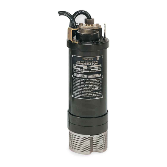
INSTALLATION and OPERATION MANUAL
STANDARD-LINE® Submersible Dewatering Pumps
IMPORTANT!
Read all instructions in this manual before operating pump.
As a result of Crane Pumps & Systems, Inc., constant product improvement program,
product changes may occur. As such Crane Pumps & Systems reserves the right to
change product without prior written notification.
A Crane Co. Company
420 Third Street
Piqua, Ohio 45356
Phone: (937) 778-8947
Fax: (937) 773-7157
www.cranepumps.com
PROSSER
PROSSER
83 West Drive, Bramton
Ontario, Canada L6T 2J6
Phone: (905) 457-6223
Fax: (905) 457-2650
®
Series: 9-81000, 9-81500
9-82500, 9-85000
10HP thru 50HP, 3450RPM
SOME MODELS MAY NOT BE
AVAILABLE
Form No. 096928-Rev. Y
Advertisement
Table of Contents

Related Manuals for Crane PROSSER STANDARD-LINE 9-81000 Series


Summary of Contents for Crane PROSSER STANDARD-LINE 9-81000 Series
- Page 1 Read all instructions in this manual before operating pump. As a result of Crane Pumps & Systems, Inc., constant product improvement program, product changes may occur. As such Crane Pumps & Systems reserves the right to change product without prior written notification. A Crane Co. Company...
-
Page 2: Table Of Contents
Other brand and product names are trademarks or registered trademarks of their respective holders. STANDARD-LINE® is a registered trademark of Crane Pumps & Systems, Inc ® PROSSER is a registered trademark of Crane Pumps & Systems, Inc 1995, 2000, 2002 3/06, 9/06... -
Page 3: Safety First
WARNING! - DO NOT pump hazardous materials IMPORTANT! - Crane Pumps & Systems, Inc. is not (flammable, caustic, etc.) unless the pump is specifically responsible for losses, injury, or death resulting from a designed and designated to handle them. -
Page 4: Pump Specifications
SECTION: A - PUMP SPECIFICATIONS: LIQUID TEMPERATURE .....104°F (40°C) DISCHARGE CASE ......356T6 Aluminum, Hard Anodized DIFFUSER ..........356T6 Aluminum, Hard Anodized SUCTION CASE ........356T6 Aluminum, Hard Anodized with wear resistant polyurethane liner FRAME & OUTER CASE ....6063T6 Aluminum, Hard Anodized PUMP SHAFT ........Stainless Steel IMPELLER .........Hardened 17-4 Stainless Steel HARDWARE ........Stainless Steel O-RINGS ..........Buna... - Page 5 inches (mm) MODEL 9-81000 27.38 (696) 24.00 (610) 9-81500 29.12 (740) 25.75 (654)
- Page 6 inches (mm) MODEL 9-82500 33.95 (862) 30.69 (780) 9-85000 36.68 (932) 33.69 (856)
-
Page 7: General Information
B-4) Service Centers: For the location of the nearest Prosser Service Center, check your Prosser representative or Crane Pumps & Systems, Inc., Service Department in Piqua, Ohio, telephone (937) 778-8947 or Crane Pumps & Systems Canada, Bramton, Ontario, (905) 457-6223. - Page 8 SUPPORT THE PUMP BY ITS ELECTRICAL CABLE ! more different size pumps may be used. Each pump must be treated as an individual unit as far as IT IS VERY IMPORTANT THAT THE FLOW RATE cabling and overload protection is concerned. Individual cables PRODUCED IS WITHIN THE CAPACITY OF THE must be run up to each pump controller for proper protection.
-
Page 9: Start-Up Operation
rated voltage shown on the pump nameplate. C-5.1) Power Cable: D-2) Check Pump Rotation: The cord assembly mounted to the pump must not be Before putting pump into service for the first time, the motor modified in any way except for shortening to a specific rotation must be checked. -
Page 10: Electrical Data
PART NO. VOLT/ NEMA FULL LOCKED CORD CORD CORD WINDING (Nom) START LOAD ROTOR SIZE TYPE RESISTANCE CODE AMPS AMPS W,B--R,B--R,W HH SERIES PUMP w/RAINPROOF CONTROL 9-81032-23 230/3 3450 30.0 208.0 1.100 0.30 -- 0.30 -- 0.30 9-81034-23 460/3 3450 15.0 104.0 12/4... -
Page 11: Preventative Maintenance
valves or the units are spaced. CAUTION ! - When check valves are not used 6.) Shaft Seals: The seals should be inspected every and a series system is accidentally shut down 1500 operating hours for wear (more often if abrasives are present). - Page 12 not, replace stator. WARNING ! - Always wear appropriate clothing and safety gear when working with or around oven. If low stator insulation resistance is due to other modes of failure, such as damaged leads, deformed end turns, etc, the stator should be replaced. Another test of the electrical integrity of the stator is the measurement of winding resistance with an ohmmeter.
- Page 13 adding or removing shims (17a) & (17b) behind the impeller. Figure 8. Examine all seal parts and specifically contact faces. Inspect TABLE 2 - IMPELLER GAP seal for signs of uneven wear pattern on stationary members, PUMP MODEL HP, 60 CYCLE GAP “X”...
- Page 14 FIGURE 9...
- Page 15 (33) and washer (39) from discharge head (22). IMPORTANT! - It is extremely important to keep seal Remove cap screws (31), washers (30, on 10-15HP) or (49, on faces clean during assembly. Dirt particles lodged 25-50HP), from discharge head (22). Carefully, using a plastic between these faces will cause the seal to leak. hammer, tap the discharge case (22) free from the frame assembly and remove while feeding the stator wires through Place spring (10b) over shaft and in place on rotating member...
- Page 16 upward in rotor/shaft assembly. Slide cable grip nut (2b), cable grip (2c), bushing (2d) and This is opposite of downward thrust which occurs when pump cable gland (2e) with o-rings (25) onto cable (2a), and expose is running. “LOOSENESS” between inner and outer race is approximately 3”...
-
Page 17: Replacement Parts
8. Billing Instructions. SECTION: G REPLACEMENT PARTS G-1 SERIAL NUMBER: G-1 ORDERING REPLACEMENT PARTS: The Serial Number block will consists of a six digit number, Your local Prosser distributor can supply parts and repair which is specific to each pump and may be preceded by a service. -
Page 18: Trouble Shooting
TROUBLE SHOOTING CAUTION ! Always disconnect the pump from the electrical power source before handling. If the system fails to operate properly, carefully read instructions and perform maintenance recommendations. If operating problems persist, the following chart may be of assistance in identifying and correcting them: MATCH “CAUSE”... -
Page 19: Cross-Section 9-81000, 9-81500 Series (Fig. 14)
PUMP SERIES: 9-81000, 9-81500 FIGURE 14... -
Page 20: Exploded View 9-81000, 9-81500 Series (Fig. 15)
PUMP SERIES: 9-81000, 9-81500 FIGURE 15... -
Page 21: Parts List 9-81000, 9-81500 Series
PUMP SERIES: 9-81000, 9-81500 PARTS KITS Bearing & Seal Kit ... P/N- 9-815580 () 7, 8, 10, 11, 13, 15, 16, 17a, 17b, 27, 43, 46, 48 O-Ring Kit ......P/N- 9-815574 () 2d, 19, 20, 25, 29, 47, 62, 64 Tools: Seal Pusher... - Page 22 PUMP SERIES: 9-81000, 9-81500 9-815210-2 Shim, .032 Thk. 9-615758 Plug Assy. 2-31003-448 O-Ring 2-31003-366 O-Ring 9-810555 Outer Shell 10HP 9-815555 Outer Shell 15HP 9-615700 Discharge Head 9-815000-1 Strainer Stainless Steel 2-31003-138 O-ring 9-815211 Lockwasher, Impeller .51 x 1.20, Stainless ...
-
Page 23: Cross-Section 9-82500, 9-85000 Series (Fig. 16)
PUMP SERIES: 9-82500, 9-85000 FIGURE 16... -
Page 24: Exploded View 9-82500, 9-85000 Series (Fig. 17)
PUMP SERIES: 9-82500, 9-85000 FIGURE 17... -
Page 25: Parts List 9-82500, 9-85000 Series
PUMP SERIES: 9-82500, 9-85000 2-20009-17 Hex Nut 1/2-13 Zp 002618 Lockwasher #10 Cad PARTS KITS () 7, 8, 10, 11, 13, 15, 16, 17a, 17b, 27, 43, 46, 48 () 7, 8, 10, 11, 13, 15, 16, 17a, 17b, 27, 43, 46, 48 Bearing &... - Page 26 PUMP SERIES: 9-82500, 9-85000 9-850555 Outer Shell 50HP 9-840700 Discharge Head 9-825000-1 Strainer Stainless Steel 2-31003-138 O-ring 9-840211 Lockwasher, Impeller, 25HP, .64 x 1.437, Stainless 2-21016 Lockwasher, Impeller, 50HP, 1 x 1.937, Stainless 2-23012-51 Capscrew 3/8-16 x 1”Lg, Zp 2-12029-1 Connector 230V...
-
Page 27: Nema 3R (Rainproof) Control, Cross-Section & Parts List
NEMA 3R (RainProof) FIGURE 18 625-03556 Retaining Ring Steel PARTS LIST ITEM PART NO. DESCRIPTION 9-840814 Enclosure, NEMA 3R 2-22002-10 Screw 6-32 x .312”Lg. 2-12005-2 Connector, 10-15HP .75”, 230V 2-12005-3 Connector, 10-15HP 1.00”, 460/575V 2-21005-4 Connector, 25-50HP 1.25”, 230/460/575V 2-33065 Connection Diagram 3 Phase 2-22009-16... -
Page 28: Nema 4 (Watertight) Control, Cross-Section & Parts List
NEMA 4 (WaterTight) FIGURE 19 PARTS LIST ITEM PART NO. DESCRIPTION 110. 9-840859-2 Enclosure, NEMA 4 111. 2-33237 Name Plate 112. 2-21002-64 Shim Washer 113. 2-28008-3 Roll Pin 114. 9-840870 Handle 116. 2-32066-23 Caplug, 10-15HP 460/575V 2-32066-30 Caplug, 10-15HP 230V 625-00718 Caplug, 25-50HP 117. -
Page 29: Control Schematic (Fig. 20)
230, 460, 575 Volt, Three Phase Control Panel Schematics FIGURE 20 Galvanic Protection Kit P/N: 9-840572 PARTS LIST PART NO. DESCRIPTION 2-210002-59 Flat Washer, 1/4” Stainless 2-23021-76 HxHd Screw, 1/4-20 x 1.37” lg SS 9-500520 Zinc Anode Sensor Pump must be ordered with the Galvanic Protection Kit to have the correct frame and outer shell. -
Page 30: Series Adapter Kits
Series Adapter Kit Pump Models: 9-81000, 9-81500....P/N: 9-815770 Pump Models: 9-82500, 9-85000....P/N: 9-840770 PARTS LIST P/N: 9-815770 PART NO. DESCRIPTION 2-32015-3 Nipple, Reducer, 4” NPT x 6” Lg 2-32046-1 Coupling, Red, Victaulic, 5” x 4” 1-51-6 Hex Hd. Screw 3/8-16 x 5.50” Lg. Zp 2-23013-84 Hex Hd. -
Page 31: Returned Goods Policy
Crane Pumps & Systems, Inc. Distributor. RETURNED GOODS RETURN OF MERCHANDISE REQUIRES A “RETURNED GOODS AUTHORIZATION”. CONTACT YOUR LOCAL CRANE PUMPS & SYSTEMS, INC. DISTRIBUTOR. Products Returned Must Be Cleaned, Sanitized, Or Decontaminated As Necessary Prior To Shipment, To Insure That Employees Will Not Be Exposed To Health Hazards In Handling Said Material.
Need help?
Do you have a question about the PROSSER STANDARD-LINE 9-81000 Series and is the answer not in the manual?
Questions and answers