Advertisement
Quick Links
Advertisement

Related Manuals for ALLEN & HEATH iLive-T


Summary of Contents for ALLEN & HEATH iLive-T
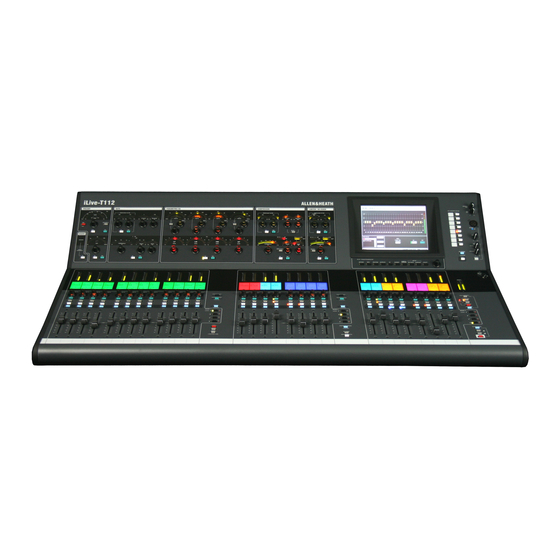
- Page 1 ALLEN&HEATH SERVICE MANUAL iLive-T Copyright © 2009 Allen & Heath Limited. All rights reserved Allen & Heath Limited Kernick Industrial Estate, Penryn, Cornwall, TR10 9LU, UK http://www.allen-heath.com ALLEN&HEATH iLive-T service manual AP7546 issue 8 Page - 1 - of 26...
- Page 2 In certain territories the terms may vary. Check with your ALLEN & HEATH agent for any additional warranty which may apply. For further assistance please contact our distributor or your territory. http://www.allen-heath.com/UK/distributors.asp Release notes for this issue ALLEN&HEATH iLive-T service manual AP7546 issue 8 Page - 2 - of 26...
-
Page 3: Parts Identification
• How to order parts • PCB location & identification • Interior parts SERVICE ACCESS PCB overlays for identification only Note: No schematics are released for this product. VOLTAGE TEST POINTS ALLEN&HEATH iLive-T service manual AP7546 issue 8 Page - 3 - of 26... - Page 4 They are not critical to the basic function of the unit. It is for the owner / service engineer to decide to update a unit with development changes. ALLEN&HEATH iLive-T service manual AP7546 issue 8 Page - 4 - of 26...
- Page 5 Ensure that jumper settings and control configurations are correctly set according to the requirements of the customer. Continued - ALLEN&HEATH iLive-T service manual AP7546 issue 8 Page - 5 - of 26...
-
Page 6: Operation
For effective fault diagnosis trace the signal flow through the circuit path. Refer to the system block diagram. Replacement circuit assemblies are available from Allen & Heath. ALLEN&HEATH iLive-T service manual AP7546 issue 8 Page - 6 - of 26... - Page 7 Black knob Processor inverter AE6466 AJ6387 middle 003-839 80 Processor left 003-837 Touch screen control 003- 544 Touch screen AE6465 Talkback 003-794 TFT mid 003-847 TFT right 003-848 ALLEN&HEATH iLive-T service manual AP7546 issue 8 Page - 7 - of 26...
- Page 8 Bank 003-932 AE7440 003-841 003-543 Channel Channel Channel Channel R expander 003-845 003-846 003-844 003-844 T112 Encoder knob AJ5782 Channel Channel Channel R expander 003-845 003-844 003-846 ALLEN&HEATH iLive-T service manual AP7546 issue 8 Page - 8 - of 26...
- Page 9 5V PCB 003-793 003-323 T112 Bank M Bank R Fader Fader master (4) 003- 003-842 003-843 slave (8) 796 fitted with daughter 003-323 board 5V PCB 003-793 ALLEN&HEATH iLive-T service manual AP7546 issue 8 Page - 9 - of 26...
- Page 10 AJ7887 guide with LED window AJ7888 Guide with NO LED window Knobs. AJ3503 FADER KNOB 11MM BK-WH T AJ5782 KNOB ENCODER LIGHT PIPE AJ6387 KNOB BLACK WITH LINE ALLEN&HEATH iLive-T service manual AP7546 issue 8 Page - 10 - of 26...
- Page 11 Audio PCB. Bottom & top. 80 003-792 003-748 112 003-864 T80 – T112 112 shown. The 80 has fewer audio connectors. Controller 003 791 T80 – T112 ALLEN&HEATH iLive-T service manual AP7546 issue 8 Page - 11 - of 26...
- Page 12 SERVICE ACCESS 1. Remove screws from under arm rest. Arm rest T80 x4 T112 x5 2. Remove screws from base internal bracket. ALLEN&HEATH iLive-T service manual AP7546 issue 8 Page - 12 - of 26...
- Page 13 3. Remove screws from rear panels Rear T80 x4 T112 x5 ALLEN&HEATH iLive-T service manual AP7546 issue 8 Page - 13 - of 26...
- Page 14 4. Note locations of internal harnesses. ALLEN&HEATH iLive-T service manual AP7546 issue 8 Page - 14 - of 26...
- Page 15 5. Disconnect harnesses. 6. Remove side panel screws. Side T80 x5 T112 x5 7. Lift top panel from base. ALLEN&HEATH iLive-T service manual AP7546 issue 8 Page - 15 - of 26...
-
Page 16: Interior Parts
Fan on rear panel AM5020 Fan on PSU AM4959 Audio PCB. Bottom & top. Controller 003-748 PSU 003-790 80 003-792 003 791 112 003-864 Fader power 003-931 T80 – T112 ALLEN&HEATH iLive-T service manual AP7546 issue 8 Page - 16 - of 26... - Page 17 Issue 1, 2 ASSIGN AS T80 OR T112 Issue 3 → ASSIGN AS T80 OR T112 OR R72 iLive controller PCB 003-791 T80 audio PCB 003-792 T80 audio Top ALLEN&HEATH iLive-T service manual AP7546 issue 8 Page - 17 - of 26...
- Page 18 T112 audio PCB 003-864 T112 audio Top T80/112 PSU 003-790 ALLEN&HEATH iLive-T service manual AP7546 issue 8 Page - 18 - of 26...
- Page 19 T80 processor left 003-837 T112 processor left 003-838 ALLEN&HEATH iLive-T service manual AP7546 issue 8 Page - 19 - of 26...
- Page 20 T80/112 processor left 003-839 T112 bank L 003-863 T80 bank L 003-841 ALLEN&HEATH iLive-T service manual AP7546 issue 8 Page - 20 - of 26...
- Page 21 T80/112 bank M 003-842 T80/112 bank R 003-843 T80/112 channel LM channel R ALLEN&HEATH iLive-T service manual AP7546 issue 8 Page - 21 - of 26...
- Page 22 T80/112 channel expander 003-846 T80/112 TFT middle 003-847 T80/112 TFT right 003-848 ALLEN&HEATH iLive-T service manual AP7546 issue 8 Page - 22 - of 26...
- Page 23 T80/112 Fader PSU 003-931 T80/112 Fader master 5V 003-793 T80/112 headphones 003-932 Phantom power for Fan for T112 Fan / phantom power PCB 003-938 ALLEN&HEATH iLive-T service manual AP7546 issue 8 Page - 23 - of 26...
- Page 24 VOLTAGE TEST POINTS Audio PCB Details on next page. ALLEN&HEATH iLive-T service manual AP7546 issue 8 Page - 24 - of 26...
- Page 25 Pre regulated -15V +15V +/-15V resistors ALLEN&HEATH iLive-T service manual AP7546 issue 8 Page - 25 - of 26...
- Page 26 Controller PCB Phantom 3.3V Power ALLEN&HEATH iLive-T service manual AP7546 issue 8 Page - 26 - of 26...
Need help?
Do you have a question about the iLive-T and is the answer not in the manual?
Questions and answers