Table of Contents
Troubleshooting

Related Manuals for Samsung UN43TU7000F


Summary of Contents for Samsung UN43TU7000F
- Page 1 UHD TV Project : UTU7000K Chassis : UWL02 UWL01 Model : UN43TU7000F UN50TU7000F UN55TU7000F SERVICE Manual UHD TV Contents 1. Precautions 2. Product specifications 3. Disassembly and Reassembly 4. Troubleshooting 5. Wiring Diagram UN**TU7000F...
-
Page 2: Table Of Contents
Contents 1. Precautions ..........................1-1 1-1. Safety Precautions ..........................1-1 1-1-1. Warnings ..........................1-1 1-1-2. Servicing the LED TV ......................1-1 1-1-3. Fire and Shock Hazard ......................1-1 1-1-4. Product Safety Notices ......................1-2 1-2. Servicing Precautions ........................1-3 1-2-1. General Servicing Precautions ....................1-3 1-3. - Page 3 4-3. Video Troubleshooting ........................4-4 4-3-1. Customer Picture Test ......................4-4 4-3-2. Video Circuit Layout ......................4-5 4-3-3. Combined MAIN/T-CON Models ..................4-6 4-4. AUDIO Troubleshooting ........................4-9 4-5. Network Troubleshooting ......................4-10 4-5-1. Checking the Internet connection status ..............4-10 4-5-2.
- Page 4 E.Asia, W.Asia, China, Japan https://gspn2.samsungcsportal.com N.America, S.America https://gspn3.samsungcsportal.com This Service Manual is a property of Samsung Electronics Co.,Ltd. © 2020 Samsung Electronics Co.,Ltd. Any unauthorized use of Manual can be punished under applicable All rights reserved. International and/or domestic law.
-
Page 5: Precautions
1. Precautions 1. Precautions 1-1. Safety Precautions Follow these safety, servicing and ESD precautions to prevent damage and to protect against potential hazards such as electrical shock. 1-1-1. Warnings For continued safety, do not attempt to modify the circuit board. Disconnect the AC power and DC power jack before servicing. -
Page 6: Product Safety Notices
1. Precautions 1-1-4. Product Safety Notices Some electrical and mechanical parts have special safetyrelated characteristics which are often not evident from visual inspection. The protection they give may not be obtained by replacing them with components rated for higher voltage, wattage, etc. Parts that have special safety characteristics are identified by on schematics and parts lists. -
Page 7: Servicing Precautions
1. Precautions 1-2. Servicing Precautions An electrolytic capacitor installed with the wrong polarity might explode. WARNING Before servicing units covered by this service manual, read and follow the Safety Precautions section of this manual. CAUTION If unforeseen circumstances create conflict between the following servicing precautions and any of the safety precautions, always follow the safety precautions. -
Page 8: Static Electricity Precautions
1. Precautions 1-3. Static Electricity Precautions Some semiconductor (solid state) devices can be easily damaged by static electricity. Such components are commonly called Electrostatically Sensitive Devices (ESD). Examples of typical ESD are integrated circuits and some field-effect transistors. The following techniques will reduce the incidence of component damage caused by static electricity. 1. -
Page 9: Installation Precautions
1. Precautions 1-4. Installation Precautions 1. For safety reasons, more than a people are required for carrying the product. 2. Keep the power cord away from any heat emitting devices, as a melted covering may cause fire or electric shock. 3. -
Page 10: Product Specifications
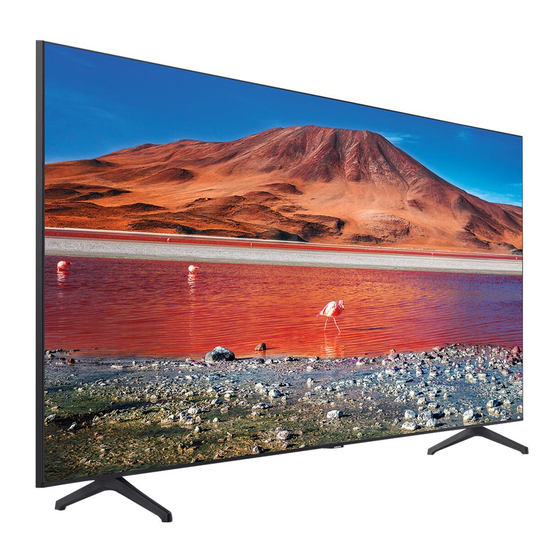
2. Product specifications 2. Product Specifications 2-1. Product Information Model UN**TU7000F Front View * W : Width H : High D : Depth Detail View Color Front : TITAN GRAY / Stand : TITAN GRAY / Deco : CARBON SILVER... -
Page 11: Specifications
2. Product specifications 2-2. Specifications Model Name UN43TU7000 UN50TU7000 UN55TU7000 Display Resolution 3840 x 2160 3840 x 2160 3840 x 2160 Screen Size Diagonal 43˝ Class 50˝ Class 55˝ Class 42.5 inches 49.5 inches 54.6 inches Measured Diagonally Sound (Output) 20 W 20 W 20 W... -
Page 12: Other Information
2. Product specifications 2-3. Other Information NOTE Design and specifications are subject to change without prior notice. Item UN**TU7000FXZA General Product Information Series Country UNITED STATES Cabinet U43TK1 U50TK1 U55TK1 Display Screen Size 43" 50" 55" Diagonal Screen Size 42.5" 49.5"... - Page 13 2. Product specifications Item UN**TU7000FXZA Audio Multiroom Link Blutooth Audio Smart Service Samsung SMART TV Smart Operating System Tizen™ Bixby Far-Field Voice Interaction Multi Voice Assistant Works with Google Assistant Works With Alexa TV Plus Web Browser SmartThings App Support...
- Page 14 2. Product specifications Item UN**TU7000FXZA Connectivity Ethernet (LAN) Audio Out (Mini Jack) Digital Audio Out (Optical) RF In (Terrestrial / Cable input / Satellite 1/1(Common Use for Terrestrial)/0 input) Ex-Link ( RS-232C ) HDMI A / Return Ch. Support eARC HDMI Quick Switch WiFi Yes (WiFi5)
- Page 15 2. Product specifications Item UN**TU7000FXZA Additional Connect Share™ (HDD) Feature ConnectShare™ (USB 2.0) Extended PVR Game Mode Yes (Auto Game Mode) Freesync G-SYNC OSD Language English, Spanish, French BT HID Built-in USB HID Support V-Chip IPv6 Support MBR Support Eco Feature Eco Sensor Power Power Supply...
-
Page 16: Accessories
The part code for some accessories may differ depending on your region. • The provided accessories may vary depending on the model. Holder-Cable Power Cable Samsung Smart Remote / User Manual / Batteries (AAA x 2) Regulatory Guide Product Code. No Product Code. -
Page 17: Key Features & Operation
2. Product specifications 2-5. Key Features & Operation 2-5-1. 2020’ About This TV „ Contact Samsung TV Info – “About This TV” Settings Support About This TV £ £ £ QR CODE (Scanned & processed by email) MN : "Model Number"... -
Page 18: Viewing The Functions
Actual remote control may differ from image shown. • Service may not be launched at the same time as Samsung TV, and the availability may vary by region. 2-6-2. Spend time watching, not searching Universal Guide (Availability of the feature may vary by region. Check before use.) A curated list of content from broadcast and streaming channels, personalized to you. -
Page 19: Just Tap To Mirror
2-6-4. Fits with your home ecosystem Works with Make life more connected. Samsung TV works seamlessly with Amazon Alexa, Google Assistant and AirPlay 2. • Some features and functions provided by connected devices may not be supported or limited to use. -
Page 20: Works Wth Amazon Alexa
2-6-5. Works wth Amazon Alexa Amazon Alexa New Samsung TV works with Alexa so your life just got simpler. It’s easy to connect your Alexa-enabled devices. With Samsung TV's compatibility, have Alexa turn on your TV, change channels, control volume, and more. -
Page 21: Control Your Tv With The Google Assistant
2. Product specifications 2-6-6. Control your TV with the Google Assistant Google Assistant Now Samsung TV works with your Google Assistant to get more done hands-free. Change channels, adjust the volume, control playback and more with just your voice. •... -
Page 22: The Remote Control
2. Product specifications 02 The Remote Control 2-7. The Remote Control About the Buttons on the Remote Control 2-7-1. About the Buttons on the Remote Control • The images, buttons, and functions of the remote control may differ depending on the model. –... -
Page 23: Installing Batteries Into The Remote Control
• The screen may dim if the protective film on the SAMSUNG logo or the bottom of the TV is not removed. Please • The screen may dim if the protective film on the SAMSUNG logo or the bottom of the TV is not removed. -
Page 24: Rear Connect
2. Product specifications 2-9. Rear Connect BACK OF TELEVISION ARRIÈRE DU TÉLÉVISEUR PARTE TRASERA DEL TELEVISOR OPTICAL ANT IN 2-15... -
Page 25: Disassembly And Reassemble
This section of the service manual describes the disassembly and reassembly procedures for the LED TV. 1. Disconnect the LED TV from the power source before disassembly. 2. Follow these directions carefully. - Use the Samsung Service tool to disassemble the cabinet. • Recommend to use the Samsung Service tool CAUTION - Recommended Torque for Cabinet/Stand screws : 10 ~ 12kgf. - Page 26 3. Disassembly and Reassemble Description & Screws Picture Description Insert the Open Jig completely into the tab of the rear cover’s left side bottom corner and Jig Direction following directions 1→2→3. Assembly Misc P-jig-2017 BN81-14946A Locking tabs locations • 43 inches - Top : 8 point - Left/Right : 4 point - Bottom : 6 point...
- Page 27 3. Disassembly and Reassemble Description & Screws Picture Description • 55 inches - Top : 10 point - Left/Right : 4 point - Bottom : 10 point - Cover Raer : 3 point Cover Rear Bottom Lift top side then pull back to remove the back cover.
- Page 28 3. Disassembly and Reassemble Description & Screws Picture Description Remove the Cables. 1CNT • FFC Cables • ASSY SPEAKER P-FRONT Cable • LEAD CONNECTOR-SUB ASSY Cable FFC Cables ASSY SPEAKER P-FRONT Cable LEAD CONNECTOR-SUB ASSY Cable 2CNT FFC Cables ASSY SPEAKER P-FRONT Cable LEAD CONNECTOR-SUB ASSY Cable...
- Page 29 3. Disassembly and Reassemble Description & Screws Picture Description Remove the Integrated Module (BT/WIFI/IR/ LEAD CONNECTOR-SUB ASSY Cable FUNCTION). • LEAD CONNECTOR-SUB ASSY Cable Integrated Module (BT/WIFI/IR/FUNCTION) Remove the ASSY SPEAKER P-FRONT. ASSY SPEAKER P-FRONT Cable • ASSY SPEAKER P-FRONT Cable •...
- Page 30 3. Disassembly and Reassemble Description & Screws Picture Description Before remove ASSY PCB MAIN, Discharge Capacitors 1CNT Before remove 3in1 board, Must discharge capacitors for your safety. Check discharge point(1st, 2nd block) and then, discharge with discharge-Jig. Service Jig-Capacitor Discharge Measurement point • If LED ON £...
- Page 31 3. Disassembly and Reassemble Description & Screws Picture Description Before remove ASSY PCB MAIN, Discharge Capacitors 2CNT Before remove 3in1 board, Must discharge capacitors for your safety. Check discharge point(1st, 2nd block) and then, discharge with discharge-Jig. Measurement point Service Jig-Capacitor Discharge • If LED ON £...
- Page 32 3. Disassembly and Reassemble Description & Screws Picture Description Remove the ASSY PCB MAIN. • Gently lift up (Top Right corner) to release the lock. • Use both hands to hold the board and slide to the left to release the board. NOTE • When installing the Main board, verify the board is properly positioned in all 4...
-
Page 33: Troubleshooting
4. Troubleshooting 4. Troubleshooting 4-1. Power Troubleshooting 4-1-1. FUNCTION/IR Control Test CN11_CM (Main Board Pins) WIFI_DM WIFI_PHY_ON Pin 19 Pin 1 WIFI5V_PW WIFI_DP IR5V_PW Pin 2 Pin 20 WIFI_GND WIFI_WOL IR_GND UART_TX WIFI_NRESET BT_WAKE KEY_INPUT1 KEY_INPUT2 LED_STB_OUT WIFI_GND ECO_SCL_I2C IR_GND ECO_SDA_I2C IR_OUT_1 Function/Wi-Fi/BT... -
Page 34: Function/Ir Control Test Of Function/Wi-Fi /Bt Module
4. Troubleshooting 4-1-2. FUNCTION/IR Control Test of Function/Wi-Fi /BT Module Function Pins USB DM KEY1 USB DP KEY2 I2C_SCL UART_TX I2C_SDA BT_WAKLE_UP DMIC_DATA WIFI_SUSPEND DMIC_CLK WIFI_WAKE_UP RESET IR_LED1 IR_RX IR_LED2 <WCT733M Pin Assignments> Function/Wi-Fi/BT Connector Wi-Fi /BT Pins Function Pins 1 2 3 4 5 6 7 8 9 10 11 12 12 14 15 16 17 18 19 20 LED Status/ Function <... -
Page 35: 3In1/Panel Backlight Test
4. Troubleshooting 4-2. 3IN1/Panel Backlight Test CNL801 (LED Connector) *Only 55 inches CNL801 LED Connector 1. Find LED+/LED- TP point in 3in1 board. 2. Check LED voltage spec in 3in1 board. 3. Using Multi-meter, measurement LED+/LED- TP Point. 4. If Voltage is abnormal, replace 3in1 board. 5. -
Page 36: Video Troubleshooting
4. Troubleshooting 4-3. Video Troubleshooting 4-3-1. Customer Picture Test „ MAIN BOARD Pre-FRC / Post FRC NOT AVAILABLE THIS MODEL (120 Hz / 240 Hz Models Only) Main Section Pre-FRC Post FRC Results Problem Pre-FRC / Post FRC NOT AVAILABLE THIS MODEL (120 Hz / 240 Hz Models Only) •... -
Page 37: Video Circuit Layout
4. Troubleshooting 4-3-2. Video Circuit Layout • ENTER : Factory mode Test Pattern £ £ Main Board KANT-SU2 Scaler Pattern / US Post Pattern T-CON SoC TCON Test Pattern [Factory Mode] „ Check Test Patterns 1. Verify "Scaler Pattern" and "US Post Pattern" 2. -
Page 38: Combined Main/T-Con Models
4. Troubleshooting 4-3-3. Combined MAIN/T-CON Models • Main Section PRE FRC Section POST FRC Section T-CON Section £ PANEL £ £ £ „ Pre Scaller & US Post of Main Section Customer Picture Test 1 Mute > 1 > 4 > 7 > Mute Video Operation Generated on Main Section. - Page 39 4. Troubleshooting „ POST FRC Section Customer Picture Test 3 POST FRC (Factory Mode) Video Operation Generated at Post FRC Section. • If OK: Replace Main Board • If Noisy: Mute £ 3 £ 6 £ 9 £ Mute „ T-CON Section Mute >...
- Page 40 4. Troubleshooting „ PANEL • Check Panel 1. If Noisy Video: Soc T-CON Pattern in Factory Mode → Use type of Noise observed (Bars, single lines, video distortion, etc to help.) → If noise is only on one half of screen check / swap panel cables. →...
-
Page 41: Audio Troubleshooting
4. Troubleshooting 4-4. AUDIO Troubleshooting • Source Main Board Speakers £ £ „ AUDIO TEST • The picture is good but there is no sound. Set Sound Output to TV Speaker. → Settings Sound Sound Output £ £ £ • The speakers are making an odd sound. Run Sound Test. -
Page 42: Network Troubleshooting
4. Troubleshooting 4-5. Network Troubleshooting When the TV has difficulties connecting to the Internet, these steps may help resolve the problem. <TV> <Router> <Internet> 4-5-1. Checking the Internet connection status Settings General Network Network Status £ £ £ £ „ TV to Router "Failure" 1. Select the Network Status menu. – View the current network and Internet status. <Network Status : TV Router Internet>... - Page 43 4. Troubleshooting „ Router to Network "Failure" 1. Select the Network Status menu. – View the current network and Internet status. 2. Check the connection status of your TV and network devices on the Network Status menu. <Network Status : TV Router Internet>...
-
Page 44: Using The Wifi Analyzer App
4. Troubleshooting 4-5-2. Using the Wifi Analyzer App 1. Download the free app from your Android phone called Wi-Fi Analyzer. Wi-Fi Analyzer 2. Select Network under test. 3. Check Signal Strength Meter at both router location and TV location. Check other Wi-Fi Signals in the area. Check for competing adjacent channels. -
Page 45: Wired Lan Operation Test (Tv To Router)
4. Troubleshooting 4-5-3. Wired LAN Operation Test (TV to Router) Settings General Network Network Settings Network Type Wired £ £ £ £ £ £ Use an external Router and LAN Cable for testing. NOTE No Internet connection is required or used in this example. 1. -
Page 46: Know Before Wireless Internet Connection
4. Troubleshooting 4-5-4. Know Before Wireless Internet Connection Wi-Fi Security Key Distance between the wireless router and TV Go to TV Web Browser / Go to speedof.me / testmy.net → HD Video Streaming - 5Mbps and up → UHD Video Streaming - 25Mbps and up →... -
Page 47: Smart Hub
4. Troubleshooting 4-6. Smart Hub When the TV has difficulties connecting to the Internet, these steps may help resolve the problem. <TV> <Router> <Internet> <Samsung Server> 4-6-1. Smart Hub Connection Test Settings Support Device Care Self Diagnosis Smart Hub Connection Test £ £ £ £ £ 1. Select the Smart Hub Connection Test menu. – The Test Smart Hub Connection screen appears. - Page 48 • ISP Blocking If it Fails: → Internet Service Provider is Active. → With DNS setting at 8888. → With Hot Spot. • Samsung Server Test If it Fails: → Network Status. If OK: → Reset Smart Hub. → Terms of Agreement are accepted.
-
Page 49: Bluetooth/Wifi Module
4. Troubleshooting 4-7. BlueTooth/WiFi Module Pin20 Pin1 WCT734M Pin Assignments USB DM KEY1 USB DP KEY2 I2C_SCL UART_TX I2C_SDA BT_WAKLE_UP DMIC_DATA WIFI_SUSPEND DMIC_CLK <FUNCTION/IR/BT/WIFI> WIFI_WAKE_UP RESET IR_LED1 Wi-Fi /BT Pins Function Pins IR_RX IR_LED2 1 2 3 4 5 6 7 8 9 10 11 12 12 14 15 16 17 18 19 20 <... - Page 50 4. Troubleshooting „ About This TV to check Settings Support About This TV £ £ £ Wired MAC Address : missing or error → Replace Main Board Wireless MAC Address Bluetooth Address → If Bluetooth Address or Wireless MAC Address are missing or errors exist. BT &...
-
Page 51: Factory Mode
Factory Remote 1. Power TV ON. 2. Select TV Source. 3. Info → Factory. 4. Use MENU for return. AA81-00243A (Service Remotes) Samsung IR Remote 1. TV Power Standby. 2. Press as follows. • Remote Button NTSC MUTE POWER INFO MENU MUTE... - Page 52 4. Troubleshooting Performing Factory Reset 1. Enter Factory Mode. 2. Select Option Factory Reset £ 3. TV will power off. 4. Perform ALL TV Settings. (New out of box condition) First Screen Appearing in Factory Mode • Sample : UN50TU7000FXZA T-KTSU2AKUC-XXXX.XX Option T-KTSU2INTV-XXXX...
- Page 53 4. Troubleshooting „ Important Screen Info • Micom Version T-KTSU2AKUC-XXXX.XX • Sub Micom T-KTSU2INTV-XXXX T-KTSU2FP-XXXXXXXX.XXXXXXXX TIZEN-ONEMAIN-KantSU2-XXXXXX-RELEASE_XXXXXXXX.X • Tizen Platform info (Debug) • BT Version BT Version : BLUETOOTH-VER-XXXX • E-Manual E-Manual:---- • Blaster Version Blaster Version : Not support E-POP Version : ---- • E-POP Version EDID SUCCESS • EDID Success (Status)
- Page 54 4. Troubleshooting „ SVC £ Test Patterns Main Board KANT-SU2 Scaler Pattern / US Post Pattern T-CON SoC TCON Test Pattern [Factory Mode] IMPORTANT FRC PRE / FRC POST Test Patterns May be available (120 Hz / 240 Hz Models Only) 1.
- Page 55 4. Troubleshooting „ Factory Mode £ Control £ EDID (Restoring HDMI Inputs) 1. Remove ALL HDMI connections. 2. Factory Mode £ Control £ EDID. (→ Enter Key) Option EDID Control Sub Option Debug Hotel Option Shop Option Asia Option ADC/WB Sound Advanced 3.
- Page 56 4. Troubleshooting „ SVC £ Info £ ER Count Check each item listed. „ Important Items WD Count: Watch Dog → Hardware related issue. AR Count: Auto Reset → Software (i.e. Apps) related. WiFi Count: Check all listed items BT Count: Check all listed items VCC Fail Count →...
-
Page 57: Replacing Main Board
4. Troubleshooting 4-9. Replacing Main Board When replacing Main Board, certain values needs to be manually input in Factory menu to complete the replacement. „ Steps to Replace Main Board 1. Enter Factory Menu (Use Factory Remote only). – Power TV on : Select TV Source Info/Factory Option... - Page 58 4. Troubleshooting Writing Type • For Quick Entry of Type. Confirm Type from Option Byte Table for your TV. Home Updates Exit 2. Select Writing Type. Factory Reset "Set Panel Type" appears. Type 50D6AUAGT 4. Enter exact Model Type using cursors. Writing Type 5.
- Page 59 4. Troubleshooting SW Model • Check Label Rating of the TV (located on the Rear Cover). – SW Model is digits after "/" in Version No. – Choose same SW Model code from the list. Home Updates Exit Factory Reset Type 50D6AUAGT Writing Type...
- Page 60 4. Troubleshooting Front Color • Check Label Rating of the TV (located on the Rear Cover). Home Updates Exit Factory Reset Type 50D6AUAGT Writing Type Local Set SW Model UTU7000 Front Color UTU7000K-U50TK1 Writing Front Color Model Code UN50TU7000FXZA TUNER QTQ80D-Q49TD1 QTQ950SA-Q85TA1 QTQ80D-Q55TD1...
- Page 61 4. Troubleshooting Model Code • For Quick Entry of Model Code. Confirm Model Code from Option Byte Table for your TV. Home Updates Exit 2. Select Model Code. Factory Reset "Set Model Code" appears. Type 50D6AUAGT 4. Enter exact Model Code using cursors. Writing Type 5.
-
Page 62: Detail Factory Option
4. Troubleshooting 4-10. Detail Factory Option NOTE If you replace the main board with new one, please change the factory option as well. The options you must change are "Type". „ UN43TU7000FXZA • PANEL / SMPS / MAIN Information PANEL SMPS MAIN Vendor... - Page 63 4. Troubleshooting „ UN50TU7000FXZA • PANEL / SMPS / MAIN Information PANEL SMPS MAIN Vendor Code/Spec Type Vendor Code/Spec ASSY CHASSIS ASSY PCB MAIN BN95-06370D 50D6AUAGT BN91-21840G BN96-50987A DB01 CY-BT050HGNV4H BN95-06726B 50K6AUAGT BN91-21962J BN96-51826A XC02 CY-BT050HGCV2H BN95-06497D 50L6AUAGT BN91-22464R BN96-51369A AB03 CY-BT050HGAV4H • MAIN Factory Option...
- Page 64 4. Troubleshooting „ UN55TU7000FXZA • PANEL / SMPS / MAIN Information PANEL SMPS MAIN Vendor Code/Spec Type Vendor Code/Spec ASSY CHASSIS ASSY PCB MAIN BN95-06372C 55A6AUAGT BN91-21840J BN96-50973A FA01 CY-BT055HGLV3H BN95-06371C 55S6AUAGT BN91-22464U BN96-51370A CA02 CSOT CY-BT055HGHV4H • MAIN Factory Option Local Set BOM Model Front Color...
-
Page 65: Factory Data
4. Troubleshooting 4-11. Factory Data „ Option Factory Menu Name Data Range Factory Reset • Type 50D6AUAGT Refer to "4-10. Detail Factory Option". Writing Type Local set SW Model UTU7000 Front Color Writing Front Color • Model Code UN50TU7000FXZA 43/50/55 •... - Page 66 4. Troubleshooting Factory Menu Name Data Range ECO IC TYPE NOT_DETECT COLOR IC TYPE RISG315 Info Link Server Type development Info Link Country None TTX Group UserOSD OPTION_SWU RF Remocon Support CDD mode … DPMS Support T-CON Device NIKE-L RM Server Type Operating LMF LEAVE THRESHOLD LMF TRIM THRESHOLD...
- Page 67 4. Troubleshooting Factory Menu Name Data Range FirstScreen Cach Size Hotel Option Hospitality Mode Power On Menu OSD Operation Music Mode External Source Eco Solution Cloning Shop Option Exhibition Mode Peak Mode Metadata Shopmode Picture Reset Asia Option Unbalance AF Level adjust TX Power Level Mono Last Memory H Shaking...
- Page 68 4. Troubleshooting Factory Menu Name Data Range Subwoofer Support Woofer Type Woofer Volume 0xc7h Woofer Scale 0x3fh Woofer Check sum 0x0000A273 PEQ Inx PEQ Test Ready Speaker EQ Bottom Checksum NONE Wall Filter Type SRS Tuning Parm SPDIF PCM Gain AudioDock BT Delay 3D_Glass BT delay Mic Scale...
- Page 69 4. Troubleshooting Factory Menu Name Data Range FHD DDR SSC ON OFF FHD DDR SSC Value UHD DDR SSC ON OFF UHD DDR SSC Value P eBus SSC ON/OFF P eBus Value LVDS SSC ON/OFF LVDS SSC Value AP Vx1 SSC ON/OFF AP Vx1 Value N Vx1 SSC ON/OFF N Vx1 Value...
- Page 70 4. Troubleshooting Factory Menu Name Data Range BT_ON_OFF RF Mute Time 600ms Tuner Margin European specifications FRC FDISPLAY ON/OFF 3D FDISPLAY ON/OFF PC Mode ON/OFF FRC VX1 RX EQ SETTING FRC VX1 TX Pre_emphasis setting Netflix OSD Threshold TCON TCON_TEMP READ TEMP LAST 6000 DCC VERSION TCON Demura Bypass...
- Page 71 4. Troubleshooting Factory Menu Name Data Range HDMI SW Failure HDMI Rx Failure MP Failure Main SerDES Failure Jack SerDES Failure Stress Mode Log Analyzer Error Popup On/Off DeadLock KILL CES Option CES Convergence Option CES ATSC 3_0 CES OOBE MVPD SUPPORT BT DUT BT Throughput Reproduce Module...
- Page 72 4. Troubleshooting „ SVC Factory Menu Name Data Range Self Test(for HW) * the Output of test pattern from each IC Info Reset Apps Reset SVC Reset SPI Flash Reset Data Sync Reset Factory Data Reset OPTION_HDMI DVI/HDMI SOUND Auto HDMI HOT PLUG Disable HOTPLUG SWITCHING...
- Page 73 4. Troubleshooting Factory Menu Name Data Range HDMI HDCP EN HDMI HDCP EN FLAG POWER ON FLT CNT LOS HDCP UPDATE SPI READY SPI VERSION HdmiRx EQ HDMI TMDS ERR DET DVB CI TS Clock delay TC TS Clock delay S CI Control Buf ON TS Clock delay CPU TS Clock delay TC2...
- Page 74 4. Troubleshooting Factory Menu Name Data Range PANEL FLASH UPGRADE Logic Usb D/L SUBMICOM UPGRADE * Upgrade Sub-Micom Program SUBMICOM JP USB UPGRADE BT UPGRADE BT FREEPAIRING Function Upgrade FRC3D FW UPGRADE FRC3D SRP UPGRADE FRC3D LD UPGRADE FRC2 3D FW UPGRADE Camera Upgade * Upgarde Camera module(There is upgrade program in Main-Image)
- Page 75 4. Troubleshooting Factory Menu Name Data Range Source Direct On/Off Apps Update Auto Power LAST POWER SMCE Control Motor Test Cube Test V APP Picture Direct On/Off SVC Panel ORIGINAL Serial number Writing S/N „ ADC/WB Factory Menu Name Data Range AV Calibaration Comp Calibration...
- Page 76 4. Troubleshooting Factory Menu Name Data Range G-Offset B-Offset R-Gain G-Gain B-Gain WB-W2_R_Offset WB_W2_B_Offset WB_W2_R_Gain WB_W2_B_Gain WB_N_R_Offset WB_N_B_Offset WB_N_R_Gain WB_N_B_Gain MGA On/Off R1_Gain G1_Gain B1_Gain R2_Gain G2_Gain B2_Gain R3_Gain G3_Gain B3_Gain R4_Gain G4_Gain B4_Gain R5_Gain G5_Gain B5_Gain R6_Gain G6_Gain B6_Gain R7_Gain G7_Gain B7_Gain...
- Page 77 4. Troubleshooting Factory Menu Name Data Range R8_Gain G8_Gain B8_Gain R9_Gain G9_Gain B9_Gain R10_Gain G10_Gain B10_Gain SPI White Balance SPI White Balance On/Off SPI R-Offset SPI G-Offset SPI B-Offset SPI R-Gain SPI G-Gain SPI B-Gain SPI N Rgain SPI N Bgain SPI N Roffset SPI N Boffset SPI W2 Rgain...
-
Page 78: Av Control Tabe
4. Troubleshooting 4-12. AV Control Tabe Control Item Cmd1 Cmd2 Cmd3 Value General Power Power 0x00 0x00 0x00 0x00 0x01 0x02 Volume Direct 0x01 0x00 0x00 (0~100) 0x01 0x00 Down 0x02 0x00 Mute 0x02 0x00 0x00 0x00 Direct 0x04 Continuous 0x03 0x00 0x01... - Page 79 4. Troubleshooting Control Item Cmd1 Cmd2 Cmd3 Value Relax 0x07 PICTURE BackLight(CellLight) 0~20 0x01 0x00 (0~20) Contrast 0~100 0x02 0x00 (0~100) Brightness 0~100 0x03 0x00 (0~100) Sharpness 0~100 0x04 0x00 (0~100) Color 0~10 0x05 0x00 (0~100) Tint 0x06 0x00 (0~100) Advanced Settings Black Tone 0x07...
- Page 80 4. Troubleshooting Control Item Cmd1 Cmd2 Cmd3 Value Yellow 0x03 PICTURE Advanced Settings Color Space Custom Cyan 0x04 Color Magenta 0x05 Color Space Custom 0~100 0x13 0~100 fixed command Color Red Value Color Space Custom 0~100 0x14 0~100 fixed command Color Green Value Color Space Custom 0~100 0x15...
- Page 81 4. Troubleshooting Control Item Cmd1 Cmd2 Cmd3 Value Auto1 0x01 PICTURE Film Mode Auto2 0x02 Cinema 0x03 Smooth Auto Motion Plus 0x06 0x00 Clear 0x01 Standard 0x02 Smooth 0x03 Custom 0x04 Blur Reduction 0x0b 0x01 value fixed command Judder Reduction 0x02 value fixed command LED Clear Motion...
- Page 82 4. Troubleshooting Control Item Cmd1 Cmd2 Cmd3 Value Position2 0x01 PICTURE Screen Adjustment Position Position3 0x02 Position4 0x03 Reset Picture Reset Picture 0x0d 0x0b 0x00 0x00 3D Mode 0x0e 0x0c 0x00 0x00 2D->3D 0x01 Side By Side 0x02 Top Bottom 0x03 Line By Line 0x04...
- Page 83 4. Troubleshooting Control Item Cmd1 Cmd2 Cmd3 Value Sound_ 0x04 0x00 fixed command Select_Main PICTURE Pip Sound_ 0x01 fixed command Select_Sub Channel_Up 0x05 0x00 fixed command Channel_ 0x01 fixed command Down Sound Sound Mode Standard 0x0c 0x00 0x00 0x00 Music 0x01 Movie 0x02 Clear Voice 0x03 Amplify 0x04...
- Page 84 4. Troubleshooting Control Item Cmd1 Cmd2 Cmd3 Value 0x01 Medium 0x02 High 0x03 Sound TV Installation Type Stand 0x0c 0x00 0x00 Wallmount 0x01 Audio Delay Dealy Value 0~250 0x0d 0x00 (0~250) (0x00~0xFA) Key Generation *Refer for 0x0d 0x00 0x00 Table Show/Hide Control Show 0x0e...
-
Page 85: Updating The Tv's Software
TV to update. To update using a USB device, download the update package from Samsung.com to your computer. Then, save the update package in the USB device's top-level folder. Otherwise, the TV will not be able to locate the update package. -
Page 86: Updating To The Latest Tv Software
4. Troubleshooting 4-13-1. Updating to the latest TV software Updating the Software Updating the Software If you want to keep the TV in its best condition, or if you have an intermittent issue, please update it to the latest version. If you want to keep the TV in its best condition, or if you have an intermittent issue, please update it to the latest If you want to keep the TV in its best condition, or if you have an intermittent issue, please update it to the latest The color and design of the TV and its accessories and the features of the TV may differ depending on the model or geographical... - Page 87 Settings Support About This TV and check the model code and software version. 7. Using a computer, connect to www.samsung.com. - 194 - Using a computer, connect to www.samsung.com. Using a computer, connect to www.samsung.com. Using a computer, connect to www.samsung.com.
- Page 88 4. Troubleshooting 8. Find your TV model and download the firmware file. Find your TV model and download the firmware file. Find your TV model and download the firmware file. Find your TV model and download the firmware file. 9. Find your TV model and download the firmware file. SEE ALL SUPPORT SEE ALL SUPPORT SEE ALL SUPPORT Find your TV model and download the firmware file.
- Page 89 4. Troubleshooting Unzip the downloaded file and store it in your USB drive top folder. Unzip the downloaded file and store it in your USB drive top folder. Unzip the downloaded file and store it in your USB drive top folder. 12.
- Page 90 4. Troubleshooting The firmware update begins automatically. Your TV will automatically powercycle when the firmware update is 15. After your TV turns on, select Settings Support About This TV and check the new firmware version. completed. Do not turn off your TV while the firmware update is in progress. £...
-
Page 91: Wiring Diagram
5. Wiring Diagram 5. Wiring Diagram 5-1. Wiring Diagram • 1 CNT Models MAIN CN1300 PANEL CNL801 CN11_CM CON2 SPEAKER SPEAKER FUNCTION/IR/BT/WIFI • 1 CNT Models_inner... - Page 92 5. Wiring Diagram • 2 CNT Models CN1301_UT2 MAIN CN1300 PANEL CNL801 CN11_CM CON2 SPEAKER SPEAKER FUNCTION/IR/BT/WIFI • 2 CNT Models_inner 5-2...
-
Page 93: Connector
5. Wiring Diagram 5-2. Connector 5-2-1. 3IN1 Board 1 C N302 (5Pin) *2 CNT Models (OPTICAL) 0 C N1301-UT2 2 C N1402 (96Pin) (4Pin) (USIT-RIGHT) (USB) FFC CABLE 3 C N1902 (8Pin) (LAN) 4 C N1703 (19Pin) (HDMI2) 9 C N1300 (96Pin) 5 C N1702 (USIT-LEFT) - Page 94 5. Wiring Diagram „ Main Board Pin Map CN302 (OPTICAL) CN11_CM (FUNCTION/IR/BT/WIFI) SPDIF_OUT B5V_PW WIFI_DM WIFI_PHY_ON WIFI5V_PW DGND IDENT_SPDIF WIFI_DP IR5V_PW DGND WIFI_GND WIFI_WOL IR_GND CN1402 (USB) UART_TX WIFI_NRESET A5V_USB_PW BT_WAKE KEY_INPUT1 KEY_INPUT2 LED_STB_OUT CN1902_LAN WIFI_GND LAN_TXD+_LAN ECO_SCL_I2C IR_GND LAN_TXD-_LAN LAN_RXD+_LAN ECO_SDA_I2C IR_OUT_1...
- Page 95 5. Wiring Diagram CN1300 (USIT LEFT) FB_TRDY_1 Panel 3.3V Panel 3.3V FB_VCOM1_2_CELL VCOM1_CELL VCOM2_CELL VCOM3_CELL VSS_OUT1_CELL,VOFF_- VOFF_-11V_PW VGHD_30V_PW CKV1_GOA 11V_PW CKV2_GOA CKV3_GOA CKV4_GOA CKVB1_GOA CKVB2_GOA CKVB3_GOA CKVB4_GOA STVP1_GOA LC1_VGP1_GOA ST_GOA DEMURA_CS_SPI DEMURA_CLK_SPI DEMURA_HOLD_SPI DEMURA_WP_SPI DEMURA_DI_SPI DEMURA_DO_SPI DEMURA_CS_SPI SFC2 GND(PBFE) USIT8+ USIT8- USIT9+ USIT9- USIT10+ USIT10-...
- Page 96 5. Wiring Diagram *2 CNT Models CN1301_UT2 (USIT-RIGHT) FB_TRDY_2 AVDD_17V_PW AVDD_17V_PW AVDD_17V_PW AVDD_17V_PW UH_CELL UL_CELL HAVDD_8.5V_PW LH_CELL LL_CELL VCCB_1.8V_PW VCCA_1.9V_PW PI_DSF_MON PORTNUM SFC1 USIT0+ USIT0- USIT1+ USIT1- USIT2+ USIT2- USIT3+ USIT3- USIT4+ USIT4- USIT5+ USIT5- USIT6+ USIT6- USIT7+ USIT7- SFC2 GND(P802) ST_GOA LC1_VGP1_GOA...
-
Page 97: Cables
5. Wiring Diagram 5-3. Cables • 1 CNT Models MAIN (96P) FFC CABLE CN1300 PANEL CNL801 CN11_CM CON2 (20P) LEAD CONNECTOR-SUB ASSY SPEAKER SPEAKER FUNCTION/IR/BT/WIFI Part Name & Connection Part Spec Code No. 96P/350 43" BN96-39821C FFC CABLE (L) 50" MAIN - Source B 96P/400 BN96-39891B 55"... - Page 98 5. Wiring Diagram • 2 CNT Models (96P) CN1301_UT2 FFC CABLE MAIN (96P) FFC CABLE CN1300 PANEL CNL801 CN11_CM CON2 (20P) LEAD CONNECTOR-SUB ASSY SPEAKER SPEAKER FUNCTION/IR/BT/WIFI Part Name & Connection Part Spec Code No. FFC CABLE (R) 96P/L600 55" BN96-39823B MAIN - Source B FFC CABLE (L) 96P/L400 55"...