
Related Manuals for Laversab ARTS 7000


Summary of Contents for Laversab ARTS 7000
- Page 1 ARTS 7000 User Manual Aviation Systems Avionics Radio Test Set 7000 (ARTS 7000) Date: 10 November 2021 Rev A6 Page 1...
-
Page 2: Warranty
Laversab catalogues or incorporated in Laversab products in essentially the same form as supplied by the original manufacturer. Warranties of the original manufacturers supplant the warranty of Laversab Inc., but, in applicable instances, the latter agrees to use its best efforts to have original suppliers make good their warranties. -
Page 3: Revision History
ARTS 7000 User Manual Aviation Systems EVISION ISTORY Document No. Release Date Description 125-9120A1 27 Jul 2020 ARTS-7000 User Manual Rev A1 125-9120A2 31 Aug 2020 ARTS-7000 User Manual Rev A2 125-9120A3 19 Nov 2020 ARTS-7000 User Manual Rev A3... -
Page 4: Warning
ARTS 7000 User Manual Aviation Systems WARNING THE ARTS 7000 USES LINE VOLTAGES AND RADIO FREQUENCY SIGNALS FOR ITS OPERATION WHICH ARE POTENTIALLY DANGEROUS. IMPROPER OPERATION OF THIS EQUIPMENT MAY RESULT IN PERSONAL INJURY OR LOSS OF LIFE. HENCE THE EQUIPMENT DESCRIBED IN THIS MANUAL SHOULD BE OPERATED ONLY BY PERSONNEL TRAINED IN PROCEDURES THAT WILL ASSURE SAFETY TO THEMSELVES, TO OTHERS AND TO THE EQUIPMENT. -
Page 5: Table Of Contents
Subsection 1: Test Controller Application Software Update ................33 Subsection 2: ARTS 7000 Firmware Update ...................... 33 Section 6: ARTS 7000 Test Set Hardware Controls & Connections ..............39 Subsection 1: ARTS 7000 Test Set Hardware, Controls & Connections ............. 39 Subsection 2: Hardware &... - Page 6 ARTS 7000 User Manual Aviation Systems Subsection 2: ILS Test Control and Operation Details ..................59 Subsection 3: ILS Test Operation Active Test Control and Indicators ..............61 Section 9: Marker Beacon (Mkr) Operation ......................63 Subsection 1: Mkr Beacon Operation ........................ 63 Subsection 2: Mkr Test Control Details ......................
- Page 7 ARTS 7000 User Manual Aviation Systems Subsection 3: MODE S Results screen ......................133 Section 19: ADSB OUT ............................143 Subsection 1: ADSB Out Operation ........................143 Subsection 2: ADSB Out Test Guide ......................... 144 Subsection 3: ADSB Out Results screen ......................148 Section 20: ADSB IN ..............................
-
Page 8: Notes On This Document
Aviation Systems OTES ON THIS DOCUMENT This document is intended to be a guide to the normal operation of the ARTS 7000 Test System. This manual will explain the technical specifications, features and functions of the ARTS 7000. It has been written as a user reference for the test set operator. It does not detail any specific test procedure or process for any aircraft or aircraft system. -
Page 9: Section 1: Introduction
• Commercial off the shelf tablet control of the test set • Wi-Fi Control from tablet controller to ARTS 7000 test set using a unique ARTS 7000 self-generated Wi-Fi Network. • Tablet operator interface has been specifically designed to be very simple and intuitive to learn and use, yet powerful and customizable to allow extensive detailed testing. -
Page 10: Subsection 3: Key Capabilities
UBSECTION APABILITIES Capability of the ARTS 7000 is defined by which modules are fitted to the test set. There are 3 standard configurations: Nav/Com only, Pulse only, or Nav/Com and Pulse. The following identifies the capabilities by module and technology group. -
Page 11: Subsection 4: Key Features
ARTS 7000 User Manual Aviation Systems ARTS 7000 Key Configuration/Capability Chart Communication Navigation Transponder ARTS 7000 Configuration/ Capability Nav/Com Module Only Pulse Module Only Nav/Com Pulse Modules 4: K UBSECTION EATURES All accessories are included with the standard test system. -
Page 12: Section 2: Controller & User Interface
ONTROLLER PPLICATION The ARTS 7000 test system uses a commercial off the shelf tablet as a controller. The ARTS 7000 test set tablet controller is connected over a Wi-Fi network. This Wi-Fi network is generated by the ARTS test set and does not need to be connected to another network in order to operate. - Page 13 Allows top level user to limit changes to the functions by the operating Preferences technician. Engineering Settings to enable Debugging, Diagnostics, and Analytics tools within the Mode ARTS. Documentation Menu Menu Item Action / Function User manual Opens a condensed version of the ARTS 7000 Operator’s Manual Rev A6 Page 13...
- Page 14 A quick reference to all of the accessories and spare parts that may be Spare Parts required during field operations Support Provides details and contacts for Laversab worldwide support network. Provides Link to Online Training – Test Control Tablet must be connected Training Video to the Internet.
- Page 15 ARTS 7000 User Manual Aviation Systems COM Menu Selects the Com Amplitude Modulation (AM) capability test page. Selects the Com Frequency Modulation (FM) capability test page. HF SSB Selects the COM High Frequency SSB capability test page. SelCal Selects the SELCAL capability test page.
- Page 16 ARTS 7000 User Manual Aviation Systems ELT Menu Selects the Emergency Location Transmitter capability test page. 121.5 MHz, 243MHz and 406 MHz DME Menu Selects the Distance Measuring capability test page. Selects the DME and combined ILS capability test page. This ILS &...
- Page 17 Selects the Mode ADSB Out Test Functions – ADSB Out generated from the aircraft under test. ADSB Selects the Mode ADSB In Test Functions – ADSB IN generated from the ARTS 7000 to the aircraft under test. (Under development) Rev A6...
- Page 18 ARTS 7000 User Manual Aviation Systems Mode S Menu Mode S MODE S Generic Selects the Mode S Generic Test Page. Mode S Selects the Mode S test for a class A Transponder. Class A Mode S Selects the Basic Mode S test for a class B Transponder.
- Page 19 TCAS TCAS Selects the TCAS capability test page. TCAS1, TCAS 2, ACAS Selects the TIS capability test page. (Under Development) Altitude Monitoring Menu Altitude Selects the Altitude Monitoring page to control Laversab ADTS (Under Development) Monitoring Rev A6 Page 19...
-
Page 20: Section 3: Arts 7000 Test Control Application
I CONNECTION AND PPLICATION TART 1. Set up the ARTS 7000 test system on level ground or bench top making sure there are no hazards that may damage the test system or harm the operator. 2. Apply power to the ARTS 7000. - Page 21 ARTS-XXXXX where XXXXX is the serial number of the ARTS 7000 10. Select the ARTS 7000 Wi-Fi and establish a connection. 11. Once ARTS 7000 Wi-Fi Network is connected and stable navigate to the home page of the tablet. 12. On the tablet select the ARTS 7000 application and open the application.
- Page 22 ARTS 7000 User Manual Aviation Systems Rev A6 Page 22...
-
Page 23: Subsection 3: Generic Controls And Indicators
ARTS 7000 User Manual Aviation Systems 3: G UBSECTION ENERIC ONTROLS AND NDICATORS There are some key features to the application that are available on all screens. These are defined below: Item Description Exit Button takes the user back to the previous menu page. - Page 24 ARTS 7000 User Manual Aviation Systems Quick link to the In-App relevant page in the Quick Start Manual. Quick link to the In-App Condensed Training Manual . Indicator for active RF transmission. Only active during a test. Green indicates that active RF signals are being transmitted from the ARTS.
-
Page 25: Section 4: Arts 7000 Test Control Application Menus
On the application Main Menu there are 3 options: Test Functions, Utilities and Documentation. Test Functions contain the individual test capabilities of the ARTS 7000. These items are described in this manual in the individual sections relevant to the capability. The Utilities and... -
Page 26: Subsection 1: The Utilities Menu
ARTS 7000 User Manual Aviation Systems 1: T UBSECTION TILITIES Software Selecting the Software button displays the software revisions page. When the Test Control Tablet is not connected to the ARTS this page will only display the Test Control Tablet application version. - Page 27 With ARTS 7000 connected, the software page displays all installed software including the APP and the software installed on the Nav/Com and Pulse Modules. ARTS 7000 connected. To update the software installed on the ARTS 7000 please refer to the section on Software Updates. Records Menu and Records Export Whenever the ARTS 7000 completes a test, and the capability has results that can be stored, they are accessible on this page.
- Page 28 SMS or Email. Cable/Ant Loss For the ARTS 7000 to make accurate measurements, the losses of the cables and antenna that are used in the test must be taken into account. The Cable/Ant Loss page is the central point to store this information.
- Page 29 The Permissions page allows operators to view, add, and remove licenses related to the ARTS 7000 they may have purchased. Each license is tied to the Serial Number of the ARTS 7000 unit. Users can contact Laversab to add licenses as desired.
- Page 30 ARTS 7000 User Manual Aviation Systems User Preferences Screen Engineering Mode: Enables Engineering mode for troubleshooting the ARTS 7000 test system. When Engineering Mode is ‘On’, the Engineering Mode menu can be accessed in Utilities > Engineering Mode. Engineering Mode Screen...
-
Page 31: Subsection 2: Documentation Menu
• Engineering Debug: When enabled the ARTS will 7000 will record all activity of the test set and save it to an encrypted file that can be sent to Laversab for review. • App Diagnostics: When enabled the system will monitor and record all activity in the application. - Page 32 User Manual: Displays the latest version of the user manual of the ARTS 7000. Spare Parts: Displays a list of key Spare parts & Accessories that are used with the ARTS 7000. Part numbers are included so ordering spares from Laversab is simplified.
-
Page 33: Section 5: Arts 7000 Software Updates
Application Software has been installed. 2: ARTS 7000 F UBSECTION IRMWARE PDATE WARNING When updating the software in the ARTS 7000 it is imperative to use an AC power source during the following procedure. Items required: • ARTS 7000 Test System •... - Page 34 2. Power ON the ARTS 7000 (if necessary) Connect the ARTS 7000 to an AC power outlet. Select AC power on the top panel of the ARTS 7000 and switch ON the ARTS 7000. 3. Power ON and set up the iPad Controller (if necessary).
- Page 35 The iPad now displays the ARTS Versions screen and displays the current software build of the ARTS 7000. This may take a few moments. (It is recommended to take a screen shot of this page to keep a record of the current software build state.
- Page 36 ARTS 7000 User Manual Aviation Systems 5. Update procedure IMPORTANT: We highly recommend that the unit is connected to AC power and battery, it must be ON throughout the entire process. A failure while updating can cause a programming corruption that could damage the unit. The USB must be connected during the process and must not be removed at any time until the update is complete.
- Page 37 ARTS 7000 User Manual Aviation Systems c. Press Start to begin the Software upload. Please note: this process can take up to 10 minutes. d. During the upload the iPad screen will show the following updating screen and progress screen:...
- Page 38 Close the iPad ARTS 7000 application. c. Power down the ARTS 7000. d. Remove the USB drive from the USB slot on the Nav/Com Module. e. The ARTS 7000 system can now be used as normal. Rev A6 Page 38...
-
Page 39: Section 6: Arts 7000 Test Set Hardware Controls & Connections
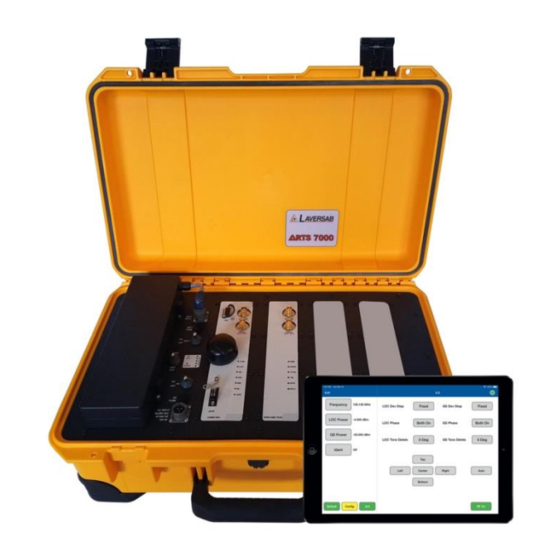
Test Set Dimensions: Approximate dimensions – ARTS 7000 main test set case measures 22” x 14” x 9” and weighs 30 lbs or 56cm x 36cm x 23cm and weighs 14 kg. Weight dependent on configuration. - Page 40 ARTS 7000 User Manual Aviation Systems ARTS 7000 Test Set Top Panel Item Description Battery – Removable battery Power Switches and Connections – Power control Nav/Com Module – Used for all Navigation and Communication functions. Pulse Module – Used for all Pulse (Transponder/DME/TCAS) functions Expansion Slot –...
- Page 41 Unit Power Switch – Main Power switch for setting the unit On - Off Power LED Indicator Panel • Unit: Lit when the ARTS 7000 is on and active. • Power: Lit when the ARTS 7000 is has a suitable power source available •...
- Page 42 Used for connecting the ARTS 7000 Test Antenna for over the air testing. Cable Connection (100W Maximum): Used for Direct /Cable connection between the ARTS 7000 Test Set and a radio or antenna feeder. Wi-Fi Antenna GPS Antenna COM LED Indicator: Lit during an active COM test.
- Page 43 ARTS 7000 User Manual Aviation Systems Pulse Module Item Description Antenna connection (1W Maximum): Used for connecting the Test Antenna for over-the-air testing. Cable Connection (100W Maximum): Used for Direct /Cable connecting the test set directly to a radio or to antenna feeder.
- Page 44 Antenna Mounting Tripod. Used to mount the Pulse antenna but can also be used to mount the Nav/Com antenna remotely from the 118-2286 ARTS 7000 Test Set using the supplied Mounting adapter. Removable Battery 115-1282 External Battery Charger 115-1304...
- Page 45 ARTS 7000 User Manual Aviation Systems Nav Com Antenna 1. NAV/COM Telescopic Antenna 2. Telescopic 3. NAV/Com Telescopic in operation on an ARTS 7000 Antenna Antenna tripod mouting Test Set adater Item Description Part Number 1 & 2 Telescopic Antenna for all Nav Com Functions.
- Page 46 The Pulse antenna is designed to be highly directional and as such, careful alignment between the ARTS 7000 Pulse antenna and the aircraft system under test antenna is required. NOTE the front of the antenna that should be directed to the antenna under test is the side embossed with the Laversab name and Logo.
- Page 47 India Power Cable (6 Feet) 129-1260 vi. China Power Cable (6 Feet) 129-1425 vii. Australia Power Cable (6 Feet) 129-1440 vii. 123-0235 External Attenuator Shown Note: Not all items will be included, unless specifically ordered from Laversab. Rev A6 Page 47...
-
Page 48: Subsection 2: Hardware & Antenna Test Configuration
ARTS 7000 User Manual Aviation Systems 2: H & A UBSECTION ARDWARE NTENNA ONFIGURATION Antenna and Cable configurations by capability Antenna to Antenna Direct Applicable ARTS 7000 Applicable Over-the- Cable Version Cable Connection Test connection Function Optional Antenna 131-0342A1 Attenuator... -
Page 49: Subsection 3: Direct Connections And Antenna Set Up
2. Align the center of the Pulse Antenna as accurately as to the antenna under test. Accuracy is required in both the horizontal and vertical plane. 3. A clear line of sight is required between the antenna under test and the ARTS 7000 a pulse antenna. - Page 50 Antenna Alignment Tool The ARTS 7000 Application includes an Antenna alignment Tool. This software tool is run automatically when it is required for the test application for example during Mode S testing. The alignment tool gives an active antenna connection to the aircraft under test and indicates % replies and ERP.
- Page 51 ARTS 7000 User Manual Aviation Systems All capabilities Direct connection For Direct connection testing. ARTS 7000 Cable connected to an antenna feeder or Unit under test connector. 1. For Nav Com direct connection testing - connect the selected cable from the supplied cables and connect it to the Direct Connection on the Nav/Com module.
-
Page 52: Section 7: Antenna Coupler
OUPLER ESCRIPTION Whenever the ARTS 7000 is used to test transponder or DME systems it is highly recommended to utilize the Laversab Antenna Coupler. The coupler is designed to clamp onto most shark fin style antennas. It can be used on Top or Bottom antennas. Correct placement of the coupler is essential to make sure there is no transmission leak. - Page 53 ARTS 7000 User Manual Aviation Systems Coupler in position on the bottom antenna. In this case the coupler is being used as a shield – note the termination is connected on the coupler connector. The coupler can be used in 2 modes: 1.
-
Page 54: Subsection 2: Antenna Coupler Setup And Operation
Coupler Set-Up 1. Select a suitable cable for connection from the ARTS to the coupler. 2. Connect a 10dB attenuator to the Cable Port of the ARTS 7000 test set. 3. Connect the cable between the Coupler and the 10dB attenuator. -
Page 55: Section 8: Integrated Landing System (Ils) Operation
CONFIG button to establish the user preferences. The ARTS 7000 stores the last configuration used and has a default setting. When the DEFAULT button on the test screen is pressed the ARTS 7000 automatically sets the default mode and settings. - Page 56 Preset (Laversab defined) Channel (Standard ILS LOC Loc Frequency (Preset/Channel frequencies) or Variable. /Variable) See: Appendix C for Laversab Test Default and Preset Frequency Settings Allows the selection of the test power units for the LOC Power (dBm/mV/uV) Localizer. Selections are dBm, mV, uV.
- Page 57 During the active test operation fine adjust is available see below. Sets the ARTS 7000 output power of the Localizer signal. During the active test operation fine adjust is available see below. Sets the ARTS 7000 output power of the Glide Slope signal.
- Page 58 ARTS 7000 User Manual Aviation Systems Selects the Audio Identification transmission from the ARTS 7000. Options are: Off, Tone (1KHz steady tone) or Code (Morse - LSB). When Code is selected the repetition rate is set at 30 seconds. The user can trigger an immediate Code transmission by pressing the code button.
-
Page 59: Subsection 2: Ils Test Control And Operation Details
ONTROL AND PERATION ETAILS 1. Freq. LOC: Sets the frequency of the ARTS 7000 generated Localizer. Automatically sets the linked ARTS 7000 Glide Slope frequency. a. Note: when the test is running the Frequency can be course and fine-tuned to allow selectivity testing. - Page 60 Frequency. Pop up for Sensitivity testing. 4. Power GS: Sets the power of the ARTS 7000 generated Glide Slope signal. a. Note: when the test is running the Frequency can be course and fine-tuned to allow selectivity testing. This done by pushing the Frequency numerical field. A pop up is then displayed to allow live course and fine adjustment of the transmitted frequency.
-
Page 61: Subsection 3: Ils Test Operation Active Test Control And Indicators
ARTS 7000 User Manual Aviation Systems Pop up for Sensitivity testing. 5. Ident: Allows the use to select the audio identifier of the ARTS 7000 generated ILS signal. Possible Selections are: a. Off – No Audio Ident b. Code – the ARTS 7000 generates a repetitive Morse code identification signal comprising the letters LSB. - Page 62 Glide Slope is moved across its range. 7. AUTO: when the Auto function is enabled the ARTS 7000 sets up Localizer and Glideslope signals IAW the preset Frequencies and Power. The ILS signal from the ARTS 7000 then imitates a corkscrew-type motion of the Localizer and Glideslope.
-
Page 63: Section 9: Marker Beacon (Mkr) Operation
CONFIG button to establish the user preferences. The ARTS 7000 stores the last configuration used and has a default setting. When the DEFAULT button on the test screen is pressed the ARTS 7000 automatically sets the default mode and settings. - Page 64 ARTS 7000 User Manual Aviation Systems Mkr Configuration Screen Mkr Configuration Controls and Selections Item Description Selects the over the air (Antenna) connection Port or Port Selection (Cable/Antenna) the Direct (Cable) Connection Port. Allows the selection of the test power units for the Mkr Power (dBm/mV/uV) Beacon.
- Page 65 Sets Mkr Frequency. Fixed at 75 MHz. During the active test operation fine adjust is available see below. Sets the ARTS 7000 output power of the Mkr Beacon signal. During the active test operation fine adjust is available see below.
-
Page 66: Subsection 2: Mkr Test Control Details
UBSECTION ONTROL ETAILS 1. Frequency: Sets the frequency of the ARTS 7000 generated Marker Beacon frequency. This frequency is adjustable from 72.0MHZ to 78.0MHz. 75MHz being the standard frequency. a. Note: when the test is running the Frequency can be course and fine-tuned to allow selectivity testing. - Page 67 ARTS 7000 User Manual Aviation Systems 3. Modulation: Sets the modulation depth of the ARTS 7000 generated Marker Beacon Signal. 4. Outer 400Hz: When the test is running this button is used to toggle the Outer Marker signal on and off. When the Outer Marker signal is active the button will be highlighted in Blue 5.
-
Page 68: Section 10: Ils And Mkr Operation
7000 to antenna connection. Coax Cable Ant – Ant Ant - Ant Optional – Only required for option of 6, 20 or remote ARTS 7000 to antenna connection. 60 ft VARIOUS Dir - Cbl – operator choice of length Direct Cable recommended to use shortest possible. - Page 69 ARTS 7000 User Manual Aviation Systems ILS & Mkr Test Screen ILS & Mkr Test Controls and Selections Item Description Selects the ILS Test Screen. This allows any configuration changes or test attributes to be set for the ILS portion of the test. Exiting from the ILS test screen returns the user to the ILS &...
-
Page 70: Subsection 2: Mkr Test Control Details
ARTS 7000 User Manual Aviation Systems Used to select and toggle the active Inner 3000Hz Marker signal. Indicates the active Signal when highlighted with the color White. This indicator shows the active selected Localizer deviation. This indicator shows the active selected Glide Slope deviation. -
Page 71: Section 11: Vhf Omnidirectional Ranging (Vor) Operation
CONFIG button to establish the user preferences. The ARTS 7000 stores the last configuration used and has a default setting. When the DEFAULT button on the test screen is pressed the ARTS 7000 automatically sets the default mode and settings. - Page 72 Port Selection (Cable/Antenna) the Direct (Cable) Connection Port. Allows the selection of the test VOR Frequency. Frequency Selections are Preset (Laversab defined), Channel (Preset/Channel/Variable) (Standard VOR frequencies) or Variable. Allows the selection of the test power units for the VOR Signal.
- Page 73 Sets Frequency of the ARTS 7000 Generated VOR signal During the active test operation fine adjust is available see below. Sets the output power of the ARTS 7000 generated VOR signal. During the active test operation fine adjust is available see below.
- Page 74 Allows adjustment of the modulation of the 9960Hz sub carrier Modulation Depth Indicates the current bearing of the VOR signal being transmitted from the ARTS 7000. Under normal test condition the aircraft display should show this bearing. Steps the VOR Bearing anti clockwise 1 Step. Each step size is selected from the Config Page.
-
Page 75: Subsection 2: Vor Test Control Details
ONTROL ETAILS 1. Frequency: Sets the frequency of the ARTS 7000 generated VOR frequency. a. Note: when the test is running the Frequency can be course and fine-tuned to allow selectivity testing. This done by pushing the Frequency numerical field. A pop up is then displayed to allow live course and fine adjustment of the Transmitted Frequency. - Page 76 9. AUTO – when the Auto function is enabled the ARTS 7000 sets up a VOR signal IAW the selected frequencies, Power Modulation and Ident. The VOR signal from the ARTS 7000 then automatically steps the bearing in the selected step range from 0 Degrees to 360 Degrees.
-
Page 77: Section 12: Vhf Com Amplitude Modulation (Am)
CONFIG button to establish the user preferences. The ARTS 7000 stores the last configuration used and has a default setting. When the DEFAULT button on the test screen is pressed the ARTS 7000 automatically sets the default mode and settings. - Page 78 Port Selection (Cable/Antenna) the Direct (Cable) Connection Port. Allows the selection of the test Com AM Frequency. Frequency Selections are Preset (Laversab defined), Channel (Preset/Channel/Variable) (Standard Com AM frequencies) or Variable. Allows the selection of the test power units for the Com AM Signal.
- Page 79 ARTS 7000 User Manual Aviation Systems COM AM Test Screens Please note: the test screens differ between the main set up page, Transmit mode and Receive mode. Main test screen and Screen during TX (Transmit) Test Screen during Receive (RX) Mode...
- Page 80 Code button is pushed the ARTS will immediately transmit the Code signal. Toggles the ARTS 7000 from Receive to Transmit mode. On Start up the ARTS 7000 is always in Receive mode. Press this button for Transmit. During an active test this field will indicate the Frequency Transmitted Frequency from the Aircraft.
-
Page 81: Subsection 2: Com Am Test Control Details
Pop up for Sensitivity testing. 3. Modulation: Allows adjustment of the master modulation depth of the of the COM AM signal. 4. Ident: Allows the use to select the audio identifier of the ARTS 7000 generated ILS signal. Possible Selections are: Rev A6... -
Page 82: Subsection 3: Diagnostic Tools
3. Tone – the ARTS 7000 generates a constant 1 kHz audio tone. 5. Frequency (indicator): Indication of the received frequency from the Aircraft transceiver. This field is only active when the ARTS 7000 is in receive mode and receives a signal from the aircraft when PTT is active. - Page 83 ARTS 7000 User Manual Aviation Systems 2. If the received frequency is stable, this will be useful for comparison. If the Aircraft Radio is good the counter frequency and test page frequency should match. 3. If the counter frequency is more than +/-10KHz from the main test frequency, the main test frequency will not be displayed.
-
Page 84: Section 13: Vhf Com Frequency Modulation (Fm)
CONFIG button to establish the user preferences. The ARTS 7000 stores the last configuration used and has a default setting. When the DEFAULT button on the test screen is pressed the ARTS 7000 automatically sets the default mode and settings. - Page 85 Port Selection (Cable/Antenna) the Direct (Cable) Connection Port. Allows the selection of the test COM FM Frequency. Frequency Selections are Preset (Laversab defined), Channel (Preset/Channel/Variable) (Standard COM FM frequencies) or Variable. Allows the selection of the test power units for the COM FM Signal.
- Page 86 ARTS 7000 User Manual Aviation Systems Com FM Test Screens Please note: the test screens differ between the main set up page, Transmit mode and Receive mode. Com FM Main Test Screen And Screen during TX (Transmit) Com FM Test Screen in Receive Mode...
- Page 87 Code signal. Toggles the ARTS 7000 from Receive to Transmit mode. On Start up the ARTS 7000 is always in Receive mode. Press this button for Transmit or Receive. During an active test this field will indicate the Transmitted Frequency from the Aircraft.
-
Page 88: Subsection 2: Com Fm Test Control Details
Pop up control for Sensitivity testing 3. Deviation: Allows adjustment of the frequency deviation of the of the COM FM signal. 4. Ident: Allows the use to select the audio identifier of the ARTS 7000 generated ILS signal. Possible Selections are: 4. - Page 89 6. Tone – the ARTS 7000 generates a constant 1 kHz audio tone. 5. Frequency (indicator): Indication of the received frequency from the Aircraft transceiver. This field is only active when the ARTS 7000 is in receive mode and receives a signal from the aircraft when PTT is active.
- Page 90 ARTS 7000 User Manual Aviation Systems they may not be correct. To fix this condition, verify that the aircraft radio is tuned correctly. If it is tuned correctly, the aircraft radio may have instability or frequency drift and is most likely unserviceable.
-
Page 91: Section 14: Com High Frequency (Hf) Single Side Band (Ssb)
CONFIG button to establish the user preferences. The ARTS 7000 stores the last configuration used and has a default setting. When the DEFAULT button on the test screen is pressed the ARTS 7000 automatically sets the default mode and settings. - Page 92 ARTS 7000 User Manual Aviation Systems COM SSB HF Test Configuration Screen COM SSB HF Test Configuration Controls and Selections Item Description Selects the over the air (Antenna) connection Port or Port Selection (Cable/Antenna) the Direct (Cable) Connection Port. Allows the selection of the test power units for the COM SSB HF Signal.
- Page 93 ARTS 7000 User Manual Aviation Systems COM SSB HF Test Screen Please note: the test screens differ between the main set up page, transmit mode and Receive mode. Com SSB HF Main Test Screen and Screen during TX (Transmit) Com SSB/HF Test Screen in RX (Receive)
- Page 94 Code signal. Toggles the ARTS 7000 from Receive to Transmit mode. On Start up the ARTS 7000 is always in Receive mode. Press this button for Transmit or Receive. During an active test this field will indicate the Transmitted Frequency from the Aircraft.
-
Page 95: Subsection 2: Com Hf Test Control Details
ARTS 7000 User Manual Aviation Systems 2: COM HF T UBSECTION ONTROL ETAILS Rev A6 Page 95... - Page 96 Frequency. 3. Sideband: Allows selection of the upper or lower sideband COM HF signal. 4. Ident: Allows the use to select the audio identifier of the ARTS 7000 generated ILS signal. Possible Selections are: 1. Off – No Audio Ident 2.
- Page 97 ARTS 7000 User Manual Aviation Systems The only applicable tools will be displayed for the required test. Enabling these tools can help identify tuning errors, antenna issues, unstable transmitters, transmitters with drift, and verification checks for received frequencies and power. The Diagnostic Tools can be used at any time in RX, but they may be most helpful when the ARTS is unable to display “received”...
-
Page 98: Section 15: Com Selcal
CONFIG button to establish the user preferences. The ARTS 7000 stores the last configuration used and has a default setting. When the DEFAULT button on the test screen is pressed the ARTS 7000 automatically sets the default mode and settings. - Page 99 Port Selection (Cable/Antenna) the Direct (Cable) Connection Port. Allows the selection of the test Frequency. Frequency Selections are Preset (Laversab defined), Channel (Preset/Channel/Variable) (Standard COM FM frequencies) or Variable. Allows the selection of the test power units for the COM SSB HF Signal.
- Page 100 ARTS 7000 User Manual Aviation Systems COM SelCal Test Screen Rev A6 Page 100...
-
Page 101: Subsection 2: Com Selcal Test Control Details
Transmitted Frequency. 3. Modulation: Sets the modulation level of the ARTS 7000 generated COM SelCal signal. 4. SelCal Tone: Sets the 4-digit SelCal code to match the test aircraft. -
Page 102: Section 16: Elt Emergency Location Transmitters
CONFIG button to establish the user preferences. The ARTS 7000 stores the last configuration used and has a default setting. When the DEFAULT button on the test screen is pressed the ARTS 7000 automatically sets the default mode and settings. - Page 103 ARTS 7000 User Manual Aviation Systems ELT Test Configuration Screen ELT Test Configuration Controls and Selections Item Description Selects the over the air (Antenna) Port Selection (Cable/Antenna) connection Port or the Direct (Cable) Connection Port. Allows the selection of the default 406 MHz frequency.
-
Page 104: Subsection 2
ARTS Nav com module (TNC). 1.2. Connect the ARTS to the iPad using the standard method. Once the connection is made select ELT form the ARTS 7000 Test Function Menu. 1.3. When the ELT tests are selected the following Screen is displayed. - Page 105 ARTS 7000 User Manual Aviation Systems 2. The following Section details the ELT 406 MHz Test Procedure. 2.1. Testing ELT 406 is completed in 2 steps. Firstly, the test is completed with the ELT in Test-Mode. Test-Mode uses the ELTs built in test transmission.
- Page 106 2.6. Depending on the timing of the selection of frequency and/or if this is the first ELT test run, the ARTS 7000 may enter a 45 Second set up procedure. A count down timer will be shown if this set up procedure is running. The ARTS will then transfer to the next screen.
- Page 107 ARTS 7000 User Manual Aviation Systems 2.8. Result Screens Definitions and Indicators - Please note the results indicators in the right-hand box. The definitions and conditions for these indicators are defined below : 2.8.1. DATA: Not received : No discernable data information was received.
- Page 108 ARTS 7000 User Manual Aviation Systems 2.8.4.3. ON-Mode Test: Saves the existing test result data and proceeds to check the ELT’s in a live ON-Mode. In ON-Mode the ELT is transmitting as it would be when it is activated. Please be aware of the dangers in carrying out this mode.
- Page 109 ARTS 7000 User Manual Aviation Systems frequency, it is unlikely that any data will be received. If the displayed frequency is the same as the selected frequency, there is a good chance that data will be received. In either case, performing another test using the DISCARD or RE-TEST buttons, will most likely provide good results.
- Page 110 ARTS 7000 User Manual Aviation Systems 3.1. From the Test-Mode results page select ON-Mode Test. The following test page is now shown. 3.2. Press Confirm to continue the test the next page will be displayed. This is the main test page for the Live-Mode transmission.
- Page 111 ARTS 7000 User Manual Aviation Systems 3.3. The following Screen is displayed once the 60 second timer is complete and therefore indicates that the ELT should be switched off. Press Confirm when the test is completed, and the ELT is off.
- Page 112 ARTS 7000 User Manual Aviation Systems 3.5. Result Screens Definitions and Indicators - Please note the results indicators in the right-hand box. The definitions and conditions for these indicators are defined below : 3.5.1. DATA: Not received : No discernable data information was received.
- Page 113 ARTS 7000 User Manual Aviation Systems 4. Testing ELT Beacons. 4.1. To select the beacon test from the main ELT Test page, select ELT Beacons from the top menu. The following screen is displayed. 4.2. Click Start Test – the following screen is displayed 4.3.
- Page 114 ARTS 7000 User Manual Aviation Systems 4.4. If 243MHz is selected the following Screen is displayed Note the display of 243 MHz characteristics are displayed, Mod Sweep High, Mod Sweep Low Frequency and Power 4.5. If Both is selected the following screen is displayed.
- Page 115 ARTS 7000 User Manual Aviation Systems 4.6. Once the selection of Beacons is made the Confirm button will move to the screen that asks the user to switch on the ELT. In this case the 121.5MHz beacon has been selected. The procedure for all beacon tests is the same.
- Page 116 ARTS 7000 User Manual Aviation Systems 4.8. The following example screen shows valid data with the timer at 2 seconds remaining. 4.9. When the timer reaches zero the following test result screen will be displayed – this screen shot is for the 121.5MHz Beacon selection.
- Page 117 ARTS 7000 User Manual Aviation Systems 4.12. In the case of both beacons being tested the results screen will appear as follows. 4.13. Selecting Stop Test returns the Application to the original ELT test page. ELT Test Controls and Selections...
-
Page 118: Section 17: Distance Measuring Equipment (Dme)
CONFIG button to establish the user preferences. The ARTS 7000 stores the last configuration used and has a default setting. When the DEFAULT button on the test screen is pressed the ARTS 7000 automatically sets the default mode and settings. - Page 119 Ant Cable Length loss in the cable. Only required on an antenna to antenna (over the air) connection. This field identifies the range from the ARTS 7000 pulse Antenna Range antenna to the Aircraft DME Antenna in Feet. Rev A6...
- Page 120 Feet. Selects the length of the cable used between the ARTS 7000 direct connection connector and the Aircraft Radio or feeder. This allows the ARTS 7000 to calculate the Direct Cable Length (6ft/20ft/60ft) loss in the cable. Only required on an ARTS 7000 direct cable connection to the LRU (not over the air) connection.
- Page 121 Scenario Attribute – Sets the pseudo range from the test aircraft to the ARTS 7000 generated DME beacon. Selects the quantity of replies by the ARTS 7000 to the aircraft interrogation signal Switches Squitter on or off. Squitter must be on to allow the DME...
-
Page 122: Subsection 2: Dme Test Control Details
DME Beacon generated by the ARTS 7000. 6. % Replies: The % replies can be adjusted from 1-100%. This allows the response from the ARTS 7000 to be artificially degraded to confirm correct operation of the DME in low signal or signal loss conditions. - Page 123 13. P1 – P2 Spacing (indicator): This field indicates the spacing between the P1 and P2 interrogation pulses received at the ARTS 7000 from the signal from the aircraft interrogator. 14. PRF (indicator): Indicates the Pulse Repetition frequency of the interrogation pulses transmitted to the ARTS 7000 from the Aircraft interrogator.
-
Page 124: Section 18: Modes Transponders
WARNING All ARTS 7000 Mode S transponder testing is carried out in accordance with Far 43 Appendix F requirements. Please ensure that using the ARTS 7000 that you are aware of the specific requirements of FAR 43 Appendix F and any other local transponder testing requirements. -
Page 125: Subsection 2: Modes Test Guide
Antenna alignment is critical to successful testing of transponders. The ARTS 7000 pulse antenna is highly directional in both x and y planes and must be positioned in such a way that the center point of the antenna is pointed as accurately as possible to the aircraft antenna under test. - Page 126 2. It is good practice to screen the antenna not under test using a suitable antenna screen. A secondary Laversab Coupler can be used as a screen with the 50 Ohm terminating connector.
- Page 127 ARTS 7000 User Manual Aviation Systems MODE S Test Selection 1. From the Main Menu Select Test Functions. 2. From the Functions menu select ATC. 3. From the ATC Menu select Mode S. 4. From the MODE S menu select which Mode S Test is required – see table above.
- Page 128 Selection of power measurement - The ARTS 7000 can measure Power ERP ERP in Watts or dBm. Selects the length of the cable used between the ARTS 7000 antenna connector and the ARTS 7000 pulse antenna. This allows Ant Cable Length the ARTS 7000 to calculate the loss in the cable.
- Page 129 Mode S Test Screen Mode S Test Controls and Selections Item Description In test indication of the ARTS 7000 received frequency from the Aircraft Frequency transponder’s reply. In test indication of the number of replies received from the aircraft related to...
- Page 130 ARTS 7000 User Manual Aviation Systems In test indication of the transponder’s Minimum Trigger Level from the selected aircraft antenna. Tail Number In test indication of the Aircraft’s Tail number encoded into the Mode S reply Mode S Address In test indication of the encoded aircraft Mode S Address Flight ID In test indication of the Aircraft’s Flight ID...
- Page 131 ARTS 7000 User Manual Aviation Systems Test Selection pop up screen. Test Name Description The BASIC test is a quick verification test of the key parameters of the transponder. This test includes the frequency, power, and pulse characteristic checks of the reply only. This test does not meet the specific reequipments of Far 43 Appendix F.
- Page 132 Antenna Alignment Tool Used for Antenna-to-Antenna connection only. When the test is started, the ARTS 7000 Application will automatically launch the Antenna Alignment tool. This tool can ensure the best possible Antenna alignment before the test starts. The tool displays live updated Transponder % replies and ERP. While the tool is running the operator can adjust the antenna position to ensure the highest possible returned values to ensure the best quality over-the-air connection to the aircraft.
-
Page 133: Subsection 3: Mode S Results Screen
1. Above is the main test screen for Mode S. During the test and after the test is complete, the fields will be populated with relevant data. 2. Once the test is complete the ARTS 7000 stores the results that can be viewed and downloaded from the Utilities>Records menu. - Page 134 ARTS 7000 User Manual Aviation Systems Select any of the results fields to review the specific modules test results. Item Description of module contents Initial Test This links back to the basic test results screen. Power Test ERP and MTL levels received from the Transponder under test replies.
- Page 135 ARTS 7000 User Manual Aviation Systems Test Results Screen Details Screen shots of Mode S Module Test Results (Example data) Note: Whenever available, the relevant BDS registers are accessed through the title bar of the results screen. Power Test Results Screen...
- Page 136 ARTS 7000 User Manual Aviation Systems Mode A Replies and Characteristics Test Results Screen Mode C Replies and Characteristics Test Results Screen Rev A6 Page 136...
- Page 137 ARTS 7000 User Manual Aviation Systems Mode S Replies Test Results Screen Mode S Characteristics Test Results Screen Rev A6 Page 137...
- Page 138 ARTS 7000 User Manual Aviation Systems DF0 Test Results Screen DF4 Test Results Screen Rev A6 Page 138...
- Page 139 ARTS 7000 User Manual Aviation Systems DF 5 Test Results Screen DF11 Test Results Screen Rev A6 Page 139...
- Page 140 ARTS 7000 User Manual Aviation Systems DF16 Test Results Screen DF17 Test Results Screen Rev A6 Page 140...
- Page 141 ARTS 7000 User Manual Aviation Systems DF20 Test Results Screen DF21 Test Results Screen Rev A6 Page 141...
- Page 142 ARTS 7000 User Manual Aviation Systems DF 24 Test Results Screen Rev A6 Page 142...
-
Page 143: Section 19: Adsb Out
WARNING All ARTS 7000 Mode S transponder testing is carried out in accordance with Far 43 Appendix F requirements. Please ensure that using the ARTS 7000 that you are aware of the specific requirements of FAR 43 Appendix F and any other local transponder testing requirements. -
Page 144: Subsection 2: Adsb Out Test Guide
1. Antenna alignment is critical to successful testing of transponders. The ARTS 7000 pulse antenna is highly directional in both x and y planes and must be positioned in such a way that the center point of the antenna is pointed as accurately as possible to the aircraft antenna under test. - Page 145 CONFIG button to establish the user preferences. The ARTS 7000 stores the last configuration used and has a default setting. When the DEFAULT button on the test screen is pressed the ARTS 7000 automatically sets the default mode and settings.
- Page 146 ARTS 7000 User Manual Aviation Systems ADSB Out Test Screen ADSB Out Test Indications Item Description Aircraft Address ADSB Squittered – Aircraft Address Tail Number ADSB Squittered – Aircraft Tail number Aircraft Status ADSB Squittered – Current configuration of the aircraft under test Altitude (Baro) ADSB Squittered –...
- Page 147 ARTS 7000 User Manual Aviation Systems Test Selections When the test is run the operator has several options presented on a pop up. This determines the type of ADSB test run. Test Selection pup up screen Test Name Description The Full test is a full capability test of all parameters of the transponder reply.
-
Page 148: Subsection 3: Adsb Out Results Screen
1. Above is the main test screen for ADSB. During the test and after the test is complete, the fields indicated will display the relevant data. 2. Once the test is complete the ARTS 7000 stores the results that can be viewed and downloaded from the UTILITIES>RECORDS menu. - Page 149 ARTS 7000 User Manual Aviation Systems List Test Screen Select any of the results fields to review the specific modules test results. Test Results Screen Details Item Description of module contents Initial Test This links back to the basic test results screen ADS-B Specific data transmitted in the aircraft reply stored within DF17.
- Page 150 ARTS 7000 User Manual Aviation Systems Examples of ADSB Out Module Test Results (Example data) Note: Where available, the relevant BDS registers are accessed through the title bar of the results screen. DF17 Test Results Screen Rev A6 Page 150...
-
Page 151: Section 20: Adsb In
ARTS 7000 User Manual Aviation Systems 20: ADSB IN ECTION 1: ADSB IN O UBSECTION PERATION ADSB IN is currently under development. Rev A6 Page 151... -
Page 152: Section 21: Atcrbs Transponders
ATCRBS test – Different Test options There are several ATCRBS tests that the ARTS 7000 can complete. All tests operate in similarly but with differing levels of performance. It is the operator’s choice as to which tests are applicable. -
Page 153: Subsection 2: Atcrbs Test Guide
ARTS 7000 User Manual Aviation Systems The Generic ATCRBS Class B (Full) is only applicable to a Class B Mode S Class B transponder as identified in Far 43 Appendix F Tests can be Full (FAR43 Appendix F), Custom or looped... - Page 154 All ARTS 7000 ATCRBS transponder testing is carried out in accordance with Far 43 Appendix F requirements. Please ensure that using the ARTS 7000 that you are aware of the specific requirements of FAR 43 Appendix F and any other local transponder testing requirements.
- Page 155 CONFIG button to establish the user preferences. The ARTS 7000 stores the last configuration used and has a default setting. When the DEFAULT button on the test screen is pressed the ARTS 7000 automatically sets the default mode and settings.
- Page 156 Ant Cable Length (6, 20 or 60 ft) used between the ARTS 7000 connector and the ARTS 7000 Pulse antenna- this is used to calculate the loss in the cable.
- Page 157 ATCRBS Test Screen ATCRBS Test Controls and Selections Item Description In test indication of the ARTS 7000 received frequency from the Aircraft RX Frequency transponder’s reply. In test indication of the number of replies received from the aircraft related to...
- Page 158 ARTS 7000 User Manual Aviation Systems In test indication of the transponders Minimum Trigger Level from the selected aircraft antenna A Code In test indication of the Mode A code Mode C Altitude In test indication of the Mode C altitude Test Selections When the test is run the operator has several options presented on a pop up.
- Page 159 Antenna Alignment Tool. Used for Antenna-to-Antenna connection only. When the test is started, the ARTS 7000 Application will automatically launch the Antenna Alignment tool. This tool can ensure the best possible Antenna alignment before the test starts. The tool displays live updated Transponder % replies and ERP. While the tool is running the operator can adjust the antenna position to ensure the highest possible returned values to ensure the best quality over-the-air connection to the aircraft.
-
Page 160: Subsection 2: Atcrbs Results Screen
1. Above is the main test screen for ATCRBS. During the test and after the test is complete the fields indicated will display the relevant data. 2. Once the test is complete the ARTS 7000 stores the results that can be viewed and downloaded from the Utilities>Records menu. - Page 161 ARTS 7000 User Manual Aviation Systems List Test Screen Select any of the results fields to review the specific modules test results. Item Description of module contents Initial Test This links back to the basic test results screen Power ERP and MTL levels received from the Transponder under test replies.
- Page 162 ARTS 7000 User Manual Aviation Systems Test Results Screen Details Screen shots of ATCRBS Module Test Results (Example data) Power Test Results Screen Frequency Test Results Screen Rev A6 Page 162...
- Page 163 ARTS 7000 User Manual Aviation Systems Mode A Replies and Characteristics Test Results Screen Mode C Replies and Characteristics Test Results Screen Rev A6 Page 163...
-
Page 164: Section 20: Uat
ARTS 7000 User Manual Aviation Systems 20: UAT ECTION 1: UAT O UBSECTION PERATION UAT is an optional capability and is currently under development. Rev A6 Page 164... -
Page 165: Section 21: Tcas
ARTS 7000 User Manual Aviation Systems 21: TCAS ECTION 1: TCAS O UBSECTION PERATION WARNING It is extremely dangerous to generate signals during testing that are on the frequencies that are in use by local ATC and other aircraft. When operating the test set in TCAS Mode. Please be aware of the local navigation aid and ATC frequencies. -
Page 166: Subsection 2: Tcas Test Guide
Antenna alignment is critical to successful testing of TCAS equipment. The ARTS 7000 pulse antenna is highly directional in both x and y planes and must be positioned in such a way that the center point of the antenna is pointed as accurately as possible to the aircraft antenna under test. - Page 167 All ARTS 7000 ATCRBS transponder testing is carried out in accordance with Far 43 Appendix F requirements. Please ensure that using the ARTS 7000 that you are aware of the specific requirements of FAR 43 Appendix F and any other local transponder testing requirements.
- Page 168 ARTS 7000 User Manual Aviation Systems The ARTS 7000 stores the last configuration used and has a default setting. When the DEFAULT button on the test screen is pressed the ARTS 7000 automatically sets the default mode and settings. TCAS Test Configuration Screen...
- Page 169 Ant Range (Top or Bottom) antenna entered in feet. Does not have to be 100% accurate. Vertical height from the ARTS 7000 antenna to the aircraft antenna Ant Height (Top or Bottom) entered in feet. Does not have to be 100% accurate.
- Page 170 ARTS 7000 User Manual Aviation Systems TCAS Test Controls and Selections Title Item Description Scenario Identifies the selected scenario RUN Scenario Runs the Selected scenario Selects the Sceanrio to be run from the saved Select scenario list Save Saves the current scenario in the saved scenario list TCAS Type Selects the Scenario intruder type.
- Page 171 To test the TCAS/ACAS system, the ARTS 7000 is set up as an intruding aircraft. The intention of the test is to “fly” a pseudo (ARTS 7000 generated) intruder toward the test aircraft under test. The test is scenario based. The parameters and action of the pseudo intruder can be setup before the test is run.
- Page 172 5. Power Sets the output power level of the ARTS 7000. 6. % Replies Allows the user to control the number of Replies that the ARTS 7000 will respond to within a range of 0-100% in 1% steps. 7. Alt Detect When On, the ARTS 7000 will identify the UUT altitude from the Mode S data received from the aircraft.
- Page 173 ARTS 7000 User Manual Aviation Systems Monitor Function When the Test is running the Monitor function can be viewed by Selecting the Monitor Button. Monitor functions include, Data, Surveillance, and Broadcast. Example of the Monitor screen showing Data information can be seen below. Other parameters can be monitored during the scenario run by selecting the relevant page.
-
Page 174: Section 22: Altitude Monitoring
ONITORING RANSPONDER ETUP The ARTS 7000 is set up in the same method as Mode S testing. Please review the Mode S procedure for details. WARNING It is extremely dangerous to generate signals during testing that are on the frequencies that are in use by local ATC. - Page 175 Aviation Systems WARNING All ARTS 7000 Mode S transponder testing is carried out in accordance with Far 43 Appendix F requirements. Please ensure that using the ARTS 7000 that you are aware of the specific requirements of FAR 43 Appendix F and any other local transponder testing requirements.
-
Page 176: Subsection 3: Altitude Monitoring Air Data Setup
2. It is good practice to screen the antenna not under test using a suitable antenna screen. A secondary Laversab Coupler can be used as a screen with the 50 Ohm terminating connector. - Page 177 ARTS 7000 User Manual Aviation Systems Once the ARTS 7000 and the ADTS is set up and functioning correctly the Altitude Monitoring test can be selected. Altitude Monitoring Test Selection 1. From the Main Menu Select Test Functions. 2. From the Functions menu select Altitude Monitoring.
- Page 178 Identify which length of coax cable that is being Ant Cable Length (6, 20 or 60 ft) used between the ARTS 7000 connector and the ARTS 7000 Pulse antenna. This is used to calculate the loss in the cable.
- Page 179 ARTS 7000 User Manual Aviation Systems Altitude Monitoring Test Controls and Selections Item Description Rev A6 Page 179...
- Page 180 ARTS 7000 User Manual Aviation Systems Displays the live Mode C altitude of the aircraft transponder. Displays the live Mode S altitude of the aircraft transponder. Displays the MODE A code from the aircraft transponder under test. Displays the MODE S code from the aircraft transponder under test.
-
Page 181: Section 23: Test Tools
ARTS 7000 User Manual Aviation Systems 23: T ECTION OOLS 1: T UBSECTION OOLS Currently under development. Rev A6 Page 181... - Page 182 ARTS 7000 User Manual Aviation Systems This page is intentionally left blank. Rev A6 Page 182...
-
Page 183: Appendix A: Technical Specifications
ARTS 7000 User Manual Aviation Systems A: T PPENDIX ECHNICAL PECIFICATIONS ARTS Capability Attribute Values Resolution Accuracy Function Battery Life >8 hours Battery Removable Battery Battery Voltage 28 VDC Input Power AC 90 to 260 VAC @47-400 Hz Power requirement... - Page 184 ARTS 7000 User Manual Aviation Systems 156.000, 165.000, 174.000 Com Preset Test Frequencies Com FM User entry Preset Test User defined Frequencies Com AM Frequency Range 10 to 400 MHz 0.1 ppm 1 or 8.3 or 25 kHz (mode Com AM Frequency Steps...
- Page 185 ARTS 7000 User Manual Aviation Systems LOC 90Hz Frequency Accuracy 90 Hz ±0.02% LOC 150Hz Frequency Accuracy 150 Hz ±0.02% LOC IDENT 1020 Hz ±0.02% LOC Modulation at Preset 90 Hz ±2% & 150 Hz LOC DDM Range Max Variable -0.390 to 0.390...
- Page 186 ARTS 7000 User Manual Aviation Systems VOR Frequency Range 107 to 118 MHz 1 kHz 1 kHz VOR Power Range (Antenna port) -83 to 13 dBm 0.25 dB ±2 dB VOR Power Range (Cable port) -110 to -14 dBm 0.25 dB ±2 dB...
- Page 187 ARTS 7000 User Manual Aviation Systems Capability ARTS Function Attribute Values Resolution Accuracy Frequency Range 960 to 1220 MHz 1 MHz ±10 kHz Pulse Transmitter / Output Power Range (Antenna port) -67 to -2 dBm 0.25 dB ±2 dB Functions...
- Page 188 ARTS 7000 User Manual Aviation Systems See DME and LOC/GS DME & ILS Combined DME and ILS for specifications See DME and VOR for DME & VOR Combined DME and VOR specifications Interrogation Frequency 1030 MHz ±10 kHz MTL +6 dBm (when...
- Page 189 ARTS 7000 User Manual Aviation Systems -10 dB to -9 dB relative to P1 level (not SLS Level ATCRBS P2 suppressed) 0 dB to +1 dB relative to P1 level (suppressed) -13 dB to -12 dB relative to P1 level (not...
- Page 190 ARTS 7000 User Manual Aviation Systems Reply Pulse Spacing Mode C F1 to C1 1.45 µs ±25 ns Reply Pulse Spacing Mode C F1 to A1 2.90 µs ±25 ns Reply Pulse Spacing Mode C F1 to C2 4.35 µs ±25 ns...
- Page 191 ARTS 7000 User Manual Aviation Systems Receiver Pulse Spacing ATCRBS P1 21.0 µs ±25 ns to P3 Receiver Pulse Spacing ATCRBS P1 to <±200 ns ±25 ns P3 Accepts Receiver Pulse Spacing ATCRBS P1 to >±1.0 µs ±25 ns P3 Rejects Receiver Pulse Spacing ATCRBSP1 to 23.0 µs...
-
Page 192: Appendix B: Spare Parts
External Battery Desktop Battery charger (North 115-1220 Charger America plug) Used for mounting antenna Tripod 118-2286 remotely from the ARTS 7000 Used for mounting the Antenna Adapter Telescoping Antenna onto the 116-0349 tripod for remote operations 6ft Coax Cable Coax Cable... -
Page 193: Appendix C: Arts-7000 Test Default And Frequency Settings
ARTS 7000 User Manual Aviation Systems Appendix C: ARTS-7000 Test Default and Frequency Settings Test Function Attribute Value LOC Frequency 110.100 MHz GS Frequency 334.400 MHz Power LOC +13.00 dBm Power GS 00.00 dBm Ident 110.100,111.950 MHz Preset Loc Frequency &... - Page 194 ARTS 7000 User Manual Aviation Systems Sideband Lower Ident Morse (LSB) Frequency 123.450 MHz Power 0 dBm SelCal Modulation SelCal Tone AAAA TX Mode Repeat Reply Freq 998.000 MHz Nav Freq 110.000 MHz Channel Power -2 dBm Rate KTS 150 Knots...
Need help?
Do you have a question about the ARTS 7000 and is the answer not in the manual?
Questions and answers