
Related Manuals for Laversab ARTS 7000


Summary of Contents for Laversab ARTS 7000
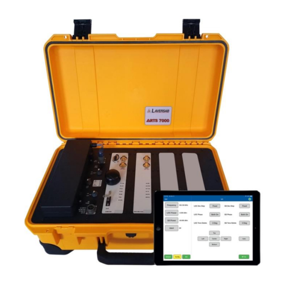
- Page 1 ARTS 7000 User Manual Aviation Systems Avionics Radio Test Set 7000 (ARTS 7000) Date: 19 November 2020 Rev A3 Page 1...
-
Page 2: Warranty
No representations or warranties are made with respect to the contents of this user's manual. Further, Laversab Inc. reserves the right to revise this manual and to make changes from time to time in the content hereof without obligation to notify any person of such revision. -
Page 3: Revision History
ARTS 7000 User Manual Aviation Systems EVISION ISTORY Document No. Release Date Description 125-9120A1 27/07/2020 ARTS-7000 User Manual Rev A1 125-9120A2 31/08/2020 ARTS-7000 User Manual Rev A2 125-9120A3 19/11/2020 ARTS-7000 User Manual Rev A3 Rev A3 Page 3... -
Page 4: Warning
ARTS 7000 User Manual Aviation Systems WARNING THE ARTS 7000 USES LINE VOLTAGES AND RADIO FREQUENCY SIGNALS FOR ITS OPERATION WHICH ARE POTENTIALLY DANGEROUS. IMPROPER OPERATION OF THIS EQUIPMENT MAY RESULT IN PERSONAL INJURY OR LOSS OF LIFE. HENCE THE EQUIPMENT DESCRIBED IN THIS MANUAL SHOULD BE OPERATED ONLY BY PERSONNEL TRAINED IN PROCEDURES THAT WILL ASSURE SAFETY TO THEMSELVES, TO OTHERS AND TO THE EQUIPMENT. -
Page 5: Table Of Contents
Subsection 4: Key Features ..........................12 Section 2: ARTS 7000 Test Set Hardware Controls & Connections ..............13 Subsection 1: ARTS 7000 Test Set Hardware, Controls & Connections ............. 13 Subsection 2: Hardware & Antenna Test Configuration ................23 Section 3: Controller & User Interface ........................24 Subsection 1: Description of Test Controller Application ................ - Page 6 ARTS 7000 User Manual Aviation Systems Subsection 2: COM AM Test Control Details ....................59 Section 9: VHF COM Frequency Modulation (FM) ....................60 Subsection 1: COM VHF FM Operation ......................60 Subsection 2: COM FM Test Control Details ....................63 Section 10: COM High Frequency (HF) Single Side Band (SSB) ................64...
- Page 7 ARTS 7000 User Manual Aviation Systems Appendix C: Laversab Test Default Settings ......................136 Rev A3 Page 7...
-
Page 8: Notes On This Document
Aviation Systems OTES ON THIS DOCUMENT This document is intended to be a guide to the normal operation of the ARTS 7000 Test System. This manual will explain the technical specifications, features and functions of the ARTS 7000. It has been written as a user reference for the test set operator. It does not detail any specific test procedure or process for any aircraft or aircraft system. -
Page 9: Section 1: Introduction
• Accessories housed within a lightweight pouch that can be attached to the main case. • Commercial off the shelf tablet control of the test set • Wi-Fi Control from tablet controller to ARTS 7000 test set using a unique ARTS 7000 self-generated Wi-Fi Network. -
Page 10: Subsection 3: Key Capabilities
UBSECTION APABILITIES Capability of the ARTS 7000 is defined by which modules are fitted to the test set. There are 3 standard configurations: Nav/Com only, Pulse only, or Nav/Com and Pulse. The following identifies the capabilities by module and technology group. - Page 11 ARTS 7000 User Manual Aviation Systems ARTS 7000 Key Configuration/Capability Chart Communication Navigation Transponder ARTS 7000 Configuration/ Capability Nav/Com Module Only Pulse Module Only Nav/Com and Pulse Modules Rev A3 Page 11...
-
Page 12: Subsection 4: Key Features
ARTS 7000 User Manual Aviation Systems 4: K UBSECTION EATURES All accessories are included with the standard test system. 1. Quick setup 2. Simple menus 3. Easy Software updates 4. Built in Utilities for ease of test system management and control 5. -
Page 13: Section 2: Arts 7000 Test Set Hardware Controls & Connections
The ARTS 7000 is housed in a high-quality ruggedized roller case. Test Set Dimensions: Approximate dimensions – ARTS 7000 main test set case measures 22” x 14” x 9” and weighs 30 lbs or 56cm x 36cm x 23cm and weighs 14 kg. Weight dependent on configuration. - Page 14 ARTS 7000 User Manual Aviation Systems 2.1.2. ARTS 7000 Test Set Top Panel Item Description Battery – Removable battery Power Switches and Connections – Power control Nav/Com Module – Used for all Navigation and Communication functions. Pulse Module – Used for all Pulse (Transponder/DME/TCAS) functions Expansion Slot –...
- Page 15 Unit Power Switch – Main Power switch for setting the unit On - Off Power LED Indicator Panel • Unit: Lit when the ARTS 7000 is on and active. • Power: Lit when the ARTS 7000 is has a suitable power source available •...
- Page 16 Used for connecting the ARTS 7000 Test Antenna for over the air testing. Cable Connection (100W Maximum): Used for Direct /Cable connection between the ARTS 7000 Test Set and a radio or antenna feeder. WIFI Antenna GPS Antenna COM LED Indicator: Lit during an active COM test.
- Page 17 ARTS 7000 is sending an interrogation to the Radio/Aircraft under test. (Normally flashing during the Interrogation) RPLY LED Indicator: Lit whenever the ARTS 7000 is Receiving a reply from the Radio/Aircraft under test. (Normally flashing during the Reply) Rev A3...
- Page 18 ARTS 7000 User Manual Aviation Systems 2.1.6. Expansion Slots Item Description Expansion Slot Number 1: Used for future capability expansion. Expansion Slot Number 2: Used for future capability expansion. Ground Connection point. 2.1.7. General accessories Accessory Storage case Antenna Mounting Tripod 3.
- Page 19 ARTS 7000 User Manual Aviation Systems 2.1.8. Nav Com Antenna 1. NAV/COM Telescopic antenna in Telescopic 3. NAV/Com Telescopic Antenna operation on an ARTS 7000 Test Set antenna tripod mouting adater Item Description Part Number 1 & 2 Telescopic Antenna for all Nav Com Functions.
- Page 20 The Pulse antenna is designed to be highly directional and as such, careful alignment between the ARTS 7000 Pulse antenna and the aircraft system under test antenna is required. NOTE the front of the antenna that should be directed to the antenna under test is the side embossed with the Laversab name and Logo.
- Page 21 3. A clear line of sight is required between the antenna under test and the ARTS 7000 a pulse antenna. 4. Ensure that there are no objects - tool boxes, ground power units, air stairs, gantries, landing gear etc.
- Page 22 India Power Cable (6 Feet) 129-1260 vi. China Power Cable (6 Feet) 129-1425 vii. Australia Power Cable (6 Feet) 129-1440 vii. External Attenuator 123-0235 Shown Note: Not all items will be included, unless specifically ordered from Laversab. Rev A3 Page 22...
-
Page 23: Subsection 2: Hardware & Antenna Test Configuration
ARTS 7000 User Manual Aviation Systems 2: H & A UBSECTION ARDWARE NTENNA ONFIGURATION Antenna and Cable configurations by capability Antenna to Antenna Direct Applicable Applicable ARTS 7000 Version Over-the- Cable Cable Connection Test connection Function Antenna Optional 131-0342A1 131-0340A1... -
Page 24: Section 3: Controller & User Interface
ONTROLLER PPLICATION 3.1.1. The ARTS 7000 test system uses a commercial off the shelf tablet as a controller. The ARTS 7000 test set tablet controller is connected over a Wi-Fi network. This Wi-Fi network is generated by the ARTS test set and does not need to be connected to another network in order to operate. - Page 25 Runs a basic self-test/confidence check of the ARTS 7000 Test System hardware. Check It is recommended to complete this function before the ARTS 7000 is used. Indicates the current version of software installed on Test Control Tablet and the Software ARTS 7000 Test Set.
- Page 26 ARTS 7000 User Manual Aviation Systems Navigation Menu Selects the Instrument Landing System (ILS) capability test page. Selects the Marker Beacon test page. ILS& Selects the combined Instrument Landing System and Marker Beacon test page. Selects the VHF Omnidirectional Ranging (VOR) test page.
- Page 27 ARTS 7000 User Manual Aviation Systems COM Menu Selects the Com Amplitude Modulation (AM) capability test page. Selects the Com Frequency Modulation (FM) capability test page. HF SSB Selects the COM High Frequency SSB capability test page. SelCal Selects the SELCAL capability test page.
- Page 28 ARTS 7000 User Manual Aviation Systems ELT Menu Selects the Emergency Location Transmitter capability test page. 121.5 MHz, 243MHz and 406 MHz DME Menu Selects the Distance Measuring capability test page. Selects the DME and combined ILS capability test page. This ILS &...
- Page 29 Selects the Mode ADSB Out Test Functions – ADSB Out generated from the aircraft under test Selects the Mode ADSB In Test Functions – ADSB IN generated ADSB from the ARTS 7000 to the aircraft under test (Under development) Rev A3...
- Page 30 ARTS 7000 User Manual Aviation Systems Mode S Menu Mode S Selects the Mode S Generic Basic Test Page. The basic test is all MODE S of the basic mode S parameters but does not include every ADSB Generic Basic element Selects the Mode S Generic Full Test Page.
- Page 31 ARTS 7000 User Manual Aviation Systems ATCRBS Menu ATCRBS Generic Selects the Generic ATCRBS test page. The is a generic ATCRBS test that meets Far 43 Appendix F ATCRBS Selects the Generic ATCRBS class A Transponder test page. This ATCRBS...
-
Page 32: Subsection 3: Test Controller Application Software Update
ORMAL OR RAINING The ARTS 7000 Test Control Application can be operated in 2 Modes 1. Normal operation mode i.e. connected to an ARTS 7000 test set and used for testing aircraft Systems. See the Test System Setup Section. 2. Demo or Training Mode. In this mode there is no requirement for a connection to an ARTS 7000 Test Set. -
Page 33: Section 4: Test System Setup
I CONNECTION AND PPLICATION TART 1. Set up the ARTS 7000 test system on level ground or bench top making sure there are no hazards that may damage the test system or harm the operator. 2. Apply Power to the ARTS 7000. - Page 34 13. The Tablet controller will now show the following screen. 14. Select Connect. 15. The ARTS 7000 will run through some basic confidence checks and establish a connection to the ARTS 7000 Test Box. 16. Once the Quick check is Complete the Controller tablet will show the main menu. The Test Set is now ready for use.
- Page 35 ARTS 7000 User Manual Aviation Systems Generic Controls and Indicators There are some key features to the application that are available on all screens. These are defined here: Item Description Exit Button takes the user back to the previous menu page.
- Page 36 Green Shows that The default button is only active from a test page. When pushed the test set is configured to A Laversab default setting specific to the selected test. The Config button is only available from an active test page...
-
Page 37: Subsection 2: Hardware Set Up
UBSECTION ARDWARE SET UP If testing over-the-air i.e. ARTS 7000 antenna to Aircraft under test antenna. For Nav Com functions connect the antenna part number 123-0239 directly to the antenna port on the top nav com module. Extend the antenna to its fullest length. -
Page 38: Section 5: Integrated Landing System (Ils) Operation
DEFAULT button or accessing the config page via the CONFIG button to establish the user preferences. The ARTS 7000 stores the last configuration used and also has a default setting. When the DEFAULT button on the test screen is pressed the ARTS 7000 automatically sets the default mode and settings. - Page 39 ARTS 7000 User Manual Aviation Systems ILS Configuration Screen ILS Configuration Controls and Selections Item Description Selects the over the air (Antenna) connection Port or the Direct (Cable) Connection Port. Allows the selection of the test Localizer Frequency. Preset (Laversab defined) Channel (Standard ILS LOC frequencies) or Variable.
- Page 40 Sets the ARTS 7000 output power of the Localizer signal. During the active test operation fine adjust is available see below. Sets the ARTS 7000 output power of the Glide Slope signal. During the active test operation fine adjust is available see below.
- Page 41 ARTS 7000 User Manual Aviation Systems LOC Phase adjusts the phase relationship between the 90 & 150Hz tones. Selects the removal of the 90Hz, 150Hz or both 90Hz and 150Hz elements of the Localizer. Used to confirm receiver fail indication on loss of a valid signal element.
-
Page 42: Subsection 2: Ils Test Control And Operation Details
4. Ident: Allows the use to select the audio identifier of the ARTS 7000 generated ILS signal. Possible Selections are: a. Off – No Audio Ident b. - Page 43 Glide Slope is moved across its range. 7. AUTO: when the Auto function is enabled the ARTS 7000 sets up Localizer and Glideslope signals IAW the preset Frequencies and Power. The ILS signal from the ARTS 7000 then imitates a corkscrew-type motion of the Localizer and Glideslope.
-
Page 44: Section 6: Marker Beacon (Mkr) Operation
DEFAULT button or accessing the config page vis the CONFIG button to establish the user preferences. The ARTS 7000 stores the last configuration used and also has a default setting. When the DEFAULT button on the test screen is pressed the ARTS 7000 automatically sets the default mode and settings. - Page 45 ARTS 7000 User Manual Aviation Systems Mkr Configuration Screen Mkr Configuration Controls and Selections Item Description Selects the over the air (Antenna) connection Port or the Direct (Cable) Connection Port. Allows the selection of the test power units for the Mkr Beacon.
- Page 46 Sets Mkr Frequency. Fixed at 75 MHz. During the active test operation fine adjust is available see below. Sets the ARTS 7000 output power of the Mkr Beacon signal. During the active test operation fine adjust is available see below.
- Page 47 ARTS 7000 User Manual Aviation Systems Used to select and toggle the active Outer 400 Hz Marker signal. Indicates the active Signal when highlighted with the Color Blue Used to select and toggle the active Middle 1300Hz Marker signal. Indicates the active Signal when...
-
Page 48: Subsection 2: Mkr Test Control Details
UBSECTION ONTROL ETAILS 1. Frequency: Sets the frequency of the ARTS 7000 generated Marker Beacon frequency. This frequency is fixed at 75MHz. a. Note: when the test is running the Frequency can be course and fine-tuned to allow selectivity testing. This done by pressing the Frequency numerical field. A pop up is then displayed to allow adjustment of the Transmitted Frequency. -
Page 49: Section 7: Vhf Omnidirectional Ranging (Vor) Operation
DEFAULT button or accessing the config page vis the CONFIG button to establish the user preferences. The ARTS 7000 stores the last configuration used and also has a default setting. When the DEFAULT button on the test screen is pressed the ARTS 7000 automatically sets the default mode and settings. - Page 50 Selects the over the air (Antenna) connection Port or the Direct (Cable) Connection Port. Allows the selection of the test VOR Frequency. Selections are Preset (Laversab defined), Channel (Standard VOR frequencies) or Variable. Allows the selection of the test power units for the VOR Signal.
- Page 51 Sets Frequency of the ARTS 7000 Generated VOR signal During the active test operation fine adjust is available see below. Sets the output power of the ARTS 7000 generated VOR signal. During the active test operation fine adjust is available see below.
- Page 52 Allows adjustment of the modulation of the 9960Hz sub carrier Modulation Depth Indicates the current bearing of the VOR signal being transmitted from the ARTS 7000. Under normal test condition the aircraft display should show this bearing. Steps the VOR Bearing anti clockwise 1 Step. Each step size is selected from the Config Page.
-
Page 53: Subsection 2: Vor Test Control Details
9. AUTO – when the Auto function is enabled the ARTS 7000 sets up a VOR signal IAW the selected frequencies, Power Modulation and Ident. The VOR signal from the ARTS 7000 then automatically steps the bearing in the selected step range from 0 Degrees to 360... - Page 54 Degrees. Once this full-scale sweep is complete the VOR signal will be reversed from 360 Degrees to 0 Degrees. The ARTS 7000 will continue to sweep the bearing through full range until the Auto button is pressed again. This sweeping the instrumentation across full scale.
-
Page 55: Section 8: Vhf Com Amplitude Modulation (Am)
DEFAULT button or accessing the config page vis the CONFIG button to establish the user preferences. The ARTS 7000 stores the last configuration used and also has a default setting. When the DEFAULT button on the test screen is pressed the ARTS 7000 automatically sets the default mode and settings. - Page 56 Selects the over the air (Antenna) connection Port or the Direct (Cable) Connection Port. Allows the selection of the test Com AM Frequency. Selections are Preset (Laversab defined), Channel (Standard Com AM frequencies) or Variable. Allows the selection of the test power units for the Com AM Signal.
- Page 57 Sets Frequency of the ARTS 7000 Generated COM AM signal During the active test operation fine adjust is available see below. Sets the output power of the ARTS 7000 generated COM AM signal. During the active test operation fine adjust is available see below.
- Page 58 ARTS 7000 User Manual Aviation Systems Toggles the ARTS 7000 from Receive to Transmit mode. On Start up the ARTS 7000 is always in Receive mode. Press this button for Transmit. During an active test this field will indicate the Transmitted Frequency from the Aircraft.
-
Page 59: Subsection 2: Com Am Test Control Details
Tone – the ARTS 7000 generates a constant 1kHz audio tone. 5. Frequency (indication): Indication of the received frequency from the Aircraft transceiver. This field is only active when the ARTS 7000 is in receive mode and receives a signal from the aircraft when PTT is active. -
Page 60: Section 9: Vhf Com Frequency Modulation (Fm)
DEFAULT button or accessing the config page vis the CONFIG button to establish the user preferences. The ARTS 7000 stores the last configuration used and also has a default setting. When the DEFAULT button on the test screen is pressed the ARTS 7000 automatically sets the default mode and settings. - Page 61 Selects the over the air (Antenna) connection Port or the Direct (Cable) Connection Port. Allows the selection of the test COM FM Frequency. Selections are Preset (Laversab defined), Channel (Standard COM FM frequencies) or Variable. Allows the selection of the test power units for the COM FM Signal.
- Page 62 Sets Frequency of the ARTS 7000 Generated COM FM signal. During the active test operation fine adjust is available see below. Sets the output power of the ARTS 7000 generated COM FM signal. During the active test operation fine adjust is available see below.
-
Page 63: Subsection 2: Com Fm Test Control Details
Tone – the ARTS 7000 generates a constant 1kHz audio tone. 5. Frequency (indication): Indication of the received frequency from the Aircraft transceiver. This field is only active when the ARTS 7000 is in receive mode and receives a signal from the aircraft when PTT is active. -
Page 64: Section 10: Com High Frequency (Hf) Single Side Band (Ssb)
DEFAULT button or accessing the config page vis the CONFIG button to establish the user preferences. The ARTS 7000 stores the last configuration used and also has a default setting. When the DEFAULT button on the test screen is pressed the ARTS 7000 automatically sets the default mode and settings. - Page 65 ARTS 7000 User Manual Aviation Systems COM SSB HF Test Configuration Screen COM SSB HF Test Configuration Controls and Selections Item Description Selects the over the air (Antenna) connection Port or the Direct (Cable) Connection Port. Allows the selection of the test power units for the COM SSB HF Signal.
- Page 66 Sets Frequency of the ARTS 7000 Generated COM SSB HF signal. During the active test operation fine adjust is available see below. Sets the output power of the ARTS 7000 generated COM SSB HF signal. During the active test operation fine adjust is available see below.
-
Page 67: Subsection 2: Com Hf Test Control Details
Tone – the ARTS 7000 generates a constant 1kHz audio tone. 5. Frequency (indication): Indication of the received frequency from the Aircraft transceiver. This field is only active when the ARTS 7000 is in receive mode and receives a signal from the aircraft when PTT is active. -
Page 68: Section 11: Com Selcal
DEFAULT button or accessing the config page vis the CONFIG button to establish the user preferences. The ARTS 7000 stores the last configuration used and also has a default setting. When the DEFAULT button on the test screen is pressed the ARTS 7000 automatically sets the default mode and settings. - Page 69 Selects the over the air (Antenna) connection Port or the Direct (Cable) Connection Port. Allows the selection of the test Frequency. Selections are Preset (Laversab defined), Channel (Standard COM FM frequencies) or Variable. Allows the selection of the test power units for the COM SSB HF Signal.
- Page 70 Sets the output power of the ARTS 7000 generated COM SelCal signal. During the active test operation fine adjust is available see below. Sets the % level of modulation of the ARTS 7000 generated COM SelCal signal. Used to select the 4-digit SelCal code to match the test aircraft.
-
Page 71: Subsection 2: Com Selcal Test Control Details
Transmitted Frequency. 3. Modulation: Sets the modulation level of the ARTS 7000 generated COM SelCal signal. 4. SelCal Tone: Sets the 4-digit SelCal code to match the test aircraft. -
Page 72: Section 12: Elt Emergency Location Transmitters
DEFAULT button or accessing the config page vis the CONFIG button to establish the user preferences. The ARTS 7000 stores the last configuration used and also has a default setting. When the DEFAULT button on the test screen is pressed the ARTS 7000 automatically sets the default mode and settings. - Page 73 ARTS 7000 User Manual Aviation Systems ELT Test Configuration Screen ELT Test Configuration Controls and Selections Item Description Selects the over the air (Antenna) connection Port or the Direct (Cable) Connection Port. Allows selection of the data format for 406 MHz ELT...
- Page 74 ARTS 7000 User Manual Aviation Systems ELT Test Screen ELT Main Page Test Controls and Selections Item Description Selects the 121.5 MHz ELT Test Screen (see below) Selects the 121.5 MHz ELT Test Screen (see below) Selects the 406 MHz ELT Test Screen (see below)
- Page 75 ARTS 7000 User Manual Aviation Systems 121.5 MHz ELT Test Screen 243 MHz ELT Test Screen Rev A1 Page 75...
- Page 76 ARTS 7000 User Manual Aviation Systems 406 MHz ELT Test Screen ELT Test Controls and Selections Item Description Highest frequency of the modulated sweep. Only available on 121.5 and 243 MHz ELTs Lowest frequency of the modulated sweep. Only available on 121.5 and 243 MHz ELTs...
-
Page 77: Subsection 2: Elt Test Control And Indicator Details
The ARTS 7000 will decode and display the data for either the Long or Short Messages (i.e. whichever one the ELT beacon is transmitting). 4. The ELT 406 MHz received data is stored in the ARTS 7000 App and can be downloaded at any time... -
Page 78: Section 13: Distance Measuring Equipment (Dme)
DEFAULT button or accessing the config page vis the CONFIG button to establish the user preferences. The ARTS 7000 stores the last configuration used and also has a default setting. When the DEFAULT button on the test screen is pressed the ARTS 7000 automatically sets the default mode and settings. - Page 79 Variable. Allows the selection of the test power units for the DME Signal. Selections are dBm, mV, uV. This field identifies the range from the ARTS 7000 pulse antenna to Antenna Range the Aircraft DME Antenna in Feet.
- Page 80 Aviation Systems Only required on an antenna to antenna (over the air) connection. Selects the length of the cable used between the ARTS 7000 direct connection connector and the Aircraft Radio or feeder. This allows the ARTS 7000 to calculate the loss in the cable.
- Page 81 Scenario Attribute – Sets the pseudo range from the test aircraft to the ARTS 7000 generated DME beacon. Selects the quantity of replies by the ARTS 7000 to the aircraft interrogation signal Switches Squitter on or off. Squitter must be on to allow the...
-
Page 82: Subsection 2: Dme Test Control Details
DME Beacon generated by the ARTS 7000. 6. % Replies: The % replies can be adjusted from 1-100%. This allows the response from the ARTS 7000 to be artificially degraded to confirm correct operation of the DME in low signal or signal loss conditions. - Page 83 13. P1 – P2 Spacing (indication): This field indicates the spacing between the P1 and P2 interrogation pulses received at the ARTS 7000 from the signal from the aircraft interrogator. 14. PRF (Indication): Indicates the Pulse Repetition frequency of the interrogation pulses transmitted to the ARTS 7000 from the Aircraft interrogator.
-
Page 84: Section 14: Modes Transponders
All ARTS 7000 Mode S transponder testing is carried out in accordance with Far 43 Appendix F requirements. Please ensure that using the ARTS 7000 that you are aware of the specific requirements of FAR 43 Appendix F and any other local transponder testing requirements. - Page 85 ARTS 7000 User Manual Aviation Systems The options and descriptions of each test type are below: Test Name Description The Generic Mode S Basic test is a quick verification test of the key parameters of the Mode S transponder. This test includes the frequency, power and pulse characteristic checks of the Mode S reply only.
-
Page 86: Subsection 2: Modes Test Guide
Antenna alignment is critical to successful testing of transponders. The ARTS 7000 pulse antenna is highly directional in both x and y planes and must be positioned in such a way that the center point of the antenna is pointed as accurately as possible to the aircraft antenna under test. - Page 87 ARTS 7000 User Manual Aviation Systems ARTS 7000 Pulse antenna showing good alignment with an aircraft bottom antenna. Please see the section on Pulse Antenna Alignment, Reflections and Multi-path. 1. Transponder testing may take > 20 minutes depending on the capability of the transponder.
- Page 88 ARTS 7000 User Manual Aviation Systems MODE S Test Selection 1. From the Main Menu Select Test Functions. 2. From the Functions menu select ATC. 3. From the ATC Menu select Mode S. 4. From the MODE S menu select which Mode S Test is required – see table above.
- Page 89 Yes, for a diversity aircraft installation (top and bottom antenna) no Diversity Test for a non-diverse aircraft installation (single Antenna) Selects the length of the cable used between the ARTS 7000 antenna connector and the ARTS 7000 pulse antenna. This allows the ARTS Ant Cable Length 7000 to calculate the loss in the cable.
- Page 90 ARTS 7000 User Manual Aviation Systems the ARTS 7000 connector and the ARTS 7000 Pulse antenna- this is used to calculate the loss in the cable. When testing MODE S over a direct/cable connection – this field is Direct Cable Length (6, 20 or 60 ft used to identify which length of coax cable that is being used between the ARTS 7000 connector and the aircraft units’...
- Page 91 Aviation Systems Mode S Test Controls and Selections Item Description In test indication of the ARTS 7000 received frequency from the Aircraft Frequency transponder’s reply. In test indication of the power of the Aircraft transponder’s reply from the Aircrafts Top ERP top antenna.
-
Page 92: Subsection 3: Mode S Results Screen
1. Above is the main test screen for Mode S. During the test and after the test is complete the fields indicated will display the relevant data. 2. Once the test is complete the ARTS 7000 stores the results that can be viewed and downloaded from the Utilities>Records menu. - Page 93 ARTS 7000 User Manual Aviation Systems 3. Test Results shown in Green have passed the specification those shown in red have failed. 4. When the test is completed please push the LIST TEST button this will launch the screen below.
- Page 94 ARTS 7000 User Manual Aviation Systems Mode S Mode S Specific Pulse characteristics. Characteristics ADS-B Specific data transmitted in the aircraft reply stored within DF0. ADS-B Specific data transmitted in the aircraft reply stored within DF4. ADS-B Specific data transmitted in the aircraft reply stored within DF5.
- Page 95 ARTS 7000 User Manual Aviation Systems Test Results Screen Details Screen shots of Mode S Module Test Results (Example data) Note: Whenever available the relevant BDS registers are accessed through the title bar of the results screen. Power Test Results Screen...
- Page 96 ARTS 7000 User Manual Aviation Systems Mode A Replies and Characteristics Test Results Screen Mode C Replies and Characteristics Test Results Screen Rev A1 Page 96...
- Page 97 ARTS 7000 User Manual Aviation Systems Mode S Replies Test Results Screen Mode S Characteristics Test Results Screen Rev A1 Page 97...
- Page 98 ARTS 7000 User Manual Aviation Systems DF0 Test Results Screen DF4 Test Results Screen Rev A1 Page 98...
- Page 99 ARTS 7000 User Manual Aviation Systems DF 5 Test Results Screen DF11 Test Results Screen Rev A1 Page 99...
- Page 100 ARTS 7000 User Manual Aviation Systems DF16 Test Results Screen DF17 Test Results Screen Rev A1 Page 100...
- Page 101 ARTS 7000 User Manual Aviation Systems DF18 Test Results Screen To Be updated DF20 Test Results Screen Rev A1 Page 101...
- Page 102 ARTS 7000 User Manual Aviation Systems DF21 Test Results Screen DF 24 Test Results Screen Rev A1 Page 102...
-
Page 103: Section 15: Adsb Out
All ARTS 7000 Mode S transponder testing is carried out in accordance with Far 43 Appendix F requirements. Please ensure that using the ARTS 7000 that you are aware of the specific requirements of FAR 43 Appendix F and any other local transponder testing requirements. -
Page 104: Subsection 2: Adsb Test Guide
1. Antenna alignment is critical to successful testing of transponders. The ARTS 7000 pulse antenna is highly directional in both x and y planes and must be positioned in such a way that the center point of the antenna is pointed as accurately as possible to the aircraft antenna under test. - Page 105 DEFAULT button or accessing the config page vis the CONFIG button to establish the user preferences. The ARTS 7000 stores the last configuration used and also has a default setting. When the DEFAULT button on the test screen is pressed the ARTS 7000 automatically sets the default mode and settings.
- Page 106 Selects the over the air (Antenna) connection Port or the Direct Port Selection (Cable/Antenna) (Cable) Connection Port. IF an external attenuator is used between the ARTS 7000 and the External Attenuator unit under test – sets the value of the attenuator.
- Page 107 Description In test indication of the ARTS 7000 received Frequency from the Aircraft RXD Frequency ADSB. Power of the signal received at the ARTS 7000 generated from the aircraft RXD Power ADSB transponder. ADSB Squittered – Aircraft Address Aircraft Address ADSB Squittered –...
-
Page 108: Subsection 3: Adsb Results Screen
1. Above is the main test screen for ADSB. During the test and after the test is complete, the fields indicated will display the relevant data. 2. Once the test is complete the ARTS 7000 stores the results that can be viewed and downloaded from the UTILITIES>RECORDS menu. - Page 109 ARTS 7000 User Manual Aviation Systems List Test Screen Select any of the results fields to review the specific modules test results. Test Results Screen Details Item Description of module contents Initial Test This links back to the basic test results screen...
- Page 110 ARTS 7000 User Manual Aviation Systems ADS-B Specific data transmitted in the aircraft reply stored within DF18. DF18 All Associated BDS registers data is available through the DF18 test result screen. ADS-B Specific data transmitted in the aircraft reply stored within DF20.
- Page 111 ARTS 7000 User Manual Aviation Systems DF4 Test Results Screen DF 5 Test Results Screen Rev A1 Page 111...
- Page 112 ARTS 7000 User Manual Aviation Systems DF11 Test Results Screen DF16 Test Results Screen Rev A1 Page 112...
- Page 113 ARTS 7000 User Manual Aviation Systems DF17 Test Results Screen DF18 Test Results Screen To Be updated Rev A1 Page 113...
- Page 114 ARTS 7000 User Manual Aviation Systems DF20 Test Results Screen DF21 Test Results Screen Rev A1 Page 114...
- Page 115 ARTS 7000 User Manual Aviation Systems DF 24 Test Results Screen Rev A1 Page 115...
-
Page 116: Section 16: Atcrbs Transponders
ARTS 7000 User Manual Aviation Systems 16: ATCRBS T ECTION RANSPONDERS 1: ATCRBS O UBSECTION PERATION WARNING It is extremely dangerous to generate signals during testing that are on the frequencies that are in use by local ATC. When operating the test set in ATCRBS Mode. Please be aware of the local navigation aid and ATC frequencies. It is the test set operator’s responsibility to make sure all testing is carried out on Frequencies that will not interfere with local navigation... - Page 117 ATCRBS test – Different Test options There are a number of different ATCRBS test that the ARTS 7000 is capable of completing. All of the tests operate in exactly the same way but have differing levels of performance. It is the operator’s choice as to which tests are applicable.
-
Page 118: Subsection 2: Atcrbs Test Guide
Antenna alignment is critical to successful testing of transponders. The ARTS 7000 pulse antenna is highly directional in both x and y planes and must be positioned in such a way that the center point of the antenna is pointed as accurately as possible to the aircraft antenna under test. - Page 119 ARTS 7000 User Manual Aviation Systems ARTS 7000 Pulse antenna showing good alignment with an aircraft bottom antenna. Please see the section on Pulse Antenna Alignment, Reflections and Multipaths. Transponder testing may take > 20 minutes depending on the capability of the transponder. It is recommended to choose the basic test first.
- Page 120 All ARTS 7000 ATCRBS transponder testing is carried out in accordance with Far 43 Appendix F requirements. Please ensure that using the ARTS 7000 that you are aware of the specific requirements of FAR 43 Appendix F and any other local transponder testing requirements.
- Page 121 DEFAULT button or accessing the config page vis the CONFIG button to establish the user preferences. The ARTS 7000 stores the last configuration used and also has a default setting. When the DEFAULT button on the test screen is pressed the ARTS 7000 automatically sets the default mode and settings.
- Page 122 Horizontal distance from the ARTS 7000 antenna to the aircraft’s ANT Range antenna entered in feet. Does not have to be 100% accurate. Vertical height from the ARTS 7000 antenna to the aircraft antenna Ant Height entered in feet. Does not have to be 100% accurate.
- Page 123 ATCRBS Test Screen ATCRBS Test Controls and Selections Item Description In test indication of the ARTS 7000 received Frequency from the Aircraft Frequency transponder’s reply. In test indication of the number of replies received from the aircraft related to Replies the number of interrogations sent to the aircraft in % In test indication of the power of the Aircraft transponder’s reply from the...
-
Page 124: Subsection 3: Atcrbs Results Screen
1. Above is the main test screen for ATCRBS. During the test and after the test is complete the fields indicated will display the relevant data. 2. Once the test is complete the ARTS 7000 stores the results that can be viewed and downloaded from the Utilities>Records menu. - Page 125 ARTS 7000 User Manual Aviation Systems List Test Screen Select any of the results fields to review the specific modules test results. Item Description of module contents Initial Test This links back to the basic test results screen Power ERP and MTL levels received from the Transponder under test replies.
- Page 126 ARTS 7000 User Manual Aviation Systems Test Results Screen Details Screen shots of ATCRBS Module Test Results (Example data) Power Test Results Screen Frequency Test Results Screen Rev A1 Page 126...
- Page 127 ARTS 7000 User Manual Aviation Systems Mode A Replies and Characteristics Test Results Screen Mode C Replies and Characteristics Test Results Screen Rev A1 Page 127...
-
Page 128: Section 17: Uat Transponders
ARTS 7000 User Manual Aviation Systems 17: UAT T ECTION RANSPONDERS 1: UAT O UBSECTION PERATION UAT is an optional capability and is currently under development Rev A1 Page 128... -
Page 129: Section 18: Tcas
ARTS 7000 User Manual Aviation Systems 18: TCAS ECTION 1: TCAS O UBSECTION PERATION TCAS is an optional capability and is currently under development. Rev A1 Page 129... - Page 130 ARTS 7000 User Manual Aviation Systems This page is left intentionally blank. Rev A1 Page 130...
-
Page 131: Appendix A: Technical Specifications
ARTS 7000 User Manual Aviation Systems A: T PPENDIX ECHNICAL PECIFICATIONS NAV/Com Functions ILS Specifications Parameter Specification LOC Frequency Range 107.00 to 113.00MHz in 1KHz steps LOC Pre Set Frequency Range 109.10MHz, 109.15MHz, 111.15MHz LOC Channel Frequency Range 108-112MHz in 1 kHz Steps... - Page 132 ARTS 7000 User Manual Aviation Systems MKr Specifications Parameter Specification MKr Power +13dBm to -83dBm in 0.25dBm steps MKr Power accuracy +/- 2dBm MKr Tone Frequency accuracy 400Hz 0.02 +/-% MKkr Tone Frequency accuracy 1300Hz 0.02+/-% MKr Tone Frequency accuracy 3000Hz 0.02+/-%...
- Page 133 ARTS 7000 User Manual Aviation Systems HF SSB Specifications Parameter Specification HF SSB Frequency Range 10 to 30 MHz HF SSB Frequency Steps 100 kHz HF SSB Frequency Accuracy +/-0.001% HF SSB Audio Tone 1000Hz SelCal Specifications Parameter Specification SELCAL Tone Frequency Accuracy +/- 0.2 %...
- Page 134 ARTS 7000 User Manual Aviation Systems Pulse Functions DME Specifications Parameter Specification Frequency Range 960-1215 MHz Frequency Accuracy Rx +/-0.5Mhz Frequency Accuracy Tx +/-10kHz Output Power Antenna -2dBm to -67dBm Output Direct connection -29dBm to -94dBm Distance to A/C Antenna...
-
Page 135: Appendix B: Spare Parts
Europe Power Cable (6 Feet) [129-1268] iv. Swiss Power Cable (6 Feet) [129-1311] Power Cable Optional ARTS 7000 Power cables v. India Power Cable (6 Feet) [129-1260] vi. China Power Cable (6 Feet) [129-1425] vii. Australia Power Cable (6 Feet) [129-1440] Accessory Case Storage case for antenna and cables. - Page 136 ARTS 7000 User Manual Aviation Systems PPENDIX AVERSAB EFAULT ETTINGS Laversab Test Default Settings Test Function Attribute Value Frequency 110.100MHz Power Loc -10 dBm Power GS -27 dBm Ident Morse (LSB) Frequency &% Mhz Default Power -14 dBm Modulation Frequency 112.200 MHz...
- Page 137 ARTS 7000 User Manual Aviation Systems Selcal Tone AAAA TX Mode Repeat Reply Freq 998.000 MHz Nav Freq 110.000 MHz Channel Power -25 dBm Rate KTS 150 Knots Range NM 50 NM Replies 100% SQTR ECHO Rev A1 Page 137...
Need help?
Do you have a question about the ARTS 7000 and is the answer not in the manual?
Questions and answers