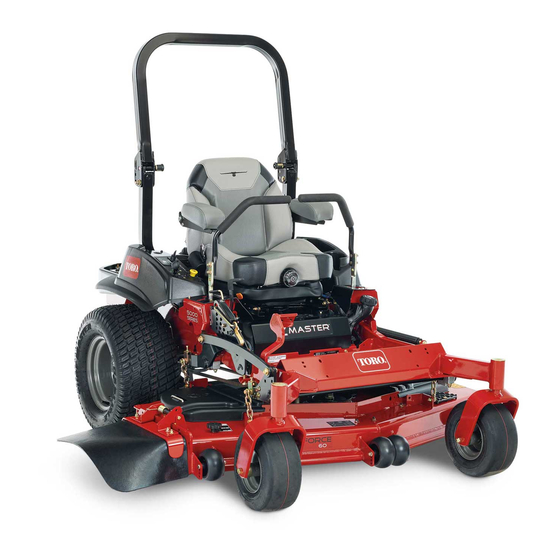
Toro Z Master Professional 5000 Series Setup Instructions
Hide thumbs
Also See for Z Master Professional 5000 Series:
- Operator's manual (92 pages) ,
- Operator's manual (76 pages) ,
- Operator's manual (68 pages)
Table of Contents
Advertisement
Quick Links
Z Master
For 3000 Through 7000 Series Models
Setup
Loose Parts
Use the chart below to verify that all parts have been shipped.
Procedure
1
2
3
4
5
6
7
8
9
10
11
12
13
© 2021—The Toro® Company
8111 Lyndale Avenue South
Bloomington, MN 55420
®
Riding Mower
Description
Rear wheels (wooden crate only)
No parts required
No parts required
No parts required
No parts required
No parts required
J-bolt
Wing nut
Hold-down clamp
Clamp
Wing nut (1/4 inch)
Battery hold-down
No parts required
Seat
Seat plate (fixed seats only)
Flange nuts (3/8 inch)—fixed seats only
Spacers (3/8 inch)—fixed seats only
Flange nuts (3/8 inch)—tilting seats only
Long spacers (tilting, deluxe seats only)
Short spacers (tilting, deluxe seats only)
No parts required
Right control lever
Left control lever
Bolt (3/8 x 1 inch)—2 are assembled
Nut (3/8 inch)—2 are assembled
Carriage bolt (3/8 x 1-1/2 inches)
Flange locknut (3/8 inch)
Register at www.Toro.com.
Form No. 3434-244 Rev B
Qty.
2
Remove the machine from a crate.
–
Add fuel to the machine.
–
Check the engine-oil level.
–
Check the tire pressure.
–
Check the wheel lug nut torque.
–
Check the grass deflector.
2
2
Install a battery (diesel machines only).
1
1
Install a battery (gasoline machines
2
only).
2
–
Charge the battery.
1
1
8
Install the seat (international machines
4
using gasoline only).
4
2
4
Check the seat belt (international
–
machines using gasoline only).
1
Install the motion-control levers
1
(international machines using gasoline
4
only).
4
1
Install the lift-assist pedal (international
machines using gasoline only).
1
Original Instructions (EN)
Printed in the USA.
All Rights Reserved
Setup Instructions
Use
*3434-244*
Advertisement
Table of Contents

Related Manuals for Toro Z Master Professional 5000 Series


Summary of Contents for Toro Z Master Professional 5000 Series
- Page 1 Carriage bolt (3/8 x 1-1/2 inches) Install the lift-assist pedal (international machines using gasoline only). Flange locknut (3/8 inch) *3434-244* © 2021—The Toro® Company Original Instructions (EN) 8111 Lyndale Avenue South Printed in the USA. Bloomington, MN 55420 Register at www.Toro.com.
-
Page 2: Table Of Contents
Procedure Description Qty. Air-cleaner cap Install the air-cleaner cap (international machines using gasoline only). Hose clamp Install the ROPS (international machines Rollover Protection System (ROPS) Kit using gasoline only). Roll bar, right section Roll bar, left section Roll bar, center section Bolt (3/8 x 1 inch) Install the ROPS (diesel machines only). - Page 3 g001088 Figure 5 g001059 Diesel Machine Shown Figure 2 Diesel Machine Shown Mount the wheels with the valve stem to the outside and secure them with the wheel nuts Raise the rear of the machine and support it previously removed. with jack stands.
- Page 4 Adding Fuel to the Machine Checking the Wheel Lug Nut Torque No Parts Required No Parts Required Procedure Procedure Add fuel to the machine before starting it. Refer to your Operator’s Manual for the correct fuel and Before you start the engine and use the machine, procedure.
- Page 5 Installing a Battery Gasoline Machines Only Parts needed for this procedure: Clamp Wing nut (1/4 inch) Battery hold-down g021181 Procedure Figure 8 Important: This procedure applies only to 1. Grass deflector 3. End of the spring machines that do not come with a battery 2.
- Page 6 Charge the battery; refer to the Operator's Manual for instructions. g001084 g010175 Figure 9 Figure 10 1. Hydraulic-unit shroud 2. Bolts Remove the 4 nuts holding the seat plate to the machine. Discard these nuts, they are used for shipping only. Installing the Seat International Machines Using Gasoline Only...
- Page 7 g010184 Figure 12 Plug the harness connector into the seat switch located under the seat towards the front. Install the seat to the machine frame with 4 flange nuts (3/8 inch). g030558 Figure 14 For machines with a deluxe seat only 1.
- Page 8 Checking the Seat Belt Installing the Motion-Control Levers International Machines Using Gasoline Only International Machines Using Gasoline Only No Parts Required Parts needed for this procedure: Procedure Right control lever Important: Ensure the bolt torque is set between Left control lever 67 to 83 N∙m (49 to 61 ft-lb).
- Page 9 g009195 Figure 18 g016346 Figure 19 Note: If the machine is not properly tracking, 1. Lift-assist pedal 3. Carriage bolt (3/8 x 1-1/2 refer to Adjusting the Tracking in your Operator's inches) Manual. 2. Flange locknut (3/8 inch) Installing the Lift-Assist Pedal International Machines Using Gasoline Only...
-
Page 10: Procedure
Installing the Air-Cleaner International Machines Using Gasoline Only g001659 Parts needed for this procedure: Figure 21 Air-cleaner cap Install the air-cleaner cap onto the air cleaner Hose clamp and secure it with the hose clamp. Procedure Note: Not all the machines come with a heavy duty air cleaner. -
Page 11: Rollover Protection System (Rops) Kit
Installing the ROPS International Machines Using Gasoline Only Parts needed for this procedure: Rollover Protection System (ROPS) Kit g001077 Figure 23 Procedure Install the lanyard clips onto the long bolts (1/2 x Install the Rollover Protection System (ROPS) Kit. 3-1/4 inches). Follow the Installation Instructions. - Page 12 Note: No more than 1 thread should be exposed outside the nut. g003294 Figure 25 g003295 Figure 27 Raise the roll bar into the upright position and secure it with the pins and hairpin cotters fastened to the lanyards. g030555 Figure 26 Torque all of the lower fasteners attached to the machine frame to 40.7 N∙m (30 ft-lb).
-
Page 13: 2 Lithium Or Molybdenum Grease
Checking the Machine for Removing the Shipping Grease Straps For Machines with MyRide ™ Parts needed for this procedure: Suspension System Only No. 2 lithium or molybdenum grease. (Purchase 1 tube separately.) No Parts Required Procedure Procedure Before you use the machine, check the machine for grease;... -
Page 14: No Parts Required
Checking the Machine Before Delivery to the Customer For All Machines No Parts Required Procedure Before delivering the machine to the customer, ensure that you perform or have performed the procedures listed in the following table and initial each when finished. Refer to the Operator's Manual for instructions on performing these procedures. -
Page 15: Operator's Manual
Delivering the Machine to the Customer For All Machines Parts needed for this procedure: Operator's Manual Engine Owner's Manual Registration card Operator training material Procedure At delivery, fill in the model and serial number, complete the items listed in the following table, and initial each when finished. - Page 16 Make sure that the customer receives the Operator's Manual, Engine Owner's Manual, Set Up Instructions, and operator training material. Make sure the customer knows the Parts Catalog is available at www.Toro.com. Assist the customer in loading the machine. Note: When you, the dealer representative, have finished delivering the machine to the customer, sign and date in the space provide below and keep a copy of this page for dealer records.