Toro 74915 Operator's Manual
With 60in or 72in turbo force side discharge mower
Hide thumbs
Also See for 74915:
- Service manual (188 pages) ,
- Operator's manual (76 pages) ,
- Operator's manual (68 pages)
Table of Contents
Advertisement
Quick Links
Advertisement
Table of Contents

Related Manuals for Toro 74915


Summary of Contents for Toro 74915
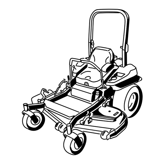
- Page 1 Z Master ® Professional 5000 Series Riding Mower with 60in or 72in TURBO FORCE ® Side Discharge Mower Model No. 74915—Serial No. 313000001 and Up Model No. 74916—Serial No. 313000001 and Up g019887 *3375-592* A Register at www.Toro.com. Original Instructions (EN)
-
Page 2: Introduction
Whenever you need service, genuine Toro parts, or additional WARNING information, contact an Authorized Service Dealer or Toro Customer Service and have the model and serial numbers of CALIFORNIA your product ready. Figure 1 identifies the location of the Proposition 65 Warning model and serial numbers on the product. -
Page 3: Table Of Contents
Contents Checking the Rollover Protection System (ROPS) Knobs...............41 Adjusting the Tracking ..........41 Introduction ..............2 Checking the Tire Pressure ........41 Safety ................4 Checking the Wheel Lug Nuts ........42 Safe Operating Practices........... 4 Checking the Wheel Hub Slotted Nut ......42 Slope Indicator ............ -
Page 4: Safety
Operation Safety • Lightning can cause severe injury or death. If lightning is seen or thunder is heard in the area, do not operate Improper use or maintenance by the operator or owner can the machine; seek shelter. result in injury. To reduce the potential for injury, comply with these safety instructions and always pay attention to the safety •... - Page 5 Safe handling of fuels • Use care when checking blades. Wrap the blade(s) or wear gloves, and use caution when servicing them. Only • To avoid personal injury or property damage, use replace blades. Never straighten or weld them. extreme care in handling gasoline. Gasoline is extremely •...
-
Page 6: Slope Indicator
Slope Indicator G011841 Figure 3 This page may be copied for personal use. 1. The maximum slope you can safely operate the machine on is 15 degrees. Use the slope chart to determine the degree of slope of hills before operating. Do not operate this machine on a slope greater than 15 degrees. Fold along the appropriate line to match the recommended slope. -
Page 7: Safety And Instructional Decals
Safety and Instructional Decals Safety decals and instructions are easily visible to the operator and are located near any area of potential danger. Replace any decal that is damaged or lost. 68-8340 1-403005 98-5954 103-2076 54-9220 58-6520 1. Grease 105-7798 66-1340... - Page 8 110-2067 110-2068 1. Read the Operator's Manual. 107-2102 114-4466 1. Main, 25A 3. Charge, 25A 2. PTO, 10A 4. Auxiliary, 15A 109-7232...
- Page 9 116-0205 115-7445 1. Grease pulleys and spindles 2. Maintenance interval—50 hours 116-0211 Manufacturer's Mark 1. Indicates the blade is identified as a part from the original machine manufacturer. 116-0090 116-0157...
- Page 10 116-3303 116-0752 1. Locked 2. Unlocked 116-4858 116-1654 116-5944 116-1716 1. Fuel 6. Hour meter 2. Empty 7. PTO 3. Half 8. Parking brake 4. Full 9. Neutral 5. Battery 10. Operator presence switch 116-2643...
- Page 11 Battery Symbols Some or all of these symbols are on your battery 1. Explosion hazard 6. Keep bystanders a safe distance from the battery. 2. No fire, open flame, or 7. Wear eye protection; smoking. explosive gases can 120-5897 cause blindness and other injuries 1.
-
Page 12: Product Overview
Fuel Gauge Product Overview The fuel gauge is located with the hour meter and the bars light up when the ignition switch is on (Figure 6). The indicator light appears when the fuel level is low (approximately one gallon remaining in the fuel tank). Safety Interlock Indicators There are symbols on the hour meter and the indicate with a black triangle that the interlock component is in the correct... -
Page 13: Specifications
Roll Bar - Up Roll Bar - Down its capabilities. Contact your Authorized Service Dealer or Distributor or go to www.Toro.com for a list of all approved 70.5 inches (179.1 cm) 46.8 inches (118.9 cm) attachments and accessories. -
Page 14: Operation
Operation DANGER In certain conditions during fueling, static Note: Determine the left and right sides of the machine electricity can be released causing a spark which from the normal operating position. can ignite the gasoline vapors. A fire or explosion from gasoline can burn you and others and can Adding Fuel damage property. -
Page 15: Checking The Engine Oil Level
Filling the Fuel Tank Checking the Engine Oil Level Note: Do not fill the fuel tank completely full. Fill the fuel Before you start the engine and use the machine, check the oil tank to the bottom of the filler neck. The empty space in the level in the engine crankcase;... -
Page 16: Think Safety First
DANGER Operating on wet grass or steep slopes can cause sliding and loss of control. Wheels dropping over edges can cause rollovers, which may result in serious injury, death or drowning. There is no rollover protection when the roll bar is down. -
Page 17: Operating The Parking Brake
Operating the Mower Blade The use of protective equipment for eyes, ears, feet and head is recommended. Control Switch (PTO) The blade control switch (PTO) starts and stops the mower blades and any powered attachments. Engaging the Blade Control Switch G009027 (PTO) Figure 10... -
Page 18: Operating The Choke
Operating the Choke Use the choke to start a cold engine. 1. If the engine is cold, use the choke to start the engine. 2. Pull up on the choke knob to engage the choke before using the ignition switch (Figure 16). 3. - Page 19 Stopping the Engine 5. Move the throttle lever midway between the Slow and Fast positions. CAUTION Children or bystanders may be injured if they move or attempt to operate the machine while it is unattended. Always remove the ignition key and set the parking brake when leaving the machine unattended, even if just for a few minutes.
-
Page 20: The Safety Interlock System
The Safety Interlock System 1. Sitting on the seat, engage the parking brake and move the blade control switch (PTO) to on. Try starting the engine; the engine should not crank. CAUTION 2. Sitting on the seat, engage the parking brake and move If safety interlock switches are disconnected or the blade control switch (PTO) to off. -
Page 21: Stopping The Machine
Using the Motion Control Levers G008952 Figure 24 Driving Backward Figure 23 1. Move the levers to the center, unlocked position. 1. Motion control 4. Backward lever-neutral lock position 2. To go backward, slowly pull the motion control levers 2. Center, unlocked position 5. -
Page 22: Adjusting The Height Of Cut
take off (blade control switch (PTO), and turn the ignition key to off. Set the parking brake when you leave the machine; refer to Setting the Parking Brake in Operation. Remember to remove the key from the ignition switch. CAUTION Children or bystanders may be injured if they move or attempt to operate the machine while it is unattended. -
Page 23: Adjusting The Anti-Scalp Rollers
Adjusting the Height-of-Cut Pin The height-of-cut is adjusted from 1 to 5-1/2 inches (25 to 140 mm) in 1/4 inch (6 mm) increments by relocating the clevis pin into different hole locations. 1. Move the transport lock to the lock position. 2. -
Page 24: Adjusting The Flow Baffle Cam Locks
Note: If the engine power draws down and the mower • Allows increased ground speed in heavy conditions. ground speed is the same, open up the baffle. • This position is similar to the benefits of the Toro SFS mower. -
Page 25: Positioning The Seat
Changing the Seat Suspension The seat can be adjusted to provide a smooth and comfortable ride. Position the seat where you are most comfortable. To adjust it, turn the knob in front either direction to provide the best comfort (Figure 37). Figure 34 g019768 Positioning the Seat... -
Page 26: Using The Side Discharge
Transporting Machines 2. Rotate the release valve levers vertically to push the machine. This allows hydraulic oil to by-pass the pump Use a heavy-duty trailer or truck to transport the machine. enabling the wheels to turn (Figure 38). Ensure that the trailer or truck has all necessary brakes, 3. -
Page 27: Loading Machines
Loading Machines Use extreme caution when loading units on trailers or trucks. One full width ramp that is wide enough to extend beyond the rear tires is recommended instead of individual ramps for each side of the unit (Figure 40). The lower rear section of the machine frame extends back between the rear wheels and serves as a stop for tipping backward. -
Page 28: Operating Tips
File down any nicks and sharpen the it is late fall when grass grows more slowly. blades as necessary. If a blade is damaged or worn, replace it immediately with a genuine TORO replacement blade. Mowing Direction Alternate mowing direction to keep the grass standing straight. -
Page 29: Maintenance
Every 500 hours • Adjust the caster pivot bearing. • Check the park brake adjustment. • Change the hydraulic filters and hydraulic oil when using Toro® HYPR-OIL™ 500 hydraulic oil (more often in dirty or dusty conditions). • Check the battery charge. -
Page 30: Lubrication
CAUTION If you leave the key in the ignition switch, someone could accidently start the engine and seriously injure you or other bystanders. Remove the key from the ignition before you do any maintenance. Lubrication Yearly—Grease the pump belt idler arm. Yearly—Grease the front caster pivots (more often in Greasing and Lubrication dirty or dusty conditions). -
Page 31: Lubricate Caster Wheel Hubs
Figure 45 1. Seal guard 2. Spacer nut with wrench flats 2. Remove the caster wheel from the caster forks. Figure 43 3. Remove the seal guards from the wheel hub. 4. Remove one of the spacer nuts from the axle assembly in the caster wheel. -
Page 32: Engine Maintenance
Engine Maintenance torque on spacer nut until there is a slight amount of drag. Reapply thread locking adhesive. WARNING Contact with hot surfaces may cause personal injury. Keep hands, feet, face, clothing and other body parts away the muffler and other hot surfaces. Servicing the Air Cleaner Service Interval: Every 250 hours—Replace the primary air filter. -
Page 33: Servicing The Engine Oil
Servicing the Engine Oil Important: Never attempt to clean the safety filter. If the safety filter is dirty, then the primary Oil Type: Detergent oil (API service SG, SH, SJ, or higher) filter is damaged. Replace both filters. 7. Inspect the primary filter for damage by looking into Oil Capacity: with a filter change, 59 ounces (1.75 L);... - Page 34 Changing the Engine Oil Service Interval: After the first 8 hours Every 100 hours (more often in dirty or dusty conditions) Note: Dispose of the used oil at a recycling center. G008804 1. Start the engine and let it run five minutes. This warms the oil so it drains better.
- Page 35 5. Slowly pour approximately 80% of the specified oil into the filler tube and slowly add the additional oil to bring it to the Full mark (Figure 50). G008804 G008796 Figure 50 6. Start the engine and drive to a flat area. Check the oil level again.
-
Page 36: Servicing The Spark Plug
Servicing the Spark Plug 4. Remove the spark plug. Service Interval: Every 100 hours Make sure the air gap between the center and side electrodes is correct before installing the spark plug. Use a spark plug wrench for removing and installing the spark plug(s) and a gapping tool/feeler gauge to check and adjust the air gap. -
Page 37: Check Spark Arrester (If Equipped)
Check Spark Arrester (if equipped) Service Interval: Every 50 hours WARNING Hot exhaust system components may ignite gasoline vapors even after the engine is stopped. Hot particles exhausted during engine operation may ignite flammable materials. Fire may result in personal injury or property damage. Do Not refuel or run engine unless spark arrester is installed. -
Page 38: Fuel System Maintenance
Servicing the Fuel Tank Fuel System Maintenance Do not attempt to drain the fuel tank. Ensure that an Authorized Service Dealer drains the fuel tank and services any components of the fuel system. Replacing the Fuel Filter Service Interval: Every 500 hours/Yearly (whichever comes first) (more often in dirty or dusty conditions). -
Page 39: Electrical System Maintenance
Electrical System 1. Disengage the blade control switch (PTO), move the motion control levers to the neutral locked position Maintenance and set the parking brake. 2. Stop the engine, remove the key, and wait for all moving parts to stop before leaving the operating position. Servicing the Battery 3. -
Page 40: Servicing The Fuses
Servicing the Fuses 4. Secure the cables with 2 bolts, 2 washers, and 2 locknuts (Figure 57). The electrical system is protected by fuses. It requires 5. Slide the red terminal boot onto the positive (red) no maintenance, however, if a fuse blows check the battery post. -
Page 41: Drive System Maintenance
Drive System Maintenance Checking the Seat Belt Service Interval: Before each use or daily Visually inspect seat belt for wear, cuts, and proper operation of retractor and buckle. Replace before operating if damaged. Checking the Rollover Protection System (ROPS) Knobs Service Interval: Before each use or daily WARNING To avoid injury or death from rollover: keep the roll... -
Page 42: Checking The Wheel Lug Nuts
Figure 63 1. 0.1 inch max 2. No more than two threads Figure 61 (0.1 inch max) should be showing here. Checking the Wheel Lug Nuts 4. If more than two threads (0.1 inch) are showing remove nut and install washer between hub and nut. -
Page 43: Using The Clutch Shim
Figure 66 3. Check the condition of the wire harness leads, connectors, and terminals. Clean or repair as necessary. 4. Verify that 12V is present at the clutch connector when Figure 64 the PTO switch is engaged. 5. Measure the gap between the rotor and armature. If 1. - Page 44 F. Perform the following safety check: i. Sit on the seat and start the engine. ii. Make sure the blades Do Not engage with the PTO switch “off ” and the clutch disengaged. If the clutch does not disengage, reinstall the shim and reference the Troubleshooting section.
-
Page 45: Cooling System Maintenance
Cooling System Maintenance Cleaning the Engine Screen and Engine Oil Cooler Service Interval: Before each use or daily Remove any build-up of grass, dirt or other debris from the oil cooler (Figure 71). G008804 Figure 72 1. Engine guard 4. Fan housing 2. -
Page 46: Brake Maintenance
Brake Maintenance Adjusting the Parking Brake Service Interval: After the first 100 hours Every 500 hours thereafter Check to make sure brake is adjusted properly. This procedure must be followed after the first 100 hours or when a brake component has been removed or replaced. 1. -
Page 47: Belt Maintenance
Belt Maintenance Inspecting the Belts Service Interval: Every 50 hours Check the belts for squealing when the belt is rotating, blades slipping when cutting grass, frayed belt edges, burn marks and cracks are signs of a worn mower belt. Replace the mower belt if any of these conditions are evident. -
Page 48: Replacing The Hydraulic Pump Drive Belt
Figure 77 1. Position the belt cover 3. Ensure the tab is under the metal catch 2. Slide belt cover under the side catches Replacing the Hydraulic Pump Figure 76 Drive Belt 1. Clutch pulley 5. Square hole in the idler arm for the ratchet 1. -
Page 49: Controls System Maintenance
Controls System Maintenance Adjusting the Control Handle Position There are two height positions for the control levers; high and low. Remove the bolts to adjust the height for the operator. 1. Disengage the PTO, move the motion control levers to the neutral locked position, and set the parking brake. -
Page 50: Adjusting The Motion Control Linkage
5. Start engine. Brake must be engaged and motion control levers out to start engine. Operator does not have to be in the seat because of the jumper wire being used. Run engine at full throttle and release brake. 6. Run the unit at least 5 minutes with the drive levers at full forward speed to bring hydraulic oil up to operating temperature. -
Page 51: Adjusting The Motion Control Damper
Adjusting the Motion Control Damper The top damper mounting bolt can be adjusted to obtain a more desired motion control lever resistance. See Figure 82 for mounting options. Figure 83 1. Flanged nut 2. Jam nut Figure 82 RH Motion Control Shown 1. -
Page 52: Hydraulic System Maintenance
Hydraulic System Maintenance Servicing the Hydraulic System Hydraulic Oil Type: Toro ® HYPR-OIL ™ 500 hydraulic oil or Mobil ® 1 15W-50. Important: Use oil specified. Other fluids could cause system damage. Each Hydraulic System Oil Capacity: 52 ounces (1.5 l) per... - Page 53 Every 500 hours—Change the hydraulic filters and ® ™ hydraulic oil when using Toro HYPR-OIL hydraulic oil (more often in dirty or dusty conditions). To replace the hydraulic oil, the filters need to be removed. Replace both at the same time. Refer to the oil specifications under Servicing the Hydraulic System for the correct oil.
-
Page 54: Mower Deck Maintenance
Mower Deck Maintenance Leveling the Mower Deck Setting Up the Machine Note: Ensure the mower deck is leveled before matching the height-of-cut (HOC). 1. Position mower on a flat surface. 2. Disengage the blade control switch (PTO), move the motion control levers to the neutral locked position and set the parking brake. - Page 55 10. If needed, loosen the whizlock nut on the side of the 13. If the deck is too low, tighten the single point yoke and the jam nut on top. Fine tune the screw adjustment bolt by rotating it clockwise. If the deck is adjuster by turning it to get 3 inch (7.6 mm) height (see too high, loosen the single point adjustment bolt by Figure 89).
-
Page 56: Servicing The Cutting Blades
If a blade is damaged or worn, replace the cutting edge, position A, of the blades (Figure 93). it immediately with a genuine Toro replacement blade. For Note this dimension. convenient sharpening and replacement, you may want to keep extra blades on hand. - Page 57 If the genuine Toro replacement blades. Replacement blades made blade is not balanced, file some metal off the end of by other manufacturers may result in non-conformance with the sail area only (Figure 97).
-
Page 58: Removing The Mower Deck
Installing the Blades Removing the Mower Deck 1. Install the blade onto the spindle shaft (Figure 97). Before servicing or removing the mower deck, the spring loaded deck arms must be locked out. Important: The curved part of the blade must be pointing upward toward the inside of the mower to WARNING ensure proper cutting. -
Page 59: Replacing The Grass Deflector
8. Raise the deck struts and secure them in the up position. Slide the deck out to the right side of the machine. Replacing the Grass Deflector WARNING An uncovered discharge opening could allow the lawn mower to throw objects in the operator's or bystander's direction and result in serious injury. -
Page 60: Cleaning
Cleaning Storage Cleaning and Storage Cleaning Under the Mower 1. Disengage the power take off (blade control switch Service Interval: Before each use or daily (PTO), set the parking brake, and turn the ignition key to Off. Remove the key. 1. - Page 61 C. Stop the engine, allow it to cool, and drain the fuel tank; refer to Servicing the Fuel Tank in the Maintenance Section. D. Restart the engine and run it until it stops. E. Dispose of fuel properly. Recycle as per local codes.
-
Page 62: Troubleshooting
Troubleshooting Problem Possible Cause Corrective Action Starter does not crank 1. Blade control switch (PTO) is engaged. 1. Move blade control switch (PTO) to disengaged. 2. Parking brake is not on. 2. Set the parking brake. 3. Drive levers are not in neutral lock 3. - Page 63 Problem Possible Cause Corrective Action Machine does not drive. 1. By pass valves is not closed tight. 1. Tighten the by pass valves. 2. Pump belt is worn, loose or broken. 2. Change the belt. 3. Pump belt is off a pulley. 3.
-
Page 64: Schematics
Schematics Wire Diagram (Rev. A) - Page 65 Notes:...
- Page 66 Notes:...
- Page 67 Notes:...
- Page 68 Customers who have purchased Toro products outside the United States or Canada should contact their Toro Distributor (Dealer) to obtain guarantee policies for your country, province, or state. If for any reason you are dissatisfied with your Distributor's service or have difficulty obtaining guarantee information, contact the Toro importer. If all other remedies fail, you may contact us at Toro Warranty Company.