Siemens Sentron 7KN POWERCENTER 1000 Manual
Circuit protection devices with communication and measuring function
Hide thumbs
Also See for Sentron 7KN POWERCENTER 1000:
- Manual (102 pages) ,
- Quick install manual (2 pages) ,
- Manual (148 pages)
Table of Contents
Advertisement
Advertisement
Table of Contents

Related Manuals for Siemens Sentron 7KN POWERCENTER 1000


Summary of Contents for Siemens Sentron 7KN POWERCENTER 1000
- Page 3 Circuit protection devices with communication and metering function Introduction Safety instructions Circuit protection devices SENTRON with communication and metering function Installation and connection Circuit protection devices with communication and metering Commissioning function System Manual Functions Application examples Service and maintenance FAQs Technical specifications Dimension drawings...
- Page 4 Note the following: WARNING Siemens products may only be used for the applications described in the catalog and in the relevant technical documentation. If products and components from other manufacturers are used, these must be recommended or approved by Siemens. Proper transport, storage, installation, assembly, commissioning, operation and maintenance are required to ensure that the products operate safely and without any problems.
-
Page 5: Table Of Contents
Table of contents Introduction ............................7 Reference documents ......................7 Technical Support ........................ 7 Advanced training courses ....................8 Safety instructions ..........................9 Security information ......................9 Open Source Software ....................... 10 User policy for mobile devices .................... 11 Five safety rules for working in or on electrical systems ............12 Circuit protection devices with communication and metering function .......... - Page 6 Table of contents Operation of the SENTRON circuit protection devices ............35 LED signaling of the SENTRON circuit protection devices ............ 37 Commissioning ............................ 39 Commissioning with SENTRON powerconfig app ..............40 Commissioning with SENTRON powerconfig for PC ............. 43 Removing devices ......................
- Page 7 Table of contents Firmware update ....................... 79 Disposal of waste electronic equipment ................81 FAQs ..............................83 Error on commissioning ..................... 83 Error with Modbus TCP connection ..................85 Error with firmware update ....................85 Technical specifications ........................87 10.1 7KN POWERCENTER 1000 ....................
- Page 8 Table of contents Circuit protection devices with communication and metering function System Manual, 06/2021, L1V30827018B-01...
-
Page 9: Introduction
3NA COM electronic module 2568024102 Operating Instructions (https://support.industry.siemens.com/cs/ww/en/view/109793298) 7KN POWERCENTER 3000 L1V30579222004 Equipment Manual (https://support.industry.siemens.com/cs/ww/en/view/109763838) Technical Support You can find further support on the Internet at: TechnicalSupport (https://www.siemens.com/support-request) Circuit protection devices with communication and metering function System Manual, 06/2021, L1V30827018B-01... -
Page 10: Advanced Training Courses
1.3 Advanced training courses Advanced training courses Find out about training courses on offer on the following link. Training for Industry (https://www.siemens.de/sitrain-lowvoltage) Here you can choose from: • Web-based training courses (online, informative, free) • Classroom training courses (course attendance, comprehensive, subject to fee) You also have the possibility of compiling your own training portfolio via Learning paths. -
Page 11: Safety Instructions
To keep up to date with all the latest product updates, subscribe to the Siemens Industrial Security RSS Feed at (https://www.siemens.com/industrialsecurity). Circuit protection devices with communication and metering function... -
Page 12: Open Source Software
Product or any OSS components contained in it if they are modified or used in any manner not specified by SIEMENS. The license conditions may contain disclaimers that apply between you and the respective licensor. -
Page 13: User Policy For Mobile Devices
Safety instructions 2.3 User policy for mobile devices User policy for mobile devices Tips for customers using mobile devices A wide range of applications can be installed on mobile devices. A certain cyber security risk is associated with the use of these devices. The following information will allow the user to use the apps with the highest possible degree of cyber security. -
Page 14: Five Safety Rules For Working In Or On Electrical Systems
Safety instructions 2.4 Five safety rules for working in or on electrical systems • Deactivate all unnecessary functions. If you do not need GPS tracking, for example, you can deactivate this function. • Back up your data regularly. Save your backup to another safe place. •... -
Page 15: Circuit Protection Devices With Communication And Metering Function
Further information can be found in the Installation Manual - SENTRON circuit protection devices with communication and metering function (https://support.industry.siemens.com/cs/de/en/view/109791805). The 7KN Powercenter 1000 data transceiver is the core of the system of communication- capable circuit protection devices. This gathers measured values of the coupled circuit protection devices and transfers them to the higher level systems. -
Page 16: 7Kn Powercenter 1000
Circuit protection devices with communication and metering function 3.1 7KN POWERCENTER 1000 The system of circuit protection devices with communication and metering function increases system availability due to increased transparency through to the final circuit through wireless transmission and storage of measured values. 7KN POWERCENTER 1000 7KN Powercenter 1000 data transceivers gather data from communication and measurement-capable 5SL6 COM miniature circuit breakers, 5SV6 COM arc fault detection... -
Page 17: 5St3 Com Auxiliary Switch And Fault Signal Contact
Circuit protection devices with communication and metering function 3.2 5ST3 COM auxiliary switch and fault signal contact They communicate wirelessly with up to 24 terminal devices within a switchgear bay or a distribution board. The recorded data can be accessed via Bluetooth using a mobile terminal device on site or be forwarded to higher-level systems by means of Modbus TCP. -
Page 18: 5Sl6 Com Miniature Circuit Breaker
Circuit protection devices with communication and metering function 3.3 5SL6 COM miniature circuit breaker 5SL6 COM miniature circuit breaker 5SL6 COM miniature circuit breakers do not just protect final circuits like conventional miniature circuit breakers during overload and short-circuits, they also gather information on the status and the faults in the electric circuit. -
Page 19: 3Na Com Fuse
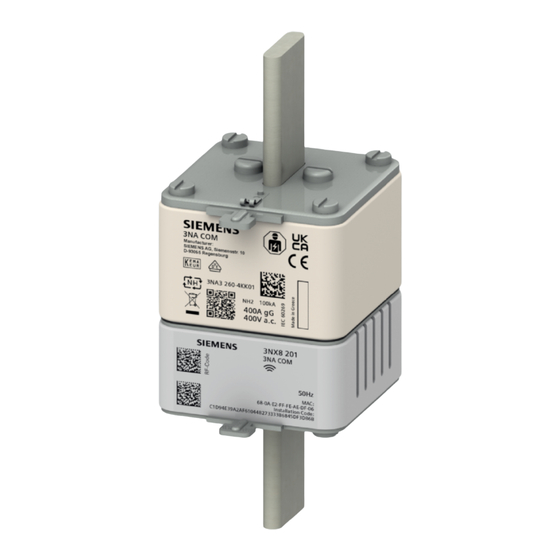
Circuit protection devices with communication and metering function 3.5 3NA COM fuse The measured values and states are wirelessly transmitted via the integrated communication and metering function. Thus, the final circuit can be monitored even further, by e.g. setting a limit value that sends a warning when a certain current or voltage value is exceeded. - Page 20 Circuit protection devices with communication and metering function 3.5 3NA COM fuse The 3NA COM fuse is available in size NH2 and operating class gG or gFF. It can be easily retrofitted in the existing fuse-disconnector due to its standard-compliant dimensions and auxiliary power.
-
Page 21: Installation And Connection
The country radio approvals are located in the SIOS portal. Simply search for the product or the order number and select the Certificates (https://support.industry.siemens.com/cs/de/en/) option as the type of contribution. Alternatively, these can also be accessed via the Siemens Industry Mall (https://mall.industry.siemens.com/mall/en/de/Catalog/Products/10005570?tree=CatalogTree) Circuit protection devices with communication and metering function... -
Page 22: Preparing Installation
Installation and connection 4.1 Preparing installation Preparing installation 4.1.1 Checking delivery Procedure 1. When you receive the delivery, check the packaging for visible damage in transit. 2. If you discover damage in transit, lodge a complaint with the carrier responsible. Have the carrier confirm the damage in transit immediately. -
Page 23: Identification Of Circuit Protection Devices
Installation and connection 4.1 Preparing installation 6. If the package contents are incomplete, damaged, or not exactly what was ordered, inform the responsible delivery service immediately. NOTICE Damaged device • Ensure that the damaged device is not installed and commissioned. •... -
Page 24: Manufacturer Identification
• Serial number These data are printed on the front or side of the device. An unlabeled Data Matrix Code is located on the device, this can be scanned using the Siemens Industry Online Support (SIOS) (https://new.siemens.com/global/en/products/software/mobile-apps/industry-online- support.html). This allows technical or graphical data to be displayed directly. -
Page 25: User Identification
Then the devices can be coupled with the 7KN Powercenter 1000 when assembly and connection are complete. Further information can be found in the Installation Manual (https://support.industry.siemens.com/cs/ww/en/view/109791805). Note This is particularly necessary for 3NA COM fuses because after installation, these are no longer accessible without shutting down the main circuit. -
Page 26: Installation Conditions
Installation and connection 4.1 Preparing installation 4.1.3 Installation conditions The installation devices can be installed on to any DIN rail in any installation position. The direction of incoming supply is arbitrary and can be set as a parameter for the miniature circuit breakers and arc fault detection devices. -
Page 27: Permitted Ambient Conditions
Installation and connection 4.1 Preparing installation If several 7KN Powercenter 1000 devices share the same radio channel, interferences may occur between the devices. To ensure that this does not happen, the expansion of the radio range can be reduced by lowering the transmit power. The minimum transmit power amounts to -18 dBm. -
Page 28: Device Installation
5SL6 COM miniature circuit breaker at temperatures > 30°C according to the respective configuration manual of the product family. See also Configuration Manual Miniature Circuit Breakers (https://support.industry.siemens.com/cs/ww/en/view/45302792) Configuration Manual Residual Protective Devices /Arc Fault Detection Devices (AFDDs) (https://support.industry.siemens.com/cs/ww/en/view/45303255) Configuration Manual Fuse Systems (https://support.industry.siemens.com/cs/ww/en/view/45314810) -
Page 29: Install 5St3 Com Auxiliary Switch And Fault Signal Contact
Installation and connection 4.2 Device installation 4.2.2 Install 5ST3 COM auxiliary switch and fault signal contact Prior to wiring, first mount the auxiliary switch/fault signal contact to the main unit or fasten together on to the DIN rail. This helps reduce the risk of injury. The 5ST3 COM auxiliary switch/fault signal contact must be connected or disconnected from the supply voltage lines when completely assembled. -
Page 30: The 5Sl6 Com Miniature Circuit Breaker And 5Sv6 Com Arc Fault Detection Device
Installation and connection 4.2 Device installation 4.2.3 The 5SL6 COM miniature circuit breaker and 5SV6 COM arc fault detection device Both devices are simply snapped on to the DIN rail. Example 5SV6 COM arc fault detection device: 4.2.4 Install 3NA COM fuse The 3NA fuse link can only be installed in an LV HRC fuse link holder together with the 3NX electronic module pushed on. -
Page 31: Connecting The Devices
Installation and connection 4.3 Connecting the devices The 3NA COM electronic module does not require a separate power connection. It supplies itself from the primary current via the current transformer according to the Energy Harvesting principle, however, it requires a minimum current of 5 A for this purpose. Note The gFF operating class is only approved for the Netherlands. -
Page 32: Connecting The 7Kn Powercenter 1000 And 5St3 Com Auxiliary Switch And Fault Signal Contact
Installation and connection 4.3 Connecting the devices 4.3.1 Connecting the 7KN POWERCENTER 1000 and 5ST3 COM auxiliary switch and fault signal contact NOTICE DIN rail mounting To avoid damage to property, mount the devices for connection firmly on to the DIN rail. The screwless plug-in terminals are designed for the insertion of two conductors so that a loop-through is possible via the terminals to other devices in the control cabinet (daisy chaining). - Page 33 Installation and connection 4.3 Connecting the devices To remove the cable, press on the slot of the terminal release with a 0.4 x 2.5 mm screwdriver, then the cables can be easily pulled out. For the data transceiver, the Ethernet cable (min. Cat5 F/UTP) must also be connected in addition to the supply voltage after the dummy plug has been removed.
-
Page 34: Connecting The 5Sl6 Com Miniature Circuit Breaker And 5Sv6 Com Arc Fault Detection Device
Installation and connection 4.4 Interfaces of the 7KN POWERCENTER 1000 4.3.2 Connecting the 5SL6 COM miniature circuit breaker and 5SV6 COM arc fault detection device If the devices are mounted on the DIN rail, the terminals and the leads are tightened using a screwdriver. -
Page 35: Bluetooth Interface
Installation and connection 4.4 Interfaces of the 7KN POWERCENTER 1000 4.4.2 Bluetooth interface The Bluetooth interface enables local access to the data of the 7KN Powercenter 1000 on site. This is the Bluetooth Low Energy 4.2 standard. However, data transmission performance can be significantly improved with Bluetooth Low Energy 5.1. -
Page 36: Radio Interface To The Devices
MAC address and installation code of the device. Alternatively, this information can be entered manually. A description of the procedure can be found in the Installation Manual (https://support.industry.siemens.com/cs/ww/en/view/109791805). Note Once the terminal device has been paired with the data transceiver, the installation code is encrypted and replaced so that each communication connection is separately encrypted. -
Page 37: Operation Of The Sentron Circuit Protection Devices
Installation and connection 4.5 Operation of the SENTRON circuit protection devices Operation of the SENTRON circuit protection devices The circuit protection devices with metering and communication function have different operating options in addition to the communication function. 5SL6 COM / 5SV6 COM 5ST3 COM POC 1000 Only the 3NA COM fuse has neither LEDs for status display nor operating options on the... - Page 38 Installation and connection 4.5 Operation of the SENTRON circuit protection devices Furthermore, in the case of the 5SV6 COM arc fault detection device a test tripping operation is carried out after a short button press (< 3 s). This triggers the internal self-test of the electronics and a tripping operation examines the tripping mechanism at the same time.
-
Page 39: Led Signaling Of The Sentron Circuit Protection Devices
Installation and connection 4.6 LED signaling of the SENTRON circuit protection devices LED signaling of the SENTRON circuit protection devices The circuit protection devices with metering and communication function can display different statuses with the LEDs. The 3NA COM fuse is an exception here as well; it has no LEDs. - Page 40 Installation and connection 4.6 LED signaling of the SENTRON circuit protection devices Both for exceeding limit values and for warnings when the end of service life is reached, there are parameters which can be set to adjust the threshold of the alarms or to switch off the alarm completely.
-
Page 41: Commissioning
Commissioning Note Only qualified personnel are permitted to install, commission or service the devices. • Wear the prescribed protective clothing. Observe the general equipment regulations and safety regulations for working with high-voltage installations (e.g. DIN VDE, NFPA 70E as well as national or international regulations). •... -
Page 42: Commissioning With Sentron Powerconfig App
Note An exact description on how to use the app can be found in the Installation Manual (https://support.industry.siemens.com/cs/ww/en/view/109791805). First the 7KN Powercenter 1000 data transceiver must be added. This can happen in the following ways: • WLAN searches if the 7KN Powercenter 1000 and the mobile device are located in the same network. - Page 43 Commissioning 5.1 Commissioning with SENTRON powerconfig app Then the communication-capable devices must be coupled with the 7KN Powercenter 1000. This is only possible if the devices are powered, contrary to the previous steps, which can also be carried out offline. Pairing can be carried out for each individual device or simultaneously for several devices.
- Page 44 Commissioning 5.1 Commissioning with SENTRON powerconfig app During commissioning, the devices display different statuses on the LEDs; these were explained in the Chapter LED signaling of the SENTRON circuit protection devices (Page 37). Upon completion of the commissioning process, all LEDs should be static green, i.e. the commutative circuit protection devices are fully functional.
-
Page 45: Commissioning With Sentron Powerconfig For Pc
Commissioning 5.2 Commissioning with SENTRON powerconfig for PC Commissioning with SENTRON powerconfig for PC Alternatively, the circuit protection devices with communication and metering function can also be (re)configured with the SENTRON powerconfig PC software. First the 7KN Powercenter 1000 must be added from the same network. Then the individual terminal devices must be added in the “Overview”... -
Page 46: Removing Devices
Commissioning 5.3 Removing devices Removing devices 5.3.1 Delete Added devices can be deleted from the list view of the project in the software. In the app, this can only take place in the project view via the gear icon to the right of a 7KN Powercenter 1000. -
Page 47: Decouple
Commissioning 5.3 Removing devices 5.3.2 Decouple The Decouple function can be used in the detailed view of the individual devices. In doing so, the terminal devices are decoupled from 7KN Powercenter 1000, similar to a long button press on the devices, except that the software function does not reset the communication information. -
Page 48: Replace
Commissioning 5.3 Removing devices 5.3.3 Replace In addition to decoupling, the Replace function can also be selected in the detailed view of the individual devices. To do so, a new device must be scanned which replaces the current devices. In addition, the old device is removed from the radio network and the parameters are transferred to the new device. -
Page 49: Summary Of 3Na Com Fuses With The Same Name
Commissioning 5.4 Summary of 3NA COM fuses with the same name Summary of 3NA COM fuses with the same name If several fuses are added, these are displayed together in the app. This is referred to as "Device Group". In order to summarize fuses in a device group, the plant identifier of the devices must match. The respective installation position / phase should be specified for each fuse. - Page 50 Commissioning 5.5 Import and Export Android Circuit protection devices with communication and metering function System Manual, 06/2021, L1V30827018B-01...
-
Page 51: Commissioning Several 7Kn Powercenter 1000
Commissioning 5.6 Commissioning several 7KN POWERCENTER 1000 Commissioning several 7KN POWERCENTER 1000 Note Only qualified personnel are permitted to install, commission or service the devices. Up to four 7KN Powercenter 1000 devices can be operated in parallel in one radio cell. Several data transceivers can also be used by increasing the distance of the devices among each other (or reduced signal strength) so that the devices do not disturb one another. - Page 52 Commissioning 5.6 Commissioning several 7KN POWERCENTER 1000 Note A specific order must be maintained during commissioning so that not all 7KN Powercenter 1000 devices radio on one channel at the same time, thus putting too much strain on the channel and causing data to be lost. This is because the more radio- capable stations there are, the greater the risk that individual data packages from the different stations will be lost.
-
Page 53: Time-Outs
Commissioning 5.7 Time-Outs Repeat Steps 2 to 4 until all devices have been paired with the different 7KN Powercenter 1000 devices. Note Due to the conditional disconnection possibility of 3NA COM fuses and 5ST3 COM auxiliary/fault signal contacts it is recommended to pair them with the first 7KN Powercenter 1000. -
Page 54: Use Of Third-Party Software
Commissioning 5.8 Use of third-party software Use of third-party software Both the SENTRON powerconfig, SENTRON powerconfig app and the SENTRON circuit protection devices with communication and metering function use third-party software licenses. These can be accessed in addition to the General Terms and Conditions. To do so, open •... -
Page 55: Functions
Functions The SENTRON circuit protection devices with communication and metering function offer different functions depending on the respectively recorded measured values and setting options. Recorded measured values and storage 6.1.1 Measured value acquisition The following measured values are recorded for the individual device types and e.g. displayed in the SENTRON powerconfig app in the device overviews. -
Page 56: Accuracy
Functions 6.1 Recorded measured values and storage 6.1.2 Accuracy The accuracy and measuring range of the individual measured values with a reference temperature of 23°C are described as follows: Measured value 5ST3 COM 5SL6 COM and 5SV6 COM 3NA COM Temperature ±2°C from -2°C ... -
Page 57: Measured Value Memory
Functions 6.1 Recorded measured values and storage 6.1.4 Measured value memory The different measured values are saved in the 7KN Powercenter 1000 and can be displayed in the trends of the respective devices in the SENTRON powerconfig app (not via Bluetooth). A distinction can be made between the following trends depending on whether the aforementioned measured value is supported by the respective device. -
Page 58: Messages
Functions 6.2 Messages Messages 6.2.1 Measured values and upper limit violation The following messages are possible due to upper limit violations: Possible message sources: Description Default POC 1000 5ST3 COM 5SL6 COM 5SV6 COM 3NA COM End of maximum set operating periods Inactive ✓... -
Page 59: Tripping Operations In The Event Of A Fault
Functions 6.2 Messages In addition to the messages that can be controlled by the user, listed in the table above, there are others events captured during operation, e.g. • Resetting the energy counter • Changing the time on the 7KN Powercenter 1000 •... - Page 60 Functions 6.2 Messages The 5ST3 COM auxiliary switch / fault signal contact communicates the status of the installed device. Thus, it distinguishes between a manual shutdown and a tripping operation due to error. The manual shutdown is displayed in the device overview and in the switching cycle counter.
-
Page 61: Time Synchronization
> 30 minutes. Messages remain intact with the appropriate time stamp of the entry. See also Manual - 7KN POWERCENTER 3000 (https://support.industry.siemens.com/cs/ww/en/view/109763838) How do you configure your PC as NTP server? (https://support.industry.siemens.com/cs/ae/en/view/22144502) Circuit protection devices with communication and metering function... -
Page 62: Modbus Tcp Connection
Functions 6.4 Modbus TCP connection Modbus TCP connection A 7KN Powercenter 1000 supports up to 3 Modbus TCP connections simultaneously via the Ethernet interface and 1 additional Bluetooth connection in parallel. This means that different software applications are able to communicate with the data transceiver. This however, is advised against. -
Page 63: Device Addressing Via Modbus Tcp
Functions 6.4 Modbus TCP connection 6.4.1 Device addressing via Modbus TCP 7KN Powercenter 1000 devices are addressed via their IP address and the device address. Even the paired, communication-capable terminal devices are individually addressed via their device address. The data can also be transmitted to higher-level systems. Note The information of the 7KN Powercenter 1000 is addressed with 255 (0xFF) in the Unit ID. - Page 64 Functions 6.4 Modbus TCP connection In the powerconfig PC version, the device addresses can be set in the communication view. If the Unit ID information is not available, a device can be identified by querying the identification parameters (order number, serial number and plant identification number) if all 24 possible unit IDs are checked.
-
Page 65: Protocol Information
Functions 6.4 Modbus TCP connection See also Messaging on TCP / IP Implementation Guide V1.0b (https://www.modbus.org/docs/Modbus_Messaging_Implementation_Guide_V1_0b.pdf) Modbus Application Protocol Specification V1.1b (https://modbus.org/docs/Modbus_Application_Protocol_V1_1b.pdf) 6.4.2 Protocol information Register addressing According to the Modbus specification the registers are numbered starting from 1 but addressed starting with 0. - Page 66 Functions 6.4 Modbus TCP connection Individual units of information are identified by register addresses. A register is 16 bits in size. If a unit of information is larger than 16 bits, it will require the corresponding number of registers. Example of the representation by means of a 32-Bit floating point number FP32 according to IEEE 754 Example of the representation of a 67-Bit floating point number FP67 according to IEEE 754 Example of the representation of a time stamp based on a FP64 number...
-
Page 67: Delayed Response And Parallel Accesses
Functions 6.4 Modbus TCP connection 6.4.3 Delayed Response and parallel accesses For many devices there is enough time to acknowledge the Modbus access within the required response time. The system however, usually composed of one 7KN Powercenter 1000 and the connected circuit protection devices, is a spatially distributed system. -
Page 68: Information Categories Of The Sentron Circuit Protection Devices
Functions 6.4 Modbus TCP connection 6.4.4 Information categories of the SENTRON circuit protection devices The metering and communication-capable SENTRON circuit protection devices have different categories of information. Many of these are common to all or many devices. There is also information that is specific for individual device types. -
Page 69: Information On Identification
6.4.4.1 Information on identification Regis- Length Designation Format Value range 5ST3 5SL6 5SV6 cess 1000 Manufacturer iden- 42 = Siemens tification Order number UCHAR[20] ASCII characters Serial number UCHAR[16] ASCII characters Hardware version (revision level) Software version UCHAR[4] ASCII characters... -
Page 70: Communication Parameters Ip
Functions 6.4 Modbus TCP connection 6.4.4.2 Communication parameters IP Regis- Length Designation Format Value range 5ST3 5SL6 5SV6 cess 1000 Ethernet MAC ad- uchar[6] dress DHCP on/off 0 = Off, 1 = On SNTP server IP ad- 0 … 0xFFFFFFFF dress SNTP client mode 0 = Off (default),... -
Page 71: Bluetooth Communication Parameters
Functions 6.4 Modbus TCP connection 6.4.4.3 Bluetooth communication parameters Regis- Lengt Designation Format Value range 5ST3 5SL6 5SV6 fault cess 1000 Bluetooth switch 1 = BLE switch on on/off or reset 2 = BLE switch off 3 = Passkey reset Bluetooth Status 0 = inactive 1 = connectable... -
Page 72: Communication Information Radio
Functions 6.4 Modbus TCP connection 6.4.4.5 Communication information radio Regis- Length Designation Format Value range 5ST3 5SL6 5SV6 cess 1000 1536 Install. Code de- UCHAR[18] 0xFFF... vice 1 1545 MAC address de- UCHAR[8] 0xFFF... vice 1 1549 Install. code device 0xFFF... -
Page 73: Measurement Settings
Functions 6.4 Modbus TCP connection Regis- Length Designation Value range Unit 5ST3 5SL6 5SV6 cess 1000 3102 Imported reactive FP64 Varh energy 3106 Exported reactive FP64 Varh energy 3110 Status of the 0 = Status un- mounted circuit known protection devices 1 = Breaker off, without trip- ping operation... - Page 74 Functions 6.4 Modbus TCP connection Reg- Length Designation For- Value Default Unit 5ST3 5SL6 5SV6 ister range cess 1000 3608 Limit value of FP32 0 … 150 upper current violation for Alarm2 in % of 3610 Hysteresis for FP32 0 … 10 upper current violation Alarm2 3616...
- Page 75 Functions 6.4 Modbus TCP connection Reg- Length Designation For- Value Default Unit 5ST3 5SL6 5SV6 ister range cess 1000 3652 Switching 0 = Off Alarm1 on and 1 = On off for lower voltage violation 3653 Limit value for FP32 150 …...
-
Page 76: Diagnostic Information
Functions 6.4 Modbus TCP connection 6.4.4.8 Diagnostic information Reg- Designation For- Value range Default Unit 5ST3 5SL6 5SV6 ister cess 1000 2560 Alarms status See table Alarms sta- tus details below. 2562 Operating FP64 hours with load current 2566 Switching the 0 = Off operating hours 1 = On... - Page 77 Functions 6.4 Modbus TCP connection Reg- Designation For- Value range Default Unit 5ST3 5SL6 5SV6 ister cess 1000 2604 Switching the 0 = Off trip violations 1 = On alarm on and 2605 Trip counter FP32 1 … 10000 limit value 2621 Bluetooth re- -127 ...
- Page 78 Functions 6.4 Modbus TCP connection Alarms status details (address 0x0A0): U32 - bit sequence Bit value Designation Value range Alarm operating hours with load current 0 = inactive, 1 = active Alarm operating hours 0 = inactive, 1 = active Alarm operating cycles 0 = inactive, 1 = active Alarm tripping operations...
-
Page 79: Application Examples
Application examples The SENTRON circuit protection devices with communication and metering function protect the final circuit and gather its data to increase system availability. The devices are used in a main or sub-distribution board. In doing so, the increased transparency allows predictive fault detection through early warnings or targeted, simplified maintenance through permanent status recording. - Page 80 LOGO! 8.3 or suitable systems. The information from the Chapter Modbus TCP Connection (Page 60) must be used for this purpose. See also Manual 7KN Powercenter 3000 (https://support.industry.siemens.com/cs/ww/en/view/109763838) SENTRON powermanager (https://support.industry.siemens.com/cs/ww/en/view/109771760) SENTRON powermind (https://support.industry.siemens.com/cs/ww/en/view/109793862) MindSphere (https://www.plm.automation.siemens.com/global/en/products/mindsphere/) Circuit protection devices with communication and metering function System Manual, 06/2021, L1V30827018B-01...
-
Page 81: Service And Maintenance
The firmware updates of all SENTRON circuit protection devices with communication and metering function are provided in the SIOS portal. The current firmware update can be found here (https://support.industry.siemens.com/cs/ww/en/view/109797242). Note A safe, signed update can only be carried out with the SENTRON powerconfig PC version. - Page 82 Service and maintenance 8.2 Firmware update Each communication-capable circuit protection device has the possibility of a firmware update. This can be carried out via the device menu. The updates are transferred to the 7KN Powercenter 1000 via the Ethernet cable. The terminal devices however, receive their update via wireless transmission from the 7KN Powercenter 1000.
-
Page 83: Disposal Of Waste Electronic Equipment
Service and maintenance 8.3 Disposal of waste electronic equipment Disposal of waste electronic equipment Disposal of waste electronic equipment Waste electronic equipment must not be disposed of as unsorted municipal waste, e.g. household waste. When disposing of waste electronic equipment, the current local national/international regulations must be observed. - Page 84 Service and maintenance 8.3 Disposal of waste electronic equipment Circuit protection devices with communication and metering function System Manual, 06/2021, L1V30827018B-01...
-
Page 85: Faqs
FAQs Error on commissioning Fault description Solutions The LEDs are not illuminated Check the power supply units. No 7KN Powercenter 1000 found in the list of • Check whether the mobile device activated Bluetooth and the GPS data available Bluetooth devices •... - Page 86 FAQs 9.1 Error on commissioning Fault description Solutions 7KN Powercenter 1000 no longer provides any • Check whether the mobile device is also connected to the same net- data after commissioning work as the 7KN Powercenter 1000 • Check whether the 7KN Powercenter 1000 has received another IP address, by carrying out the WLAN search again •...
-
Page 87: Error With Modbus Tcp Connection
FAQs 9.2 Error with Modbus TCP connection Error with Modbus TCP connection Fault description Solutions Devices not reachable • Check power supply (communication only possible if the device is supplied with power. If necessary, the device has tripped) • Check the correct device address •... - Page 88 FAQs 9.3 Error with firmware update Circuit protection devices with communication and metering function System Manual, 06/2021, L1V30827018B-01...
-
Page 89: Technical Specifications
Technical specifications 10.1 7KN POWERCENTER 1000 Designation Value Order number 7KN1110-0MC00 Product name 7KN Powercenter 1000 Execution of the housing Standard rail instrument Suitability for application 5ST3 COM, 5SL6 COM, 5SV6 COM, 3NA COM Number of supported devices Supply voltage DC 24 V SELV Minimum supply voltage at DC rated value 19.2 V... -
Page 90: 5St3 Com Auxiliary Switch And Fault Signal Contact
Technical specifications 10.2 5ST3 COM auxiliary switch and fault signal contact 10.2 5ST3 COM auxiliary switch and fault signal contact Designation Value Order number 5ST30620MC Product name 5ST3 COM auxiliary switch / fault signal contact Operating voltage rated value 24 V DC (SELV) Design of the product factory fitted Available measurement data Manual ON/OFF, tripping operation, temperature, switching... -
Page 91: 5Sl6 Com Miniature Circuit Breaker
Technical specifications 10.3 5SL6 COM miniature circuit breaker 10.3 5SL6 COM miniature circuit breaker Designation Value Order number 5SL60xx-yMC (xx = 02, 04, 06, 08, 10, 13, 16, 20, 25, 32; y = 6 or 7) Product name 5SL6 COM compact miniature circuit breaker Tripping characteristic class B and C Operational current for AC rated value... - Page 92 Technical specifications 10.3 5SL6 COM miniature circuit breaker Designation Value Product standard leading EN 60898-1 Supply voltage frequency rated value 50 Hz Power loss [W] (max.) Between 1 ... 5.7 W depending on rated current and charac- teristics Power loss [W] a rated value current with AC at warm oper- Between 0.9 ...
-
Page 93: 5Sv6 Com Arc Fault Detection Device
Technical specifications 10.4 5SV6 COM arc fault detection device Designation Value Measurable line frequency initial value 45 Hz Power consumption of the power supply 0.4 VA Measuring category for voltage measurement CAT III acc. to IEC 61010-2-030 Minimum measurable current at AC 0.04 A Maximum measurable current at AC 2 x I... - Page 94 Technical specifications 10.4 5SV6 COM arc fault detection device Designation Value Minimum connectable conductor cross-section, finely 0.75 mm stranded with end sleeve Minimum tightening torque 1.2 N.m Maximum tightening torque 2 N.m Pollution degree Minimum ambient temperature during storage -40°C Maximum ambient temperature during storage 75°C Maximum ambient temperature during operation...
-
Page 95: 3Na Com Fuse
Technical specifications 10.5 3NA COM fuse Designation Value Minimum measurable mains voltage between N and L 50 V Measurable line frequency final value 60 Hz Measurable line frequency initial value 45 Hz Power consumption of the power supply 0.4 VA Measuring category for voltage measurement CAT III acc. - Page 96 Technical specifications 10.5 3NA COM fuse Designation Value Power supply CT Harvesting Reference ID in accordance with DIN EN 61346-2 Reference ID in accordance with IEC 81346-2:2009 Design of the indicator Front indicator Mounting type Non-insulated grip lugs Design of the switching contact Non-corroding, silver-plated Mounting position Any, preferably vertical...
-
Page 97: Dimension Drawings
Dimension drawings 11.1 7KN POWERCENTER 1000 Dimensions in mm Circuit protection devices with communication and metering function System Manual, 06/2021, L1V30827018B-01... -
Page 98: 5St3 Com Auxiliary Switch And Fault Signal Contact
Dimension drawings 11.2 5ST3 COM auxiliary switch and fault signal contact 11.2 5ST3 COM auxiliary switch and fault signal contact Dimensions in mm Circuit protection devices with communication and metering function System Manual, 06/2021, L1V30827018B-01... -
Page 99: 5Sl6 Com / 5Sv6 Com Miniature Circuit Breaker And Arc Fault Detection Device
Dimension drawings 11.3 5SL6 COM / 5SV6 COM miniature circuit breaker and arc fault detection device 11.3 5SL6 COM / 5SV6 COM miniature circuit breaker and arc fault detection device Dimensions in mm Circuit protection devices with communication and metering function System Manual, 06/2021, L1V30827018B-01... -
Page 100: 3Na Com Fuse
Dimension drawings 11.4 3NA COM fuse 11.4 3NA COM fuse Dimensions in mm Circuit protection devices with communication and metering function System Manual, 06/2021, L1V30827018B-01... -
Page 101: Circuit Diagrams
Circuit diagrams 12.1 7KN POWERCENTER 1000 Circuit protection devices with communication and metering function System Manual, 06/2021, L1V30827018B-01... -
Page 102: 5St3 Com Auxiliary Switch And Residual Current Switch
Circuit diagrams 12.2 5ST3 COM auxiliary switch and residual current switch 12.2 5ST3 COM auxiliary switch and residual current switch 12.3 5SL6 COM miniature circuit breaker Circuit protection devices with communication and metering function System Manual, 06/2021, L1V30827018B-01... -
Page 103: 5Sv6 Com Arc Fault Detection Device
Circuit diagrams 12.4 5SV6 COM arc fault detection device 12.4 5SV6 COM arc fault detection device 12.5 3NA COM fuse Circuit protection devices with communication and metering function System Manual, 06/2021, L1V30827018B-01... - Page 104 Circuit diagrams 12.5 3NA COM fuse Circuit protection devices with communication and metering function System Manual, 06/2021, L1V30827018B-01...
-
Page 105: Esd Guidelines
ESD guidelines Electrostatic sensitive devices (ESD) ESD components are destroyed by voltage and energy far below the limits of human perception. Voltages of this kind occur as soon as a device or an assembly is touched by a person who is not electrostatically discharged. ESD components which have been subject to such voltage are usually not recognized immediately as being defective, because the malfunction does not occur until after a longer period of operation. - Page 106 ESD guidelines A.1 Electrostatic sensitive devices (ESD) ESD seat ESD standing position ESD seat and ESD standing position Protective measures Conductive floor ESD table ESD footwear ESD smock ESD bracelet Cubicle ground connection Circuit protection devices with communication and metering function System Manual, 06/2021, L1V30827018B-01...
-
Page 107: List Of Abbreviations
List of abbreviations Abbreviations AFDD Arc Fault Detection Device Delayed Acknowledge DHCP Dynamic Host Configuration Protocol Data Matrix Code Miniature Circuit Breaker Radio Frequency RSSI Received Signal Strength Indicator Rated current Rated voltage Circuit protection devices with communication and metering function System Manual, 06/2021, L1V30827018B-01... - Page 108 List of abbreviations Circuit protection devices with communication and metering function System Manual, 06/2021, L1V30827018B-01...
-
Page 109: Index
Index Delivery Checking, 20 Description 3NA COM fuse, 18 3NA COM fuse 5SL6 COM miniature circuit breaker, 16 Description, 18 5ST3 COM auxiliary switch and residual current Mounting, 28 switch, 15 5SV6 COM arc fault detection device, 17 7KN POWERCENTER 1000, 15 Discharge, 103 5SL6 COM miniature circuit breaker Description, 16... - Page 110 Index Open Source Software, 10 Use, 10 Pairing Commissioning, 51 Radio interface, 34 Security functions, 9 Storage, 103 Technical Support, 7 Third-party software, 52 Time-Out, 51 Training, 8, 8 Learning paths, 8 WBT, 8 Transmission frequency Measured value, 54 Transport, 103 User identification, 23 Training, 8 WBT –...