
Related Manuals for Toro Pro Force Debris


Summary of Contents for Toro Pro Force Debris
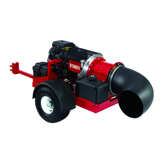
- Page 1 Form No. 3438-217 Rev B Pro Force ® Debris Blower Model No. 44552—Serial No. 405800000 and Up Model No. 44552TE—Serial No. 405800000 and Up *3438-217* B Register at www.Toro.com. Original Instructions (EN)
- Page 2 Operation is subject to the following two conditions: (1) this device may not cause interference, and (2) this device must accept any interference, including interference that may cause undesired operation of the device. © 2020—The Toro® Company Contact us at www.Toro.com. 8111 Lyndale Avenue South Printed in the USA...
- Page 3 Important calls attention to special mechanical additional information, contact an Authorized Service information and Note emphasizes general information Dealer or Toro Customer Service and have the model worthy of special attention. and serial numbers of your product ready. Figure 1 identifies the location of the model and serial numbers on the product.
-
Page 4: Table Of Contents
Contents Adjusting the Belt..........29 Miscellaneous Maintenance......... 29 Checking the Blower Nozzle ......29 Safety ............... 5 Associating the Remote Control and the General Safety ........... 5 Base Unit ............. 30 Safety and Instructional Decals ......6 Storage ..............31 Setup ................ -
Page 5: Safety
Safety This machine has been designed in accordance with ANSI standard B71.4-2017. General Safety This product is capable of throwing objects. Always follow all safety instructions to avoid serious personal injury. • Read and understand the contents of both this Operator’s Manual and the operator’s manual of the traction unit before using this machine. -
Page 6: Safety And Instructional Decals
Safety and Instructional Decals Safety decals and instructions are easily visible to the operator and are located near any area of potential danger. Replace any decal that is damaged or missing. decal115-5105 115-5105 1. Warning—read the Operator's Manual. 2. Warning—all operators should read the Operator’s Manual and be trained before operating the machine. 3. -
Page 7: Setup
Determine the left and right sides of the machine from the normal operating position. Connecting the Battery Parts needed for this procedure: — Grafo 112X grease (Toro Part No. 505-47) Procedure g029816 Figure 3 Remove the clips securing the battery cover to 1. -
Page 8: Mounting The Hitch To The Debris Blower
1. Frame brackets 3. Hitch clevis Coat the terminals and mounting fasteners with 2. Hitch tube Grafo 112X (skin over) grease (Toro Part No. 505-47) to prevent corrosion. Note: The hitch tube can be rotated 180 Install the battery cover and secure with the degrees to accommodate different hitch heights. -
Page 9: Assembling The Handheld Remote
If the blower contacts the tow vehicle when turning, the hitch tube does not extend enough and needs to be installed to the frame brackets using the further mounting holes; refer to Mounting the Hitch to the Debris Blower (page Connect the blower clevis hitch to the tow vehicle hitch with the hitch pin and clevis (Figure... -
Page 10: Product Overview
Choke Control Product Overview To start a cold engine, move the choke control lever (Figure 8) to the O position. Controls Engine Stop Press the Engine Stop button to shut off the engine (Figure g029819 Figure 8 3. Ignition switch 1. -
Page 11: Specifications
Authorized Service Dealer or authorized Toro functioning properly. distributor or go to www.Toro.com for a list of all • Ensure that the traction unit is suitable for use with approved attachments and accessories. -
Page 12: Adding Fuel
Adding Fuel Filling the Fuel Tank Shut the engine off. • Fuel tank capacity: 18.9 L (5 US gallons) Clean the area around the fuel tank cap and • Recommended Fuel remove the cap (Figure 10). – For best results, use only clean, fresh (less Note: The fuel tank cap contains a gauge which than 30 days old), unleaded fuel with an octane... -
Page 13: Checking The Tire Pressure
Checking the Tire Pressure During Operation Check the tire pressure (Figure 11). During Operation Safety The correct tire pressure is 96.5 kPa (14 psi). General Safety • The owner/operator can prevent and is responsible for accidents that may cause personal injury or property damage. -
Page 14: Remote Control Operation
Remote Control Operation • Reduce speed when operating on rough, uneven terrain, and near curbs, holes, and other sudden • Failure to abide by the safety precautions may changes in terrain. result in equipment failure, loss of authority to • To avoid causing the machine to tip over, be operate the equipment, and personal injury. -
Page 15: Starting The Engine
Starting the Engine WARNING Rotating parts can cause serious personal injury. • Keep your hands, feet, hair, and clothing away from all moving parts to prevent injury. • Never operate the machine with covers, shrouds, or guards removed. g029818 Ensure that the blower is attached to the tow Figure 13 vehicle before you start the blower. -
Page 16: Shutting Off The Engine
• between attempts. Failure to follow these When in the time-out mode the engine does not instructions can burn out starter motor. run (or quits running) and the remote control does not control any function. After the engine starts, move the choke control to •... -
Page 17: Using The Chute Position Indicator
Using the Chute Position Important: Raise the blower nozzle before transporting the blower. If you leave the blower Indicator nozzle in the down position during transport, it may contact the ground and become damaged. When the green indicator tab is visible in the rotation gauge window, the chute is positioned on the left side. -
Page 18: After Operation
Hauling After Operation • Use care when loading or unloading the machine into a trailer or truck. After Operation Safety • Use full-width ramps for loading machine into trailer or truck. General Safety • Tie the machine down securely using straps, •... -
Page 19: Maintenance
Determine the left and right sides of the machine from the normal operating position. Note: Download a free copy of the electrical or hydraulic schematic by visiting www.Toro.com and searching for your machine from the Manuals link on the home page. -
Page 20: Recommended Maintenance Schedule(S)
Recommended Maintenance Schedule(s) Maintenance Service Maintenance Procedure Interval • Check the condition and the tension of the belt. After the first 8 hours • Check the torque of the wheel lug nuts. After the first 10 hours • Check the engine oil level. •... -
Page 21: Engine Maintenance
Engine Maintenance Separate the air-filter cover from the air-filter housing, and clean the inside of the cover (Figure 17). Engine Safety Gently slide the air-filter element out of the filter housing. • Shut off the engine before checking the oil or adding oil to the crankcase. -
Page 22: Servicing The Carbon Canister
Secure the cover to the housing with the latches (Figure 17). Servicing the Carbon Canister Replacing the Carbon Canister Air Filter Service Interval: Every 200 hours Shut off the engine, remove the key, and wait for all moving parts to stop before leaving the operating position. - Page 23 Checking the Engine-Oil Level Shut off the engine, remove the key, and wait for all moving parts to stop before leaving the Service Interval: Before each use or daily operating position. Note: The best time to check the engine oil is when Place a pan below the drain.
-
Page 24: Servicing The Spark Plugs
g001056 Figure 23 1. Oil filter 3. Adapter 2. Adapter gasket Apply a thin coat of new oil to the rubber gasket on the replacement filter (Figure 23). Install the replacement oil filter to the filter adapter, turn the oil filter clockwise until the rubber gasket contacts the filter adapter, then tighten the filter an additional 2/3 to 1 turn (Figure... -
Page 25: Cleaning The Engine Screen And The Oil Cooler
Checking the Spark Plugs Clean around the spark plugs to prevent dirt from falling into the engine and potentially Service Interval: Every 200 hours causing damage. Look at the center of the spark plugs (Figure 24). Remove the spark plugs and the metal washers. If you see light brown or gray on the insulator, the engine is operating properly. -
Page 26: Fuel System Maintenance
Servicing the Fuel Tank Fuel System Maintenance DANGER In certain conditions, fuel is extremely Replacing the Fuel Filter flammable and highly explosive. A fire or explosion from fuel can burn you and others Service Interval: Every 500 hours and can damage property. Never install a dirty filter if it is removed from the fuel •... -
Page 27: Electrical System Maintenance
Replacing the Remote Electrical System Batteries Maintenance The handheld remote is powered by 4 AAA batteries. Important: Before welding on the machine, When installing batteries, be sure to observe proper disconnect the controller and the negative polarity as marked on the inside of the compartment to cable from the battery to prevent damage to the avoid damaging the unit. -
Page 28: Replacing The Fuses
Replacing the Fuses Drive System Maintenance Engine A 15 A in-line fuse is incorporated into the engine wire harness (Figure 29). Inspecting the Tires Service Interval: Every 100 hours Check the tire pressure frequently to ensure proper inflation (241 kPa or 35 psi). If the tires are not inflated to the correct pressure, the tires will wear prematurely. -
Page 29: Belt Maintenance
Belt Maintenance Miscellaneous Maintenance Adjusting the Belt Checking the Blower Nozzle Service Interval: After the first 8 hours Every 50 hours Service Interval: Before each use or daily If the belt slips when changing the direction of the blower nozzle, an adjustment to the belt is required. Checking the Blower Nozzle Loosen the bolts securing the pulley mounting Clamp... -
Page 30: Associating The Remote Control And The Base Unit
Release the buttons. Press and hold the R button. The OTATE LED will blink about twice per second. Continue holding the R button and OTATE turn the key start to the R position. The LED turns solid if the procedure is successful. Note: This could take up to 20 seconds. -
Page 31: Storage
Storage into the spark plug hole. Now use the starter to crank the engine and distribute the oil inside the cylinder. Install the spark plug(s). Do not install Storing the Machine the wire on the spark plug(s). Check and tighten all fasteners. Repair or Park the machine on a level surface, shut off the replace any part that is damaged or missing. -
Page 32: Troubleshooting
There is a problem in the wiring; contact your authorized Toro distributor. BASE is bad; contact your authorized Toro Distributor. Blink once, pause, blink twice, Version incompatibility of The software installed is not correct. Install the correct... -
Page 33: Resetting The Fault Codes
Resetting the Fault Codes After solving the problem, set the ignition key to the R position and then disconnect and reconnect the diagnostic connectors. The diagnostic light will flash continuously once per second. Exiting Diagnostic Mode Turn the key to the O position to turn off the power. - Page 34 The Toro Company (“Toro”) respects your privacy. When you purchase our products, we may collect certain personal information about you, either directly from you or through your local Toro company or dealer. Toro uses this information to fulfil contractual obligations - such as to register your warranty, process your warranty claim or to contact you in the event of a product recall - and for legitimate business purposes - such as to gauge customer satisfaction, improve our products or provide you with product information which may be of interest.
- Page 35 While the exposure from Toro products may be negligible or well within the “no significant risk” range, out of an abundance of caution, Toro has elected to provide the Prop 65 warnings. Moreover, if Toro does not provide these warnings, it could be sued by the State of California or by private parties seeking to enforce Prop 65 and subject to substantial penalties.
- Page 36 Countries Other than the United States or Canada Customers who have purchased Toro products exported from the United States or Canada should contact their Toro Distributor (Dealer) to obtain guarantee policies for your country, province, or state. If for any reason you are dissatisfied with your Distributor's service or have difficulty obtaining guarantee information, contact your Authorized Toro Service Center.