Table of Contents
Advertisement
Quick Links
Advertisement
Table of Contents

Related Manuals for Lightmed LightLink-CXL


Summary of Contents for Lightmed LightLink-CXL
- Page 1 Service Manual LightLink - CXL Corneal Cross-Linking System...
- Page 2 Service Manual for the LightLink - CXL Corneal Cross-Linking System Directive 93/42/EEC as amended by 2007/47/EC Doc. No. : DCX002 Rev. No. : 01...
- Page 3 Linking System Technician or Engineer should ensure that they are adequately trained and understood in the procedures that the LightLink-CXL Corneal Cross-Linking System prior to operating or repairing the equipment. CAUTIONS - Use of controls or adjustments or performance of procedures other than those specified herein may result in hazardous radiation exposure.
- Page 4 Document Title: Preliminary Service Manual for the LightLink-CXL Corneal Cross-Linking System Document Number: DCX002 Document Revision History: DRAFT Sep 2012 Draft prepared Aug 2014 New release LightLink-CXL – Service Manual Rev. No. : 01 Page 3 of 98...
-
Page 5: Table Of Contents
A. Microprocessor PCB Replacment ............47 B. Aiming Module Replacement ..............49 C. Detector PCB Replacement ..............51 D. Backlight PCB Replacement ..............52 E. Aperture Motor Ass'y Replacement ............53 F. CCD Camera Replacement ...............54 LightLink-CXL – Service Manual Rev. No. : 01 Page 4 of 98... - Page 6 Software Installation Procedures ................ 88 A. Window 7.0 or Above...................88 B. Window XP....................92 10.5 Configuration Procedures ..................94 10.6 Downloading Procedures ..................96 Section 11 WARRANTY TERMS ................98 LightLink-CXL – Service Manual Rev. No. : 01 Page 5 of 98...
- Page 7 LIST OF DRAWINGS / FIGURES Figure Description Page Whole System Packaging Carton Packaging Label LightLink-CXL Corneal Cross-Linking System Breakdown Wheel Stopper Location LCD Ass’y latching releasing process 1 LCD Ass’y latching releasing process 2 LCD Ass’y latching process 1 LCD Ass’y latching process 2...
- Page 8 One aiming spot in detector 7.22 VR Location For Aiming Energy 7.23 7.24 CCD Camera with Aiming on the screen CCD Camera alignment Screws 7.25 CCD Camera Alignment Completion 7.26 LightLink-CXL – Service Manual Rev. No. : 01 Page 7 of 98...
- Page 9 Record Sheet Installation Record Sheet Power Parameter Calibration Record Sheet Detector Parameter Calibration Record Sheet Spot Size Power Calibration Record Sheet Aiming Power Calibration Record Sheet LightLink-CXL – Service Manual Rev. No. : 01 Page 8 of 98...
-
Page 10: Introduction
Any service work carried out by unauthorized persons will void all warranties. No circuit diagrams or component part lists are to be supplied for the LightLink-CXL. If you require technical documentation that is not provided in this manual then please contact the manufacturer or your local distributor in writing with your reasons for wanting them and then a copy of the service manual may be provided. -
Page 11: Safety
The LightLink-CXL Corneal Cross-Linking System is classified as a Class II device according to the FDA CFR21 regulations. The LightLink-CXL Corneal Cross-Linking System is classified as a Class II Type B Medical Device according to the MDD 93/42/EEC (as amended by 2007/47/EC). -
Page 12: Warnings And Precautions
IEC62471(2007) Warnings and Precautions The following warnings and precautions apply to the LightLink-CXL System and should be observed by all users at all time: DO NOT try to service or repair the system other than what is included in this manual. -
Page 13: User Safety
It is essential to use protective glasses to prevent the spread of UV light. Check with the Technical Assistance of LightMed in case of doubts. It must be dispensed special attention to avoid that the reflected light in mirrored surfaces hit the eye accidentally. -
Page 14: Patient Safety
We do not recommend the equipment use in places with gases, anesthetics or flammable liquids that could hit the equipment. Consult the LightMed technical support team in case of doubt LightMed Corporation does not take responsibility, directly or indirectly, for property damage, personal injury or financial losses that may occur due to the inappropriate use of this equipment, and the user is accountable for taking all the precautions listed. -
Page 15: Product Specifications
Section 3 PRODUCT SPECIFICATIONS The following are the System Specifications for the The LightLink-CXL Corneal Cross- Linking System . UV LIGHT WAVELENGTH 365nm ± 5nm UV LIGHT SOURCE UV LED Cluster System MAX. POWER RANGE Factory Limited 30mW/cm IRRADIANCE Adjustable: mW/cm²... - Page 16 Cooling System Optional Accessories The following accessory can be purchased from the Distributor to use with LightLink-CXL Corneal Cross-Linking System UV light Product. It is only available for customers outside the EU Countries due to the requirements for CE Marking. The manufacturer does not have controlled over the use of the attachments that are available and their indications for use.
-
Page 17: System Setup
Introduction and Requirements It is strongly recommended that the manufacturer or its authorized agent install the LightLink-CXL Corneal Cross-Linking System at the operator site to ensure that the system is operating correctly, aligned and calibrated according to specification. After this initial installation it is the operator’s responsibility to ensure the UV light system is operating correctly whenever the UV light is moved or relocated. -
Page 18: Unpacking And Receiving Inspection
LightLink-CXL Model : Serial Number : Manufactured : Manufactured By : XL0000 LightMed Corporation, No.1-1, Lane 1, Pao-An St. Sec. 3, Shulin City, Taipei, TAIWAN, R.O.C. 238 TEL : 886-2-2688-1726 FAX : 886-2-2688-5875 E-mail : sales@lightmed.com This device complies to the requirements of 21CFR . -
Page 19: Tools And Equipment
The motorized table is an optional and may be purchased from the manufacturer. Tools and Equipment In order to be able to effectively carry out a full initial installation of the LightLink-CXL Corneal Cross-Linking System the following tools and equipment are required and available from the manufacturer: 1. -
Page 20: Setting Up The Uv Light System Parts
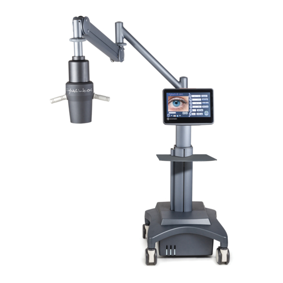
Swing UV Arm UV light Head UV light Arm LCD Touch Base Wheel & Control Box Screen UV light Head Figure 4.3 LightLink-CXL Corneal Cross-Linking System Breakdown LightLink-CXL – Service Manual Rev. No. : 01 Page 19 of 98... -
Page 21: Reassembling Process
Roll out the base wheel & control box and station it over well level ground Lock up the wheel station two stoppers (refer to fig. 4.4) Wheel stopper Figure 4.4 Wheel Stopper Location LightLink-CXL – Service Manual Rev. No. : 01 Page 20 of 98... - Page 22 Latch head pulling backward Figure 4.5 LCD Ass’y latching releasing process 1 Figure 4.6 LCD Ass’y latching releasing process 2 LightLink-CXL – Service Manual Rev. No. : 01 Page 21 of 98...
- Page 23 Take released latch LCD and gently slide against the mounting bracket and lock the latch when it is through Mounting Bracket Figure 4.7 LCD Ass’y latching process 1 Figure 4.8 LCD Ass’y latching process 2 LightLink-CXL – Service Manual Rev. No. : 01 Page 22 of 98...
- Page 24 Note: By doing this process will allow the arm ass’y and base wheel ass’y are closer and easily to slide in the arm ass’y Pressurized button Figure 4.10 Elevation Process LightLink-CXL – Service Manual Rev. No. : 01 Page 23 of 98...
- Page 25 Gently glide in over the wheel base and ensure the no tangle or jam in the wiring Cover the cap Figure 4.12 Wiring Clearances and End Cap Assembling LightLink-CXL – Service Manual Rev. No. : 01 Page 24 of 98...
- Page 26 Note: The height can be determine on the user preference but once secured the tray top will remain the adjusted height and can’t longer adjustable until it reset it again Height will be fixed once secured Figure 4.13 Tray Table Assembling LightLink-CXL – Service Manual Rev. No. : 01 Page 25 of 98...
- Page 27 Figure 4.14 Four Screws Removing Process Leave this side hanging over the laser arm Figure 4.15 UV head Holding Note: Do not let goes of holder before securing the UV holder LightLink-CXL – Service Manual Rev. No. : 01 Page 26 of 98...
- Page 28 Ensure the stopper is always locked prior for any swing integrity test Stopper lock (Always at lower position) Figure 4.16 UV Head Holder Securing Process LightLink-CXL – Service Manual Rev. No. : 01 Page 27 of 98...
- Page 29 Figure 4.17 UV Head Connection Take the two upper laser cover ass’y and gently assemble over the laser arm with four screws Figure 4.19 Upper Laser Cover Assembling LightLink-CXL – Service Manual Rev. No. : 01 Page 28 of 98...
- Page 30 Now the system is fully installed and ready to initial the testing Figure 4.20 System is Ready LightLink-CXL – Service Manual Rev. No. : 01 Page 29 of 98...
-
Page 31: Final Verification / Checkout
- Power on the LCD and await for the boot up process to be complete - Validate if there is software program is properly boot up (refer to below figure) - Validate if the camera integrity is ok LightLink-CXL – Service Manual Rev. No. : 01 Page 30 of 98... - Page 32 - Engage the aiming intensity to see if the aiming spots are evenly distributed - Proceed to calibration process if not valid (refer to section 7 on page 72) LightLink-CXL – Service Manual Rev. No. : 01 Page 31 of 98...
- Page 33 The Aiming beam is visible and intensity is adjustable. Installers Name : _____________________ Date: __________________ Distributor Name: ______________________ Date: __________________ Customer Name : ______________________ Date: __________________ (Send this Installation Report to the Manufacturer immediately.) LightLink-CXL – Service Manual Rev. No. : 01 Page 32 of 98...
-
Page 34: System Overview
System Overview General Operating Theory LightLink-CXL Corneal Cross-linking System is a specialized Ophthalmic Medical Device controlled by sophisticated PC embedded software integrated with the system. The system emits a low level UV-A light of 365nm, produced by the UV LED (Light Emitting Diode) Cluster, through a specialized Optical Module producing a homogeneous spot size and power controllable beam, intended for delivery on Corneal Surface. -
Page 35: Theory Of Operation
LCD Control Panel Ass’y It provides the interface between the laser system and user. This is where all the controls are located. It is done through the embedded system software. LightLink-CXL – Service Manual Rev. No. : 01 Page 34 of 98... -
Page 36: System Subassemblies
Webcam LED Lamp Micro Aiming Diode Controller Controller Interlock 365 UV LED Motor Controller Power Power UV LED Supply Supply Detector Mains Figure 5.1 System Block Diagram Overview LightLink-CXL – Service Manual Rev. No. : 01 Page 35 of 98... -
Page 37: Laser Head Ass'y
(CN7) (CN3) 11. Aperture Motor Connector 12. Power Energy Gain Adjuster (CN9) (VR3) 13. Software Download Connector 14. CPU Chips (JP1) (U1) 15. Buzzer (BZ1) Figure 5.3 Legends LightLink-CXL – Service Manual Rev. No. : 01 Page 36 of 98... - Page 38 If the laser is unable to function properly or has no output, then confirm if there is 24 VDC across the ZD1 or CN1 connector or TP11 and TP17 for the digital output signal of 5VDC. LightLink-CXL – Service Manual Rev. No. : 01 Page 37 of 98...
-
Page 39: Aiming Module
The buzzer is also built in the CPU PCB located in lower left quadrant. CN6 is used to connect the 'Interlock key'. CN8 is the connection for CCD camera and backlight LED. B. Aiming Module LightLink-CXL – Service Manual Rev. No. : 01 Page 38 of 98... - Page 40 CPU PCB through two VRs (VR1 and VR2). The intensity is range from 0 to 600 The voltage is proportional to intensity. The intensity is divided into 10 segment bar graph. LightLink-CXL – Service Manual Rev. No. : 01 Page 39 of 98...
-
Page 41: Ccd Camera
CCD camera is USB plug-in device and the applied voltage is +5VDC and the current consumption is 0.5A. The CCD camera position can be realigned through the four set screws. More detailed you may refer to the realignment process on page 79. LightLink-CXL – Service Manual Rev. No. : 01 Page 40 of 98... -
Page 42: Aperture Motor Ass'y
The motor applied voltage is +/- 12VDC. The motor ass'y has current limited protection of 60 mA so if there is any over current incident, the system will shut it down. LightLink-CXL – Service Manual Rev. No. : 01 Page 41 of 98... -
Page 43: Backlight Led
This white backlight LED is used to assist the doctor to see the treatment area much more clearly. The applied voltage is +12 VDC. The LED intensity is driven by current. The max current limitation is 40mA. LightLink-CXL – Service Manual Rev. No. : 01 Page 42 of 98... -
Page 44: Detector Pcb
Figure 5.9 Detector Ass’y This detector is used to feedback the laser output power to MCU so it will recalculate if the power gain is correctly. The applied voltage is +5VDC. LightLink-CXL – Service Manual Rev. No. : 01 Page 43 of 98... -
Page 45: Power Control Box
It is an auto-ranging power supply module. The input main voltage can be ranged from 90 to 240 AC volts. The output voltage is +12 VDC. LightLink-CXL – Service Manual Rev. No. : 01 Page 44 of 98... -
Page 46: Lcd Power Supply
This software platform provides an interface between the user and console system. More screen operation control are detailed or explained in the operator manual section 4 on page 22. LightLink-CXL – Service Manual Rev. No. : 01 Page 45 of 98... -
Page 47: Repairing Procedures
Before removing any module part ensure the power is always turned off and power cord disconnected. Ensure the statics wrist band is always worn prior to removing any laser diodes since they are static sensitive components. LightLink-CXL – Service Manual Rev. No. : 01 Page 46 of 98... -
Page 48: Microprocessor Pcb Replacment
3. Remove the three screws by using 2.0mm Allen key 4. Gently and slowly remove the PCB down Note: Do remember to tag all the connectors First screw Other two screws Figure 6.1 UV head PCB LightLink-CXL – Service Manual Rev. No. : 01 Page 47 of 98... - Page 49 3. Ensure there is no loosen connections and close up the cover top 4. Power on and validate the system performance refer to section 4.6 on page 31 LightLink-CXL – Service Manual Rev. No. : 01 Page 48 of 98...
-
Page 50: Aiming Module Replacement
4. Gently and slowly remove the laser diode and holder Note: Do remember to tag all the connectors Set screw Figure 6.3 Aiming set screw Two aiming connectors Figure 6.4 Aiming connectors LightLink-CXL – Service Manual Rev. No. : 01 Page 49 of 98... - Page 51 3. Ensure there is no loosen connections and close up the cover top 4. Power on and validate the system performance and recalibrate it if required refer to section 7 on page 72 LightLink-CXL – Service Manual Rev. No. : 01 Page 50 of 98...
-
Page 52: Detector Pcb Replacement
5. Ensure there is no loosen connections and close up the cover top 6. Power on and validate the system performance refer to section 4.6 on page 31 7. Recalibrate the Power and Detector parameter (refer to recalibration procedures) LightLink-CXL – Service Manual Rev. No. : 01 Page 51 of 98... -
Page 53: Backlight Pcb Replacement
3. Ensure there is no loosen connections and close up the cover top 4. Power on and validate the system performance refer to section 4.6 on page 31 LightLink-CXL – Service Manual Rev. No. : 01 Page 52 of 98... -
Page 54: Aperture Motor Ass'y Replacement
Note: Do remember to reconnect all connectors before turning on the power 4. Ensure there is no loosen connections and close up the cover top Power on and validate the system performance refer to section 7 on page 60 LightLink-CXL – Service Manual Rev. No. : 01 Page 53 of 98... -
Page 55: Ccd Camera Replacement
6. Loosen nut at front side and take connect off Note: This step must take all the connector off in addition to aiming connector Two screws and wirings Figure 6.8 CCD Camera Replacement LightLink-CXL – Service Manual Rev. No. : 01 Page 54 of 98... - Page 56 Note: Do remember to reconnect all connectors before turning on the power 5. Ensure there is no loosen connections and close up the cover 6. Power on and validate the system performance refer to section 7 on page 79 LightLink-CXL – Service Manual Rev. No. : 01 Page 55 of 98...
-
Page 57: Calibration Procedures
Safety Goggle (for this specified system) VR pot adjuster or small flat screw driver Note: Do remember to remove the front cover before any realignment process takes place LightLink-CXL – Service Manual Rev. No. : 01 Page 56 of 98... - Page 58 - Restart the main program again by click the software program in startup menu Double clicks to initial the software Figure 7.2 The software position in Main Program LightLink-CXL – Service Manual Rev. No. : 01 Page 57 of 98...
- Page 59 Figure 7.3 A hidden icon at the left top corner on screen Motor Parameter Icon Figure 7.4 Main page of Calibration Mode - Press the "Motor Parameter" icon to initial the calibration process LightLink-CXL – Service Manual Rev. No. : 01 Page 58 of 98...
- Page 60 - Set the spot size to 4mm and power to 1 mW Power Spot Configuration UV Light Run Button Figure 7.5 Motor Aperture Calibration (Motor Parameter) Mode - Start up the UV light execution run icon LightLink-CXL – Service Manual Rev. No. : 01 Page 59 of 98...
- Page 61 - Raise or lower the laser head to focus the spot size and well homogeneous or spot intensity well distributed on the standard spot sizes calibration sheet Figure 7.6 UV Light At Focal Length - Stop the UV light LightLink-CXL – Service Manual Rev. No. : 01 Page 60 of 98...
- Page 62 Note: The position alignment from 5mm or above spot size is only in CW direction Initial Origin Position Saving icon direction alignment Figure 7.8 5mm Spot Size Calibration LightLink-CXL – Service Manual Rev. No. : 01 Page 61 of 98...
-
Page 63: Power Calibration
- Initial ‘Ready’ button for spot size reinitialization or reconfiguration process before entering the Power Parameter menu Wavelength at Figure 7.9 Wavelength Setup 'Power' at 30mW Press 30 mW Figure 7.10 Power Parameter Menu LightLink-CXL – Service Manual Rev. No. : 01 Page 62 of 98... - Page 64 - Place the Power meter underneath of laser head Note: Ensure the spot size is centered of the detector area Centered of the detector area Figure 7.11 UV Light in the Detector Area LightLink-CXL – Service Manual Rev. No. : 01 Page 63 of 98...
- Page 65 Repeat the same process until every scale is performed and calibrated Save the values before exiting from the power parameter screen LightLink-CXL – Service Manual Rev. No. : 01 Page 64 of 98...
- Page 66 11mm 28.5 mW±20% 24mW 11mm 22.8mW±20% 21mW 11mm 19.9mW±20% 18mW 11mm 17.1mW±20% 15mW 11mm 14.3mW±20% 12mW 11mm 11.4mW±20% 11mm 8.5mW±20% 11mm 5.7mW±20% 11mm 2.8mW±20% 11mm 1.9mW±20% 11mm 0.9mW±20% LightLink-CXL – Service Manual Rev. No. : 01 Page 65 of 98...
-
Page 67: Detector Calibration
11mm in main calibration menu (refer to motor parameter) and power to 30 'Power' at 30mW Set this factor ratio to "1.o" Figure 7.13 Detector Parameter Setup LightLink-CXL – Service Manual Rev. No. : 01 Page 66 of 98... - Page 68 - Proceed to next interval and adjust the interval ratio value so it will fall within the calibration data sheet (Refer to below figure) Save the value when the process is completed Detected value Figure 7.15 Detector Parameter LightLink-CXL – Service Manual Rev. No. : 01 Page 67 of 98...
- Page 69 11mm 28.5 mW±20% 24mW 11mm 22.8mW±20% 21mW 11mm 19.9mW±20% 18mW 11mm 17.1mW±20% 15mW 11mm 14.3mW±20% 12mW 11mm 11.4mW±20% 11mm 8.5mW±20% 11mm 5.7mW±20% 11mm 2.8mW±20% 11mm 1.9mW±20% 11mm 0.9mW±20% LightLink-CXL – Service Manual Rev. No. : 01 Page 68 of 98...
-
Page 70: Spot Size Power Calibration
(refer to motor parameter) and power to 30 mW - Start UV light run icon and measure if the value falls within the calibration specification guideline(Refer to below figure) Figure 7.16 Power Spot Parameter LightLink-CXL – Service Manual Rev. No. : 01 Page 69 of 98... - Page 71 Pass(V) Fail(X) Item Spot Size Interval Power Readout Factor 45mW 11mm 42.8mW±20% 45mW 10mm 35.3 mW±20% 45mW 28.6mW±20% 45mW 22.6mW±20% 45mW 17.3mW±20% 45mW 12.7mW±20% 45mW 8.8mW±20% 45mW 5.7mW±20% LightLink-CXL – Service Manual Rev. No. : 01 Page 70 of 98...
-
Page 72: Alignment Procedures
Equipments / Tools required: Interlock Connector Calibrated Laser Power Meter Safety Goggle (365nm wavelength) VR pot adjuster or small flat screw driver Allen key 2.0 mm LightLink-CXL – Service Manual Rev. No. : 01 Page 71 of 98... - Page 73 - Repeat the process until it is uniform and then off the UV light - Use 2.0mm allen key and move the one spot toward to the reference spot size of 4mm Figure 7.17 Aiming is not overlapping with UV Light LightLink-CXL – Service Manual Rev. No. : 01 Page 72 of 98...
- Page 74 - Use four screws on holder to move aiming beam to 4 mm spot size Aiming Alignment Screws Location Figure 7.18 Aiming Alignment Screws LightLink-CXL – Service Manual Rev. No. : 01 Page 73 of 98...
- Page 75 - Repeat the same process until it is properly unifying at 4mm spot size and overlap with UV light Figure 7.19 Aiming overlapping with UV Light LightLink-CXL – Service Manual Rev. No. : 01 Page 74 of 98...
- Page 76 - Raise or lower the laser head for the aiming spots separation Figure 7.20 Separating Aiming - Change aiming intensity to scale of 10 (the largest power) Change to 10 Figure 7.21 Aiming Energy LightLink-CXL – Service Manual Rev. No. : 01 Page 75 of 98...
- Page 77 - Set power meter wavelength at 650 nm (Refer to page.61 power calibration) - Place the detector at one of the aiming spot Figure 7.22 One aiming spot in detector LightLink-CXL – Service Manual Rev. No. : 01 Page 76 of 98...
- Page 78 Performed by: Dated: Aiming A Output A Power Meter Aiming B Output B Power Meter Item Intensity Scale Power Readout Intensity Scale Power Readout 425~475μW 425~475μW 25~75μW 25~75μW LightLink-CXL – Service Manual Rev. No. : 01 Page 77 of 98...
-
Page 79: Ccd Camera Alignment
- Use 2.0 mm allen key to adjust the four screws at CCD holder and you will see aiming spots move toward center of the display Figure 7.25 CCD Camera alignment screen and Screws LightLink-CXL – Service Manual Rev. No. : 01 Page 78 of 98... - Page 80 Move aiming light until it is near at the center of the screen Figure 7.26 CCD Camera alignment completion LightLink-CXL – Service Manual Rev. No. : 01 Page 79 of 98...
-
Page 81: Maintenance
UV light System will be Calibrated and Aligned and the general operating function confirmed. It is a requirement that on an annual basis (every 12 months) the LightLink-CXL has the Power meter calibrated to a known calibrated meter and have its earth leakage current and earth resistance measured according to EN60601-1. -
Page 82: Periodic Maintenance
Do not tip over the LightLink-CXL during cleaning, as this may increase the risk of the cleaning solution going into the device, resulting in damage and a safety electrical risk. The LightLink-CXL cannot be placed in autoclave. When a liquid is spilled on the LightLink-CXL the device should be cleaned immediately with an appropriate lint-free absorbent cloth. -
Page 83: Troubleshooting
Section 9 TROUBLESHOOTING The LightLink-CXL is designed to have a service free part as possible. It is divided into three major sections such as, Symptom, Warning, and Error code. Warning A completed listing of LightLink-CXL warnings and the suggested corrective action are... -
Page 84: Error Codes
UV light system and make adjustments where possible. Under no circumstances should unauthorized or untrained personnel attempt repairs. Refer to the warranty conditions for further details. A complete listing of the LightLink-CXL error codes along with the suggested corrective actions are shown below: Error code... - Page 85 300ms during UV firing Err 12 - Power Error -The system power is -Call the authorized service or failure manufacturer for further assistance LightLink-CXL – Service Manual Rev. No. : 01 Page 84 of 98...
-
Page 86: Software Upgrading Procedures
“Flash Programmers for TI's MSP430 MCU uses TI's FET Adapter” (refer to below figure) Note: This is freeware software therefore the version could be different from time to time LightLink-CXL – Service Manual Rev. No. : 01 Page 85 of 98... - Page 87 - Execute the downloading process - Wait till the process finished it LightLink-CXL – Service Manual Rev. No. : 01 Page 86 of 98...
-
Page 88: Software Installation Procedures
-Unzip the file 10.4 Software Installation Procedures A. Window 7 version or above - Execute the 'Setup' file and Click the 'I agree' term LightLink-CXL – Service Manual Rev. No. : 01 Page 87 of 98... - Page 89 - Step through all below procedures until the installation completed it LightLink-CXL – Service Manual Rev. No. : 01 Page 88 of 98...
- Page 90 LightLink-CXL – Service Manual Rev. No. : 01 Page 89 of 98...
- Page 91 LightLink-CXL – Service Manual Rev. No. : 01 Page 90 of 98...
-
Page 92: Window Xp
- Execute the 'Setup' file and Click the 'I agree' term - Step through all below figures - Configure the path to be: C:\Program Files\IAR Systems\Embedded Workbench 4.0\430\drivers\TIUSBFET\WinXP LightLink-CXL – Service Manual Rev. No. : 01 Page 91 of 98... - Page 93 LightLink-CXL – Service Manual Rev. No. : 01 Page 92 of 98...
-
Page 94: Configuration Procedures
- Plug in the MSP-FET430UIF including the cable and execute the program icon - Click the 'Setup' menu and open up the 'Memory Option' - Ensure below configuration are set up LightLink-CXL – Service Manual Rev. No. : 01 Page 93 of 98... - Page 95 - Open up the 'Setup' menu and then 'Connection / Device Reset' - Validate if the below configuration are set up correctly - End of configuration and exit the program LightLink-CXL – Service Manual Rev. No. : 01 Page 94 of 98...
-
Page 96: Downloading Procedures
- Retrieve the file 'MCU' from your destination or stored area - Choose the microcontroller group to be MSP430F1xx and MSP430F169 - Execute 'AUTO PROG' icon for the downloading process begins LightLink-CXL – Service Manual Rev. No. : 01 Page 95 of 98... - Page 97 -Finish this process we will get “PASS” LightLink-CXL – Service Manual Rev. No. : 01 Page 96 of 98...
-
Page 98: Warranty Terms
Except as expressed above the manufacturer makes no other warranty of any kind, express or implied, including warranties of merchantability of fitness for any particular purpose or use. LightLink-CXL – Service Manual Rev. No. : 01 Page 97 of 98... - Page 99 LightLink-CXL – Service Manual Rev. No. : 01 Page 98 of 98...
Need help?
Do you have a question about the LightLink-CXL and is the answer not in the manual?
Questions and answers