Acom 700S User Manual
1.8-54 mhz linear amplifier
Hide thumbs
Also See for 700S:
- Operating manual (11 pages) ,
- Operating manual (30 pages) ,
- User manual (92 pages)

Related Manuals for Acom 700S


Summary of Contents for Acom 700S
- Page 1 ACOM 700S 1.8-54 MHz Linear Amplifier User's Manual Installation, Operation and Maintenance OUTSTANDING HF POWER PRODUCTS May 2021...
- Page 2 User's Manual | ACOM 700S | 1.8-54 MHz Linear Amplifier This manual is for electronic distribution mainly. If you have it on paper and you no longer need it, please, recycle it! The latest versions of our User's Manuals are available at www.acom-bg.com...
-
Page 3: About Documentation
ACOM products and services. Further, this User's Manual is provided AS IS and ACOM shall not be liable for possible errors contained herein. - Page 4 Offenders will be held liable for infringement of any intellectual property of ACOM Ltd. and all damages which may rise as a result. Published by ACOM Ltd. Bulgaria | Bozhurishte 2227 Sofia-Bozhurishte Economic Zone | 6 Valeri Petrov Str.
-
Page 5: Table Of Contents
User's Manual | ACOM 700S | 1.8-54 MHz Linear Amplifier Contents ABOUT DOCUMENTATION ..........................3 GENERAL INFORMATION ........................... 8 1.1. Introduction and Description ......................8 1.2. Owner Assistance ..........................8 1.3. Equipment Supplied ........................8 1.4. Features ............................9 1.5. Safety Considerations, Explicit Definitions ..................10 INSTALLATION ............................ - Page 6 Figure 3-1 Front panel - Controls and Readouts ..................... 21 Figure 3-2 Basic screen ............................ 22 Figure 4-1 ACOM 04AT Remote Automatic Antenna Tuner and Switch ............29 Figure 4-2 Appearance of an alarm message ....................30 Figure 5-1 MENU SELECTION ........................... 32 Figure 5-2 Menu AMP MEASURE ........................
- Page 7 User's Manual | ACOM 700S | 1.8-54 MHz Linear Amplifier Figure 5-7 Menu RESTORE DEFAULT SETTINGS ....................39 Figure 6-1 ACOM eBox Ethernet Remote Control device ................40 Figure 8-1 Packaging cardboard box ....................... 48 Tables Table 2-1 Signals and pin out of the CAT/AUX connector ................18 Table 2-2 Signals and pin out of the RS-232 connector ..................
-
Page 8: General Information
Congratulations on purchasing one of the finest HF amplifiers in the world today. ACOM is pleased that you have chosen one of our products, and we will endeavor to provide you with the information and support you need to enjoy your purchase for many years. -
Page 9: Features
• without retuning throughout the whole frequency range from 1.8 to 54 MHz. The overall operation of ACOM 700S is extremely simplified: the screen menus are intuitive and easy • to follow, no special skill is required from the operator when changing frequency bands. -
Page 10: Safety Considerations, Explicit Definitions
Safety Considerations, Explicit Definitions 1.5. The ACOM 700S linear amplifier is a Safety Class I unit regarding protection against electric shock. The third grounding lead of its mains cord (which is colored yellow with two green stripes) and the ground stud on... - Page 11 User's Manual | ACOM 700S | 1.8-54 MHz Linear Amplifier Information notes described below apply to this User's Manual: These notes highlight operating procedures or practices that may improve equipment reliability and/or personnel performance, or to emphasize a concept. ORANGE TEXT as LINKS marks all internal links in the document between Sections, Figures, Tables, etc.
- Page 12 User's Manual | ACOM 700S | 1.8-54 MHz Linear Amplifier PRECAUTIONS: DANGER Both the mains voltage and the high DC voltage up to 500 V inside the ACOM 700S amplifier are LETHAL! For your safety, pull the amplifier power plug out of the mains wall outlet and WAIT AT LEAST 3 minutes EACH TIME BEFORE you remove the cover of the amplifier.
-
Page 13: Installation
NOTICE The ACOM 700S is forced air cooled. Keep a minimum clearance distance of 10 cm (4 inches) to any other devices or objects. The exhaust air can reach 65... -
Page 14: Connections
User's Manual | ACOM 700S | 1.8-54 MHz Linear Amplifier Connections 2.3. Please, see Figure 2-1 Rear panel - Connections Connection to your station must be accomplished in the order described below, before you apply mains voltage to the amplifier. -
Page 15: Figure 2-1 Rear Panel - Connections
User's Manual | ACOM 700S | 1.8-54 MHz Linear Amplifier Figure 2-1 Rear panel - Connections KEY-IN socket Amplifier input for receive/transmit control from the transceiver. The transceiver switches the amplifier from receive mode into transmit mode (RX/TX) by grounding of the KEY-IN input. - Page 16 Phono (RCA) connector to the KEY-OUT socket of the amplifier. ACOM 700S will operate normally with KEY-OUT unconnected if your transceiver has no such input. Transceiver producers give different names to this input and they are for instance TX-INHIBIT, MUTE, LINEAR, etc.
- Page 17 User's Manual | ACOM 700S | 1.8-54 MHz Linear Amplifier Main fuses NOTICE Make sure you check whether the main fuses installed in your amplifier (see Figure 2-1 ) correspond to your local mains nominal voltage and if Rear panel - Connections (f) necessary, replace them as described in Section 7.3 Fuse Replacement...
-
Page 18: Connecting To External Devices (Transceiver, Computer, Etc.) And User Settings
Figure 5-4 Menu CAT/AUX SETTINGS Most of the modern transceivers can be connected by CAT to the ACOM 700S. This will allow the amplifier to track the transceiver frequency without any transmission and change the bands automatically when in Operate mode. The cable can be supplied optionally, ordered separately or home brewed according to and the transceiver's manual. -
Page 19: Table 2-2 Signals And Pin Out Of The Rs-232 Connector
User's Manual | ACOM 700S | 1.8-54 MHz Linear Amplifier RS-232 connector Please, see Figure 2-1 Rear panel - Connections (4) This connector may remain unused until you decide to control the amplifier remotely. Please, see Section 6.1 Remote Control via ACOM eBox RS-232 Pin Nr. -
Page 20: First Power-On, Control System, And Initial Check
User's Manual | ACOM 700S | 1.8-54 MHz Linear Amplifier 3. FIRST POWER-ON, CONTROL SYSTEM, AND INITIAL CHECK NOTICE Do not turn the amplifier on for at least 2 hours after unpacking it in the room where it will be used. Pay particular attention when you move it from a very cold into a warm place - condensation is likely and this could result in damage to the high voltage circuits. -
Page 21: Initial Turning On
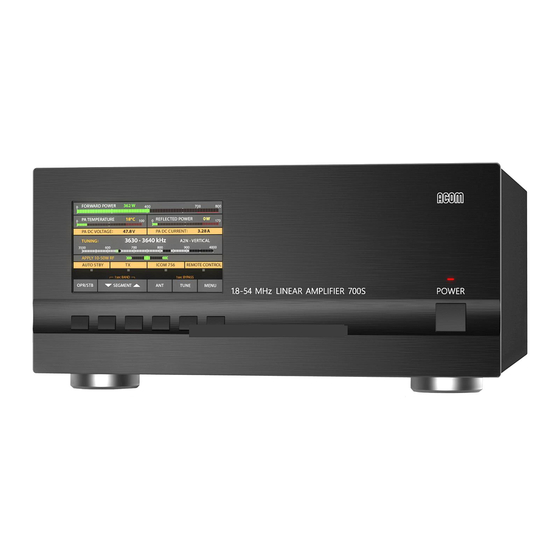
User's Manual | ACOM 700S | 1.8-54 MHz Linear Amplifier Figure 3-1 Front panel - Controls and Readouts Initial Turning On 3.3. In order to start up the amplifier, push and hold the front panel POWER button for one or two seconds. -
Page 22: Figure 3-2 Basic Screen
User's Manual | ACOM 700S | 1.8-54 MHz Linear Amplifier Figure 3-2 Basic screen The WARNING messages appear only temporarily (for about three seconds), afterwards the indication of the operating values is restored automatically (see Section 4.4.a) The first protection level - WARNING... -
Page 23: Control System - Buttons And Menus
User's Manual | ACOM 700S | 1.8-54 MHz Linear Amplifier CAT interface information When CAT is deactivated, this field is shaded. REMOTE CONTROL information field - flashing represents RS-232 port dataflow. Control System - Buttons and Menus 3.5. 1) The OPR/STB and the BAND buttons are used for manual (local) control (see... - Page 24 User's Manual | ACOM 700S | 1.8-54 MHz Linear Amplifier Now in Receive mode select a frequency which is not occupied at the moment and press shortly the PTT or TX key while watching the output power and the SWR readings. If the power or SWR at the transceiver output are too high (over 5 W or SWR over 2:1) release the key and check for the reason as follows: Check again whether the power control is set at minimum;...
- Page 25 User's Manual | ACOM 700S | 1.8-54 MHz Linear Amplifier RX mode must change to TX; • The reflected power must read below 20 W; • The forward power must read between 20 and 150 W with minimum drive power from the •...
- Page 26 User's Manual | ACOM 700S | 1.8-54 MHz Linear Amplifier Place as far away as possible (also by height) the radiating elements of antennas from the • premises, where the affected devices are located; in this sense, asymmetrical antennas without a separate feeder (Long Wire, Windom, and similar) may cause more interference because their radiating element begins immediately from the shack (part of it is the feeder itself);...
-
Page 27: Operation
User's Manual | ACOM 700S | 1.8-54 MHz Linear Amplifier 4. OPERATION Change of Modes RX/TX and Operate/Stand-by; AUTO OPERATE user setting 4.1. Stand-by mode In Stand-by mode, as well as when the amplifier is not powered, receiving and transmitting (no more than 200 W) with the transceiver is done via RF bypass between RF INPUT and RF OUTPUT of the amplifier. -
Page 28: Band Change, Standard And Expanded Frequency Coverage
User's Manual | ACOM 700S | 1.8-54 MHz Linear Amplifier AUTO OPERATE user setting AUTO OPERATE user setting can be turned on/off by the operator in the USER PREFERENCES menu (see Section ) or by a remote control 5.4 Menu USER PREFERENCES Figure 5-5 Menu USER PREFERENCES command. -
Page 29: Operation With An External Antenna Tuner
The ACOM 04AT can be installed both in the shack and in a remote location (even out in the open, close to the antennas). It can be distanced up to 100 m (330 ft) from the amplifier, using a single coaxial cable. -
Page 30: Automatic Protection System
User's Manual | ACOM 700S | 1.8-54 MHz Linear Amplifier Automatic Protection System 4.4. The ACOM 700S control unit (see Section ) keeps track of 7.4 Using the Fault Codes (signatures) for Diagnostics most amplifier analogue and logic signals in all modes. Those are the receive/transmit control signal, the... - Page 31 User's Manual | ACOM 700S | 1.8-54 MHz Linear Amplifier The second protection level - SOFT FAULT The second protection level is a SOFT FAULT - when a value exceeded the safe level, but does not put the amplifier in a danger of a failure.
-
Page 32: Menus - Settings And Options
User's Manual | ACOM 700S | 1.8-54 MHz Linear Amplifier 5. MENUS - SETTINGS AND OPTIONS By pushing the MENU button (the rightmost on ) the user invokes the MENU Figure 3-2 Basic screen SELECTION screen (see ). Each menu can be selected by the ITEM (up and down) Figure 5-1 MENU SELECTION buttons and SELECT. -
Page 33: Menu Amp Measure (Amplifier Measurements)
User's Manual | ACOM 700S | 1.8-54 MHz Linear Amplifier Menu AMP MEASURE (Amplifier measurements) 5.1. The menu AMP MEASURE (see ) is accessible from the MENU SELECTION Figure 5-2 Menu AMP MEASURE screen (see ) in all modes. Here you can constantly observe the values of eleven Figure 5-1 MENU SELECTION parameters. -
Page 34: Menu Amp Service (Amplifier Service Functions)
User's Manual | ACOM 700S | 1.8-54 MHz Linear Amplifier Menu AMP SERVICE (Amplifier Service Functions) 5.2. The amplifier service menu (see ) is accessible from the MENU SELECTION Figure 5-3 Menu AMP SERVICE screen (see ) at RX mode only. -
Page 35: Menu Cat/Aux Settings (Selection Of Cat/Aux Interface)
User's Manual | ACOM 700S | 1.8-54 MHz Linear Amplifier Menu CAT/AUX SETTINGS (Selection of CAT/AUX interface) 5.3. After a CAT cable is connected to both the transceiver and amplifier, the correct settings for the transceiver have to be entered via this menu. If there is no CAT connection, OFF has to be selected as Interface type. - Page 36 User's Manual | ACOM 700S | 1.8-54 MHz Linear Amplifier Tranceiver Interface Comm set ELECRAFT RS-232 ICOM (Connection to the REMOTE jack) ICOM (Connection to the RS-232 port or CT17) RS-232 KENWOOD TS-2000, 480, 590, 890, 990 and similar RS-232...
-
Page 37: Menu User Preferences
Menu USER PREFERENCES 5.4. Figure 5-5 Menu USER PREFERENCES ANTENNA TUNER/SWITCH INSTALLED If ACOM 04AT remote automatic antenna tuner is installed, select YES. Refer to ACOM 04AT User's Manual (available for download at www.acom-bg.com AUTOMATIC MENU EXIT When AUTOMATIC MENU EXIT is turned on, the amplifier exits the currently selected menu if no button has been pressed for more than 5 minutes. -
Page 38: Menu Faults Log
User's Manual | ACOM 700S | 1.8-54 MHz Linear Amplifier OPERATE ACCESS When locked, the amplifier remains in Standby and cannot be switched to Operate unless unlocked in the same menu. Passwords are not used – this is only a simple protection against possible child actions, or involuntary switching to Operate mode. -
Page 39: Menu Restore Default Settings
User's Manual | ACOM 700S | 1.8-54 MHz Linear Amplifier Menu RESTORE DEFAULT SETTINGS 5.6. Four different factory-reset levels are available (see Figure 5-7 Menu RESTORE DEFAULT SETTINGS In order to confirm the selected action, the operator must push the ACTION - left (YES) button once more. -
Page 40: Remote Control
Remote Control via ACOM eBox 6.1. Remote control of ACOM 700S via Internet is provided by the ACOM eBox Ethernet Remote Control device. The operation of ACOM 700S with ACOM eBox is described in the ACOM eBox User's Manual (available for download at www.acom-bg.com Use of other remote control devices is not recommended. -
Page 41: Maintenance
7. MAINTENANCE DANGER Both the mains voltage and the high DC voltage up to 500 V inside the ACOM 700S amplifier are LETHAL! For your safety, pull the amplifier power plug out of the mains wall outlet and WAIT AT LEAST 3 minutes EACH TIME BEFORE you remove the cover of the amplifier. -
Page 42: Cleaning
User's Manual | ACOM 700S | 1.8-54 MHz Linear Amplifier Cleaning 7.2. CAUTION Do not use any solvents for cleaning. They may be dangerous to you and damage amplifier surfaces, paint and plastic components. Do not open the amplifier. Cleaning of the amplifier outer surfaces can be done with a piece of soft cotton cloth lightly moistened with clean water. - Page 43 User's Manual | ACOM 700S | 1.8-54 MHz Linear Amplifier Suitable 16 A fuses are: Littelfuse, PN: 0216016.MXP (ceramic body cartridge); • This fuse can be ordered from: - Farnell (www.farnell.com), PN: 1354551; - Mouser (www.mouser.com), PN: 576-0216016. ESKA, PN: 520.030 (glass body cartridge);...
-
Page 44: Using The Fault Codes (Signatures) For Diagnostics
The data can be read in a plain-text format with a computer, using a standard terminal program. You can send the recorded file to your dealer or to ACOM accordingly. They could also provide the necessary instructions, if you choose to decode the downloaded hexadecimal data by yourself. -
Page 45: Firmware Updates
FAULTS LOG before you undertake any action. When ACOM issues a new firmware version, the user can upload it in the amplifier after he checks the compatibility. When compatibility is confirmed a return to an earlier version is also possible. -
Page 46: Specifications
User's Manual | ACOM 700S | 1.8-54 MHz Linear Amplifier 8. SPECIFICATIONS Parameters 8.1. Standard Frequency Coverage* 1.800 - 2.000 MHz (160 m band) 3.500 - 4.000 MHz (80 m band) 5.250 - 5.450 MHz (60 m band)** 7.000 - 7.300 MHz (40 m band) 10.100 - 10.150 MHz... -
Page 47: Functions
Frequency control directly by CAT from the transceiver Remote control through ACOM eBox Ethernet Remote Control device or via RS-232 interface Remote POWER ON by DSR/DTR and CTS/RTS lines on the RS-232 port or by ACOM eBox Ethernet Remote Control device Remote POWER ON / TURN OFF by DC voltage impulse or continuous DC voltage on CAT/AUX port ON_RMT input. -
Page 48: Storage And Shipment
User's Manual | ACOM 700S | 1.8-54 MHz Linear Amplifier Storage and Shipment 8.3. 8.3.1. Storage Environment The amplifier may be kept packed in a dry, ventilated and unheated location (with no chemically active substances such as acids or alkalis) within the following environment ranges:... -
Page 49: Information On Disposing And Recycling Of Old Electrical And Electronic Equipment
User's Manual | ACOM 700S | 1.8-54 MHz Linear Amplifier Information on Disposing and Recycling of Old Electrical and Electronic Equipment 8.4. The information in this section is applicable for countries that have adopted separate waste collection systems. ACOM products cannot be disposed as household waste. -
Page 50: Notes
User's Manual | ACOM 700S | 1.8-54 MHz Linear Amplifier NOTES ……………………………………………………………………………………………………………..…………………………………………………………………………………………………………………….. ……………………………………………………………………………………………………………..…………………………………………………………………………………………………………………….. ……………………………………………………………………………………………………………..…………………………………………………………………………………………………………………….. ……………………………………………………………………………………………………………..…………………………………………………………………………………………………………………….. ……………………………………………………………………………………………………………..…………………………………………………………………………………………………………………….. ……………………………………………………………………………………………………………..…………………………………………………………………………………………………………………….. ……………………………………………………………………………………………………………..…………………………………………………………………………………………………………………….. ……………………………………………………………………………………………………………..…………………………………………………………………………………………………………………….. ……………………………………………………………………………………………………………..…………………………………………………………………………………………………………………….. ……………………………………………………………………………………………………………..…………………………………………………………………………………………………………………….. ……………………………………………………………………………………………………………..…………………………………………………………………………………………………………………….. ……………………………………………………………………………………………………………..…………………………………………………………………………………………………………………….. ……………………………………………………………………………………………………………..…………………………………………………………………………………………………………………….. ……………………………………………………………………………………………………………..…………………………………………………………………………………………………………………….. ……………………………………………………………………………………………………………..…………………………………………………………………………………………………………………….. ……………………………………………………………………………………………………………..…………………………………………………………………………………………………………………….. ……………………………………………………………………………………………………………..…………………………………………………………………………………………………………………….. ……………………………………………………………………………………………………………..…………………………………………………………………………………………………………………….. ……………………………………………………………………………………………………………..…………………………………………………………………………………………………………………….. ……………………………………………………………………………………………………………..…………………………………………………………………………………………………………………….. ……………………………………………………………………………………………………………..…………………………………………………………………………………………………………………….. ……………………………………………………………………………………………………………..…………………………………………………………………………………………………………………….. Page 50 of 52 | S e c t i o n NOTES... - Page 51 User's Manual | ACOM 700S | 1.8-54 MHz Linear Amplifier This manual is for electronic distribution mainly. If you have it on paper and you no longer need it, please, recycle it! The latest versions of our User's Manuals are available at www.acom-bg.com...
- Page 52 о о support@acom-bg.com ACOM and the ACOM logo are registered trademarks of ACOM Ltd. in many countries, www.acom-bg.com including the EU and United States. I The used images are illustrative only. Subject to change without notice. I Printed in Bulgaria.
Need help?
Do you have a question about the 700S and is the answer not in the manual?
Questions and answers