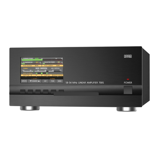
Acom 700S Operating Manual
Hf + 6 m linear amplifier
Hide thumbs
Also See for 700S:
- User manual (52 pages) ,
- Operating manual (30 pages) ,
- User manual (92 pages)
Advertisement
Advertisement
Table of Contents

Related Manuals for Acom 700S


Summary of Contents for Acom 700S
- Page 1 HF + 6 m LINEAR AMPLIFIER OPERATING MANUAL Outstanding HF Power Products...
-
Page 2: Table Of Contents
TABLE OF CONTENTS GENERAL INFORMATION .........................3 1-1. Inroduction and description .......................3 1-2. Owner assistance ........................3 1-3. Equipment supplied and options ....................3 1-4. Features ............................4 1-5. Safety considerations, explicit definitions .................4 INSTALLATION ............................5 2-1. Unpacking and Initial Inspection ....................5 2-2. Amplifier operating location selection; cooling................6 2-3. -
Page 4: General Information
If technical or operating assistance is needed, please contact your local dealer first. In the unlikely case of you needing further information, you may get in touch with ACOM via: fax (+ 359 2 920 96 56), telephone (+359 2 9209780), e-mail (acom@acom-bg.com, acom@mail.orbitel.bg) or by post (blvd. -
Page 5: Safety Considerations, Explicit Definitions
FCC regulations. This operating manual contains precautions, cautions, and warnings that MUST BE CОMPLIED TO by the user to ensure safe operation and maintaining of the ACOM 700S amplifier in a safe working condition. -
Page 6: Installation
W A R N I N G Do not undertake repairs or changes in hardware or firmware of your ACOM 700S amplifier. Doing so will endanger your or others‘ health or life, or damage the amplifier and the equipment connected to it. Such repairs or changes are not covered by the warranty and may void the warranty. -
Page 7: Amplifier Operating Location Selection; Cooling
Locate the amplifier close to the place where will be used. You will need an easy access to the rear panel for connecting cables, and of course, to the buttons and screen on the front panel. The ACOM 700S is forced air cooled. Locate the amplifier so that there are no objects or other devices closer than 10cm (4”). - Page 8 b) KEY-IN jack - amplifier input for receive/transmit control from the transceiver. The transceiver switches the amplifier from receive mode into transmit mode (RX/TX) by grounding of the KEY-IN input. Run a shielded cable from the output of your transceiver, providing “ground on transmit”, to the KEY-IN input on the amplifier rear panel (RCA PHONO jack –...
- Page 9 The transceiver manufacturers give different names to this input, for example: TX-INHIBIT, MUTE, LINEAR, and others. Check the manual of your transceiver. Approach your dealer for details. If your transceiver has no such input, do not worry – ACOM 700S will operate normally with KEY-OUT unconnected.
-
Page 10: Installing Options And Connecting To External Devices, Computer, Etc
2-1 below and the respective menu in S. 5-3, table 5-1 and Fig. 5-3). Most of the modern transceivers can be connected by CAT to the ACOM 700S. This will allow the amplifier to track the transceiver frequency without any transmission and change the bands automatically when in Operate mode. -
Page 11: Powering And Operation
Table 2-2 RS 232 PIN NAME DESCRIPTION SPECIFICATIONS interface Not connected Transmitted Data RS232 level output Received Data RS232 level input Not connected Ground 0 Volt Remote Power On RS232 level input Not connected Remote Power On RS232 level input Not connected Rear panel view...
Need help?
Do you have a question about the 700S and is the answer not in the manual?
Questions and answers