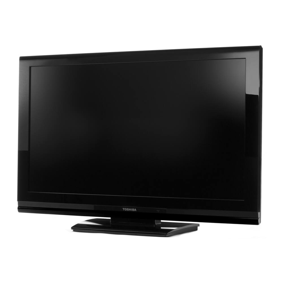
Toshiba 26AV502U Service Manual
Lcd color television
Hide thumbs
Also See for 26AV502U:
- Owner's manual (62 pages) ,
- Specifications (2 pages) ,
- Brochure (2 pages)
Advertisement
Quick Links
SERVICE MANUAL
For Technical Bulletins, Technical Tips, or other information regarding the
service of this model, visit the Toshiba America Consumer Products National
Service Division website at:
This model is classified as a
This Service Manual describes replacement parts for the green product. When repairing this
green product, use the part(s) described in this manual and
For (*1) and (*2), refer to
SOLDER.
© TOSHIBA CORPORATION 2009
LCD Color Television
26AV502U
www7.toshiba.com
green product
(*1), as indicated by the underlined serial number.
GREEN PRODUCT PROCUREMENT
Rev.1
lead-free solder
(*2).
LEAD-FREE
and
Advertisement

Related Manuals for Toshiba 26AV502U


Summary of Contents for Toshiba 26AV502U
- Page 1 SERVICE MANUAL LCD Color Television 26AV502U Rev.1 For Technical Bulletins, Technical Tips, or other information regarding the service of this model, visit the Toshiba America Consumer Products National Service Division website at: www7.toshiba.com This model is classified as a green product (*1), as indicated by the underlined serial number.
- Page 2 EXPRESS OR IMPLIED WARRANTY OF MERCHANTABILITY AND FITNESS FOR A PARTICULAR PURPOSE. Toshiba shall not be liable for any damages, losses, expenses or costs, if any, incurred in connection with or as a result of use of any information or data provided herein.
- Page 3 that have these same characteristics. Use only the specified parts when the mark is indicated in the circuit diagram or parts list. Part mounting and wire routing should be the same as that used originally. For safety purposes, insulating materials such as isolation tubes or tape are sometimes used and printed circuit boards are sometimes mounted floating.
- Page 4 fluid should contact the skin or clothing, wipe off with alcohol, etc., and rinse thoroughly with water. If the fluid should enter the eyes, immediately rinse the eyes thoroughly with running water. When attaching the LCD module to the LCD cover, position it appropriately and fasten at the position where the display can be viewed most conveniently.
- Page 5 CMOS-LSI circuitry is used in the LCD module, so avoid damage due to static electricity. When handling the module, use a wrist ground or anchor ground. Do not expose the LCD module to direct sunlight or strong ultraviolet rays for extended periods. Do not store the LCD module below the temperature conditions described in the specifications.
-
Page 6: Inverter Pcb
Power PCB P801 P803 Inverter PCB Alt. LVDS (26 in) P802 LVDS CN13 (Not used in later production) CN11 CN10 Tuner Main PCB CN101 CN12 Lamp Out 32AV502U... -
Page 7: Power Supply
Inverter Power Supply In/Out 1. 24V< 1. Gnd 2. 24V< 2. Gnd 3. 24V< 3. 24V Aud< 4. 24V< 4. 24V Aud< 5. 24V< 5. Gnd Wiring 6. Gnd 6. Gnd 7. Gnd Interconnect 7. Gnd 8. Gnd 8. 12V< Power Supply 9. -
Page 8: Lcd Panel
26/32/37AV502U-26/37AV52U Wiring Interconnect LCD Panel Power Board P802 P802 P803 P801... - Page 9 Panel out R_out Main Board DDR2 512M Audio NT5TU32M16CG-25C TPA3121D2 L_out Flash RAM M25P32-VFM I2S out output DTV system IC IF P/N WT61P7 24LC02 ZR39770 Supra HD-770 S/PDIF Audio I2S input Audio I2S output Audio switch AK4682EQ Tuner_CVBS CVBS CVBS Y/C input HD SW TX /...
- Page 10 PRIMARY SECONDARY P801 P801 F101 F101 LF102 LF102 LF101 LF101 BD101 BD101 R116 R116 D201 D201 L201 L201 +24Vinv/3.5A +24V +24V R122 R122 D102 D102 R123 R123 VA101 VA101 R117 R117 T101 T101 Q101 Q101 R118 R118 C114 C114 TH101 TH101 D202 D202...
- Page 11 Dead Set No Sound/ No Picture 5 VDC present at pins 10, 11, and 12 of P802 on the power supply module when AC is applied? Does a 4.3 volt on off signal appear at pin Suspect a problem with 13 of P802 when the the standby 5 volt supply on/off button is...
- Page 12 *** Warranty Authorization required if CN5. If it is present suspect a power supply problem with the display control display is replaced in warranty – Go module. board (Tcon). If it is not present replace the main PCB. to www7.toshiba.com for instructions.
- Page 13 Is 5VDC Replace the present at pin 16 of Main module. P802 soon (.5 sec) after the unit is turned on? *** Warranty Authorization required if display is replaced in warranty – Go to www7.toshiba.com for instructions.
- Page 14 No Audio Using the remote or the manual keyboard, access the audio menu to assure the speakers are on and the input selection is a known good source. Will this restore audio? Problem solved. Does the power supply generate the audio supply voltages (24 VDC at pins 3 and 4 of P802) when the unit is...
- Page 15 Firmware updating for this chassis family is accomplished via a USB port located on the rear of the unit. It is designated as “Service” and is located between the HDMI and PC audio input jacks. Visit the Toshiba website at www7.toshiba.com for the latest update information. Factory Mode...
- Page 16 Location Part No. Description E100 75013318 BEZEL ASSY, PC+ABS MBK99/MSV12, 26AV52U, 39C02251L16 E110 75012914 BACK COVER ASSY, TW2614 HI-PS MBK97, 26AV502U, 39C02251L10 E120 75012917 STAND ASSY, ABS 94HB MBK86/GLO, 39C02251L08 E200 75012905 PC BOARD ASSY, MAIN, 26AV502U, 39C02251L07 E250 75012912 POWER MODULE, (STW26T) FSP132-4F03 5/12/2, 39C02251L01...
- Page 17 TOSHIBA CORPORATION 1-1, SHIBAURA 1-CHOME, MINATO-KU, TOKYO 105-8001, JAPAN...