Advertisement
Available languages
Available languages
Quick Links
Advertisement
Chapters

Related Manuals for RTW SurroundControl 31900 Series


Summary of Contents for RTW SurroundControl 31900 Series
- Page 1 Manual SurroundControl 31900...
- Page 2 SurroundControl 31900...
- Page 3 Bedienungsanleitung SurroundControl 31900 Serie...
- Page 4 02/2012 | Technische Änderungen vorbehalten! Die PDF-Version auf dem Speichermedium enthält weiterfüh- RTW GmbH & Co. KG | Elbeallee 19 | 50765 Köln | Germany rende Informationen zu Funktionen und Einstellungen. Postfach 71 06 54 | 50746 Köln | Germany Fon +49 221.
-
Page 5: Allgemeine Sicherheitsanweisungen
Sicherheitshinweise Die folgenden Symbole sind auf dem Gehäuse des Gerätes, auf einzelnen Modulen und in dieser Bedienungsanleitung zu finden: WaRnung! allgemeine Sicherheitsanweisungen Dieses Symbol warnt Sie vor einer möglicherweise gefähr- lichen Situation, etwa vor gefährlichen Spannungen, die Sie • Vor Inbetriebnahme des Gerätes studieren Sie sorgfältig einem elektrischen Schock aussetzen könnten. -
Page 6: Warnung
• Entfernen Sie keine Teile aus dem Gerät und führen Sie aCHTung! keine Modifikation am Gerät aus ohne die schriftliche Freigabe durch RTW. Veränderungen am Gerät können sowohl Sicherheitsrisiken verursachen als auch die EMI- Folgen Sie immer den Sicherheitsmaßnahmen, um Verletzun- CE Konformität beeinflussen. gen oder Beschädigungen am Gerät oder anderen Objekten •... -
Page 7: Hinweis Zum Betrieb Mit Externen Schaltnetzteilen Der Schutzklasse Ii
Bei der Berührung von nicht- oder nicht korrekt angeschlosse- sprechend den anschlussbelegungen verkabelt werden! nen Geräten mit Stromversorgung durch externe Schaltnetztei- le der Schutzklasse II (wie. z. B. RTW 1168-R, im Lieferumfang Sind die Anschlusskabel korrekt aufgelegt, kann die angespro- der 31960 Serie) können empfindsamere Personen das chene Thematik nicht auftreten. -
Page 8: Umweltschutz
Umweltschutz • Batterie-Recycling Beachten Sie die folgenden Informationen zur Umweltver- träglichkeit des Gerätes und die Hinweise, wenn Sie ein Gerät Dieses Gerät kann wiederaufladbare Nickel-Cadmium- oder Bauteile recyceln möchten (Handhabung am Ende der (NiCd) oder Lithium-Ionen- (Li-Ion) Batterien enthalten, Produktlebensdauer): die auf geeignete Weise wiederverwertet oder entsorgt werden müssen. -
Page 9: Table Of Contents
Inhaltsverzeichnis Sicherheitshinweise 6.8 | Einstellungen im Menü ändern Allgemeine Sicherheitsanweisungen 6.9 | Presets speichern Warnung! 6.10 | Das Routing anpassen Achtung! 6.11 | Start-Preset definieren Hinweis zum Betrieb mit externen Schaltnetzteilen der 6.12 | Skalen und Pegelreferenzen verändern Schutzklasse II 6.13 | Loudness-Anzeigeoptionen verwenden umweltschutz 7 | Steuerung... - Page 10 8.4 | Das VSC-Instrument 8.13 | Das DOLBY® META DATA-Instrument 101 8.4.1 | Änderungen der Parameter für das VSC-Instru- 8.13.1 | Aktivierung des Decoders und Ändern der Para- ment meter 8.4.2 | Die Funktionen des VSC-Instruments 8.13.2 | Die Funktionen des DOLBY® META DATA-Instru- Vektorskop-Funktionen im Surround-Modus ments Vektorskop-Funktionen im Multi-Channel-Modus 8.14 | Das DIALNORM-Instrument Vektorskop-Funktionen im 2-Channel Stereo-Mo- 8.14.1 | Hintergrund –...
- Page 11 12 | abmessungen 9.4.2.7 | Downmix and Peakmeter Settings für den Downmix Routing-Bereich 13 | Technische daten 9.4.2.8 | Die Peakmeter-Parameter in den Channel Groups (PPM-Modus) 14 | Preset-liste 9.4.2.9 | PPM + Loudness Settings für den Monitoring Routing-Bereich 14.1 | Allgemein 9.4.2.10 | Die Parameter der Channel Group (Loud- 14.2 | Peakmeter-Einstellungen ness-Modi)
- Page 12 DE-10 Inhaltsverzeichnis SurroundControl 31900/31960 Serie...
-
Page 13: Bevor Sie Beginnen
1 | Bevor Sie beginnen Vielen Dank für den Erwerb eines Modells der Surround- wie Surround, Stereo und Mehrkanal in den verschiedensten Control Serien, den achtkanaligen analogen und digitalen professionellen Audio-Anwendungen wie Broadcast, Pre- und Monitoring-Controllern mit Pegelmess- und Signalanalyse- Post-Produktionsumgebungen, Musik-Produktion, DVD- funktionen zur umfassenden messtechnischen und akusti- Mastering und Kino-Surround-Sound. -
Page 14: Zu Dieser Anleitung
1.2 | zu dieser anleitung Die Bedienungsanleitung ist so aufgebaut, dass Sie Schritt für Gehen Sie wie folgt vor: Schritt zu einer zügigen Inbetriebnahme geführt werden. Die • Lesen und verstehen Sie zuerst die Anleitung. Anleitung liegt in zwei Versionen vor: • Packen Sie das Gerät aus und prüfen Sie anhand der • Die gedruckte Version (Schnellstart-Kurzanleitung) enthält Liste, ob Sie alle Ihrem Gerät entsprechenden Kompo- die wichtigsten Informationen, um das Gerät in Betrieb nenten erhalten haben. -
Page 15: Lieferumfang
2 | Lieferumfang Packen Sie das Instrument aus, finden Sie unten Ihre Version und prüfen Sie, ob Sie alle entsprechenden Komponenten erhal- ten haben. Falls Teile fehlen, wenden Sie sich bitte an Ihren Händler. Passendes Zubehör finden Sie im nächsten Abschnitt. SurroundControl 31900 Serie >... -
Page 16: Zubehör
3 | Zubehör 8-fach Adapterkabel, 4 m 8-fach Adapterkabel, 4 m 8-fach Adapterkabel, 4 m 1186 1163 1167 • von 25-pol. Sub-D-Anschluss auf • von 25-pol. Sub-D-Anschluss auf • von 25-pol. Sub-D-Anschluss auf 8 XLR-F-Kupplungen 8 XLR-M-Kupplungen 4 XLR-F- und 4 XLR-M-Kupplungen • für Anschlüsse „Meter In analog“ • für Anschluss „Analog Out“ • für Anschlüsse „Digital In/Out“ und „Analog In“ SurroundControl 31900 Serie 19“/1He-Basiseinheit incl. -
Page 17: Anschlüsse
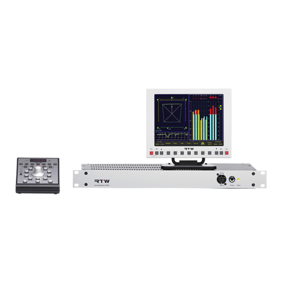
Zusätzlicher Schutz- Schutz- erdung leiteran- schluss Optional: USB-A- oder Maus Mess-Mikrofon 13720: RTw Remote Display RTw Remote Control Optional: 30010: 30050: optionales RTW-Zubehör (XLR-F-An- Standard-VGA-Monitor schluss auf der Gehäuse-Front-Seite) optionales RTW-Zubehör im Lieferumfang © 09/2011 | Technische Änderungen vorbehalten. SurroundControl 31900 4 | Anschlüsse | 4.1 | Anschlussverbindungen... -
Page 18: Pin-Belegung
Ausgang Analog 3 (–, kalt) Schirm/Gehäuse HInweIs - Die Länge des VGA-Kabels beträgt max. 10 Ausgang Analog 2 (+, heiß) bis 15 m! Beim Anschluss des RTW Remote Display 30010 müssen alle Adern im Verbindungskabel belegt sein! Ausgang Analog 2 (–, kalt) Schirm/Gehäuse Ausgang Analog 1 (+, heiß) - Page 19 Pin-Belegung (Fortsetzung) „Digital 3 In/Out“, „Digital 4 In/Out“ (25-pol. Sub-D-F) „Ref sync In“ (25-pol. Sub-D-F) Pin: Funktion: Pin: Funktion: Audio-Ausgang digital 4 (+, heiß) für zukünftige Nutzung � � � � � � � � � � � � � � � � �...
-
Page 20: Inbetriebnahme
Remote Display 30010 darauf, dass alle Adern belegt sind. Kabel angeschlossen werden. Zur Anzeige wird ein externer VGA-Monitor benötigt, optional bietet RTW das in Design und Für die Verbindung mit den übrigen Schnittstellen werden han- Farbgebung passende 8,4” Remote Display 30010 an. Alle delsübliche Verbindungskabel benötigt. -
Page 21: Erste Schritte
31900 Serie, Option für die 31960 Serie) • Analoge bzw. digitale Audio-Eingangssignale nahme des Geräts oder nach einem Software-Update dauert • Analoge bzw. digitale Lautsprecher-Verbindungen möglicherweise deutlich länger. • Externer VGA-Bildschirm, z. B. RTW Remote Display 30010 (für die 31900 Serie erforderlich) • optionale USB-Maus • LAN/Ethernet-Netzwerkanschluss (falls benötigt) • Netzspannung Wir nehmen an, dass Sie Ihren SurroundControl zum ersten Ausführliche Informationen zu den Parametern und einige... -
Page 22: Synchronisationsquelle Und Abtastrate Einstellen
6.2 | Synchronisationsquelle und Abtastrate einstellen Die vom Gerät verwendete Synchronisationsquelle und -art sowie die interne Abtastrate sind globale Parameter, die durch das Laden neuer Presets oder Sub-Presets nicht verändert werden. Cursor-Tasten Funktions-Tasten zum Speichern oder Verwerfen der Einstellungen Cursor-Tasten Gehen Sie wie folgt vor, um diese Einstellungen Ihrer Studio-Umgebung anzupassen: Drücken Sie im Normalbetrieb die Taste Menu. Beim Speichern Sie Ihre Einstellungen, indem Sie auf die Taste Save &... -
Page 23: Presets Verwenden
6.3 | Presets verwenden Zu den ersten Schritten bei der Konfiguration Ihres Systems Durch Laden eines Factory-Presets können Sie die Kanalkon- wird das Auswählen des richtigen Presets und den darin ent- figuration definieren, mit der Sie arbeiten möchten. So wird beispielsweise F8 für Surround-Setups im 5.1-Format verwen- haltenen lokalen Einstellungen für Ihr Einsatzgebiet und die det, während F9 für Zweikanal-Stereosignale und F10 für den... -
Page 24: Factory-Presets Laden
6.4 | Factory-Presets laden Schaltflächen Namen der Factory-Presets Steuerleiste Nummern der MOde u. MORe zeigen die Kanal-Konfiguration (Fenster 1) Factory-Presets Gehen Sie wie folgt vor, um ein Preset zu laden: Drücken Sie die Taste MOde, bis die Schaltfläche MORe Laden Sie das gewünschte Factory-Preset, indem Sie eine der Tasten 1 bis 7 drücken. Das neue Preset wird in der Steuerleiste gelb wird. -
Page 25: Eingangsquellen Mit Sub-Presets Umschalten
6.5 | Eingangsquellen mit Sub-Presets umschalten Schaltfläche Verwendete Eingangs- Steuerleiste Namen der input Anschlüsse (Fenster 1) Sub-Presets Gehen Sie wie folgt vor, um zwischen den (bis zu) 7 Sub-Presets eines Factory- oder User-Presets umzuschalten: Drücken Sie die Taste input. Die entsprechende Schalt- Laden Sie das gewünschte Sub-Preset, indem Sie eine fläche befindet sich in der Steuerleiste oberhalb der der Tasten 1 bis 7 drücken. Das neue Sub-Preset wird Schaltflächen MOde und MORe und ist immer mit dem verzögerungsfrei geladen. -
Page 26: Instrument In Fenster 3 Auswählen
6.6 | instrument in Fenster 3 auswählen (RTa). Die Instrumente können im instrument Select-Modus Das Fenster 3 (der obere linke Bereich des Bildschirms) kann viele verschiedene Instrumente (Darstellungsarten) anzeigen, sehr einfach ohne das Laden neuer Presets oder den Zugriff darunter den Surround-Sound-Analyzer (SSa), das Vektorskop auf das Menüsystem gewechselt werden. -
Page 27: Abhörlautsprecher Steuern
6.7 | abhörlautsprecher steuern Neben der Steuerung der Anzeigefunktionen ist die Remote vor allem ein vollständig ausgestatteter Surround-Abhör- Control 30050 für die 31900 Serie (entsprechend das rechts Controller mit numerischer Anzeige der eingestellten Abhör- neben dem Display angeordnete Bedienfeld der 31960 Serie) lautstärke. -
Page 28: Einstellen Des Abhör-Bezugspegels
6.7.3 | einstellen des Abhör-Bezugspegels 6.7.4 | Abhören einzelner Kanäle (solo) Gehen Sie wie folgt vor, um einen einzelnen Kanal abzu- In allen Kanal-Konfigurationen mit Ausnahme von 6.1 spei- chert das Drücken der Taste CS (unterhalb des Volume- hören: Drehgebers) den aktuell eingestellten Abhörpegel als Abhör-Bezugspegel. Drücken Sie auf der Remote Control 30050 die kleine schwarze Taste Select, bis die LED Solo aufleuchtet. -
Page 29: Stummschalten Einzelner Kanäle (Cut)
6.7.5 | stummschalten einzelner Kanäle (Cut) 6.7.7 | nach-vorne-schalten der surround-Kanäle Gehen Sie wie folgt vor, um einen einzelnen Kanal Manchmal kann es für die Beurteilung der Surround-Kanäle ei- stummzuschalten: nes 5.1-Programms hilfreich sein, diese über die Front- anstatt über die Rück-Lautsprecher abzuhören. Die Funktion Swap Drücken Sie auf der Remote Control 30050 die kleine bietet eine einfache Möglichkeit, bestimmte Kanäle temporär schwarze Taste Select, bis die LED Cut aufleuchtet. -
Page 30: Einstellungen Im Menü Ändern
6.8 | einstellungen im Menü ändern Das Menüsystem ermöglicht sowohl den Zugriff auf alle lokalen Parameter, die in Presets gespeichert werden, als auch auf alle globalen (allgemeinen) Parameter, die beim Laden eines Presets unverändert bleiben. Menü-Karteikarte mit lokalen Parametern Menü-Karteikarten mit globalen Parametern Cursor-Tasten Funktions-Tasten zum Speichern oder Verwerfen der Einstellungen Cursor-Tasten... -
Page 31: Presets Speichern
Gehen Sie wie folgt vor, um lokale Parameter im Menü-system zu ändern: Drücken Sie im Normalbetrieb die Taste Menu. Beim Verwenden Sie die Schaltfläche edit selected preset, um ersten Zugriff auf das Menüsystem nach dem Systemstart die Untermenüs zur Anpassung der lokalen Einstellungen wird dieses initialisiert, daher dauert der Ladevorgang zu öffnen. einige Sekunden. -
Page 32: Das Routing Anpassen
6.10 | das Routing anpassen Falls die Routing-Einstellungen des ausgewählten Sub-Presets nicht mit dem in Ihrer Installation verwendeten Anschluss-Sche- ma übereinstimmen, können Sie das Routing des Sub-Presets im Menüsystem nach Wunsch verändern. Das neue Routing kann in einem der User-Presets U1 bis U 7 gespeichert werden. Gehen Sie wie folgt vor, um das Eingangs-Routing zu ändern: Drücken Sie im Normalbetrieb die Taste Menu. - Page 33 Verwenden Sie das Kombinationsfeld Source, um die 13. Verwenden Sie nach Abschluss Ihrer Einstellungen die Schaltfläche Close der oder des geöffneten Menüfenster (s), gewünschte Eingangsbuchse des Geräts einzustellen. bis der Save Preset-Dialog angezeigt wird. Verwenden Sie die darunter liegenden Kombinationsfel- der (die z.
-
Page 34: Start-Preset Definieren
6.11 | Start-Preset definieren Die SurroundControl-Geräte können so konfiguriert werden, dass sie nach dem Einschalten entweder ein vordefi niertes Preset oder das vor dem Abschalten zuletzt verwendete Preset laden. Gehen Sie wie folgt vor: Drücken Sie im Normalbetrieb die Taste Menu. Beim Zum Speichern der veränderten Einstellungen und zum Verlassen des Menü-Systems drücken Sie die Taste Save ersten Zugriff auf das Menüsystem nach dem Systemstart &... -
Page 35: Skalen Und Pegelreferenzen Verändern
6.12 | Skalen und Pegelreferenzen verändern Die SurroundControl-Geräte unterstützen zahlreiche unterschiedliche Pegelreferenzen. Gehen Sie zum Verändern dieser globalen Parameter wie folgt vor: Drücken Sie im Normalbetrieb die Taste Menu. Beim Zum Speichern der veränderten Einstellungen und zum Verlassen des Menü-Systems drücken Sie die Taste Save ersten Zugriff auf das Menüsystem nach dem Systemstart & exit. Der Bildschirm zeigt das Bestätigungsfenster wird dieses initialisiert, daher dauert der Ladevorgang Save global Settings? an. -
Page 36: Loudness-Anzeigeoptionen Verwenden
6.13 | loudness-anzeigeoptionen verwenden Die SurroundControl-Geräte unterstützen verschiedene Loudness-Modi entsprechend der aktuellen Standards für die Darstel- lung von Lautheitsinformationen auf den Bargraph-Instrumenten im Program Meter. HinWeiS - Die Loudness-Anzeigeoptionen stehen nur für digitale Signale in den Kanal-Konfigurationen 2-Kanal- Stereo und 5.1-Surround zur Verfügung. Gehen Sie wie folgt vor, um einer der Loudness-Anzeigeoptionen für das Program Meter zu konfigurieren: Drücken Sie im Normalbetrieb die Taste Menu. - Page 37 Verwenden Sie die Cursor-Tasten Ù und Ú, um auf die 12. Verwenden Sie die Schaltfläche Change name, um den Schaltfläche Monitoring input Routing zu gelangen, Namen des Presets zu ändern. Eine Menü-Seite mit Tasta- und die rote Taste Sel, um die Untermenüs zu öffnen. Es turfeldern erscheint.
- Page 38 DE-36 6 | Erste Schritte | 6.13 | Loudness-Anzeigeoptionen verwenden SurroundControl 31900/31960 Serie...
-
Page 39: Steuerung
7 | Steuerung Die SurroundControl Einheiten bieten umfangreiche Abhör- und Anzeigefunktionen zur vielfältigen Analyse von Surround-, Mehrkanal- oder Stereo-Audio-Signalen. Diese werden nachfolgend Instrumente genannt. Zur Anzeige der Instrumente ist das Display in bis zu vier Fens- können größere Instrumente Fenster überdecken. Die Größe ter unterteilt und kann gleichzeitig bis zu drei Instrumente und und Position der Fenster ist werksseitig festgelegt und kann die Steuerleiste mit den verschiedenen Steuertasten darstellen. -
Page 40: Allgemeines
7.1 | allgemeines Die Anzeigefunktionen (Instrumente) und das Menü der SurroundControl-Geräte können grundsätzlich auf drei verschiedenen Wegen gesteuert werden: Über die Bedienelemente, mit einer Maus über die Steuerleiste (Fenster 1) der grafi schen Bildschirm- Oberfl äche oder über die Steuertasten des als Option lieferbaren Remote-Displays 30010. SurroundControl 31960 VGA-Monitor zur Anzeige, z. B. -
Page 41: Mit Den Bedienelementen Steuern
Neben der Steuerung der Anzeigefunktionen stellen die Fern- Die SurroundControl-Geräte lassen sich auch extern über die bedien-Einheit Remote Control 30050 (31900 Serie) und die GP IO-Schnittstelle bedienen. Dabei können durch Steuersig- Bedienfelder auf der Frontseite der 31960 Serie vollständig nale die Anzeige- und Abhörfunktionen bedient und definierte ausgestattete Abhör-Controller dar. -
Page 42: Display Zur Anzeige Des Abhörschallpegels (Spl)
7.2.1 | Display zur Anzeige des Abhörschallpegels (sPL) Betätigen Sie die Taste 6 mit der Bezeichnung listening Die Abhörlautstärke kann im dreistelligen numerischen Display level, bis die gewünschte Option abs (absolut) oder rel und in der Sta tus-Box in Fenster 4 auf zwei unterschiedliche Arten angezeigt werden: (relativ) markiert ist. - Page 43 7.2.2 | Funktionstasten zur Bedienung der Instrumentenfunktionen Die Remote Control 30050 (31900 Serie), die Bedienfelder Die Belegung der Funktionstasten 1 bis 7 hängt vom ausge- auf der Vorderseite der 31960 Serie, sowie das Remote-Dis- wählten Instrument und vom Betriebszustand ab. Die gerade play 30010 besitzen insgesamt 7 Funktionstasten zur Auswahl aktiven Funktionen werden immer in der Steuerleiste ange- zeigt.
- Page 44 7.2.4 | Funktionsauswahl für die Kanaltasten Mit der kleinen schwarzen Select -Taste (ganz links auf der Diese Funktionen gelten für die Tasten, denen je nach Sur- Remote Control 30050, rechts etwa in der Mitte auf dem Be- round-Format die entsprechenden Kanäle zugeordnet werden. dienfeld der 31960 Serie) werden die Kanal-Funktionen ge- wählt;...
- Page 45 7.2.5 | lautsprecher-Kanaltasten schwarzen Select-Taste eingestellt. Einige dieser Tasten Mit den Kanaltasten werden die Kanalfunktionen der Laut- sprecherausgänge gesteuert. Die mit jeder Taste schaltba- haben je nach Surround-Format auch andere Funktionen. re Funktion (Solo, Cut, Swap, Phase) wird mit der kleinen 7.2.6 | 2C-Taste Diese Taste kann je nach Modus verschiedene Funktionen übernehmen: •...
- Page 46 7.2.7 | eX-Taste Diese Taste kann je nach Modus verschiedene Funktionen übernehmen: • 3.1-/5.1-/6.1-Modus • 7.1-Modus In diesem Modus wird der eX-Taste der rechte Cen ter- Unabhängig von der Funktionsauswahl der Kanalta s- ten über die kleine schwarze Select-Taste werden mit Kanal (RC) zugeordnet.
- Page 47 7.2.10 | Mono-Taste Diese Taste schaltet das Mono-Signal auf den Kanal (die (7) gedrückt wird. So kann die Wirkung unterschiedlicher Ein- Kanäle), der (die) in der Funktion Mono Mode im Monitoring- stellungen verglichen werden. Fenster 4 (Status-Box) zeigt bei Instrument ausgewählt wurde(n). Die in der Steuerleiste ange- Betätigung zusätzlich die Meldung „Mono active“.
- Page 48 7.2.12 | input-Taste (eingangsumschalter) Mit dieser Taste wird über die Sub Presets die Anwahl eines entsprechenden Tasten oder Schaltflächen 1 bis 7 kann durch Eingangs für den Abhör-Controller ermöglicht. Durch Drücken Laden des Sub Presets mit der gewünschten Eingangskonfi- der Taste werden in der Steuerleiste (Fenster 1) die 7 Sub guration die Eingangsquelle umgeschaltet werden.
- Page 49 7.2.14 | Output-Taste (ausgangsumschaltung) Diese Taste schaltet die Abhörsignale zwischen zwei im Menü vordefinierbaren analogen oder digitalen Hardware-Ausgängen um. Falls Sie für den aktiven Status der Output-Taste die Option Die beiden Ausgangsbuchsen, die bei aktiver bzw. inaktiver Output-Taste angesprochen werden, sind im Bereich Output downmix Solo gewählt haben und die Taste aktivieren, wer- Key Mode auf der input/Output Routing-Menü-Karteikarte den die Signale lo/Ro an die dafür vorgesehenen Ausgänge...
- Page 50 Gehen Sie bitte wie folgt vor, um im Multi-Channel-Modus eine andere Abhörgruppe auszuwählen: Wir setzen an dieser Stelle voraus, dass Sie im Multi- Die grünen Lautsprechersymbole am oberen Ende der Bargraphen im Program Meter-Bereich in Fenster 2 Channel-Modus arbeiten und dass Sie die von Ihnen benötigten Kanalgruppen und Kanäle bereits auf der verändern ihre Position entsprechend der gewählten Menü-Seite Monitoring input Routing definiert haben.
-
Page 51: Extern Über Die Gp Io-Schnittstelle Steuern
7.3 | extern über die gP iO-Schnittstelle steuern Die SurroundControl-Geräte lassen sich über externe Tasten, Umschalter oder Steuersignale fernbedienen, die an die GP IO- Schnittstelle angeschlos sen werden. Die Pin-Belegungen finden Sie im Abschnitt anschlüsse. 7.3.1 | GP IO-eingänge Alle 16 GP IO-Eingänge haben den Status active low. Mit Ab Werk können alle Tasten und Schaltflächen der Steuerleis- den Optionen des Preset Recall Mode-Rahmens auf der Key te sowie der Re mote Control 30050 (31900 Serie) bzw. -
Page 52: Gp Io-Ausgänge
7.3.2 | GP IO-Ausgänge Die SurroundControl-Geräte können über die GP IO-Schnitt- im SurroundControl das Sub Preset mit den Einstellungen stelle Steuersignale zur Aktivierung von Alarm-Indikatoren für die Dolby®-Signalquelle aktivieren, werden gleichzei- oder zur Steuerung externer Geräte und Anwendungen ausge- tig entsprechende GP IO-Ausgänge geschaltet. Diese ben. - Page 53 13. Falls Sie den Ausgängen die Alarmfunktion zugewiesen 22. Verwenden Sie die Cursor-Tasten Ù und Ú, um den Fokus auf die Schalt fläche Monitoring input Routing zu setzen. haben, verwenden Sie die Cursor-Tasten < und >, um die Menü-Karteikarte alarm Configuration auszuwählen. Die Bestätigen Sie diese Wahl mit der roten Select-Taste.
- Page 54 DE-52 7 | Steuerung | 7.3 | Extern über die GP IO-Schnittstelle steuern SurroundControl 31900/31960 Serie...
-
Page 55: Instrumente (Anzeigearten)
8 | Instrumente (Anzeigearten) 8.1 | die Bedienung der instrumente Die Instrumente und ihre Funktionen können auf verschie- des Remote Display 30010 oder optional per Computer-Maus dene Arten bedient werden: mit den Funktionstasten auf der durch Klick auf die Schaltflächen in der Steuerleiste des Bild- Remote Control 30050 (31900 Serie) bzw. -
Page 56: Die Steuerleisten-Betriebsarten Function-Select Und Instrument-Select
8.1.2 | Die steuerleisten-Betriebsarten Function-select und Instrument-select Die Steuerleiste kennt zwei Betriebsarten, zwischen denen mit der Taste MOde umgeschaltet wird: • Function-Select: Bedienung der Instrumentenfunktionen • Instrument-Select: Auswahl eines Instruments oder Aufruf eines Presets Der Grundzustand ist Function-Select. • Function-Select • Instrument-Select Die Betriebsart Function-Select erlaubt die Bedienung Die verfügbaren Instrumente sind auf den Schaltflächen in des aktiven Instrumentes. -
Page 57: Das Program-Meter-Instrument
8.2 | das Program-Meter-instrument Das Program Meter wird immer in Fenster 2 angezeigt. Durch Instrument RTa 1/6, dieses überschreibt Fenster 2 und somit Betätigen der Taste inSTR wird der Fokus (heller Rahmen) das Program Meter). Erneutes Drücken der Taste inSTR legt auf dieses Fenster gelegt. -
Page 58: Das Multi-Norm-Peak-Program-Meter (Ppm)
8.2.1 | Das Multi-norm-Peak-Program-Meter (PPM) Die Peakmeterdarstellung wird aus bis zu vier Peakmeter- gepasst. Die Bargraphen jeder Peakmeter-Gruppe bieten eine Gruppen (Channel groups) gebildet. Jede Gruppe kann un- numerische Anzeige, einen Over-Indikator und als zuschaltbare terschiedliche Domänen, Standards oder Einstellungen haben. Spots einen Peak-Hold-Indikator und eine SPL- oder Loud- Im Menü... - Page 59 PPM im Multi Channel-Modus Peakmeter-Gruppen (Channel Groups): Kanalbezeichnung (Label, stellt sich je nach Surround- Gruppe 1 Gruppe 2 Gruppe 3 Gruppe 4 Format automatisch ein) (Digital) Over Indikator. Rot: • Digital: Bei Erreichen der eingestellten Clipgrenze • Analog: Bei Erreichen des Maximalpegels ent- sprechend Standard Orange: Anzeige L MPSL Numerische Anzeige des Peak-Hold-Wertes...
-
Page 60: Änderung Der Parameter Für Das Peak-Program-Meter
8.2.1.1 | Änderung der Parameter für das Peak-Program-Meter Viele Parameter der PPM-Bargraphen, der Peak-Hold-Funktion und der Loudness-Anzeigen können in den Channel group- Menüs, die über die verschiedenen Peakmeter Settings-Schaltflächen erreicht und geändert werden. Gehen Sie bitte wie folgt vor, um zu den Channel Group-Menüseiten zu gelangen und Parameter zu ändern: Wählen Sie Menu. Das Gerät schaltet in den Menü- Wählen Sie auf der Menüseite Peakmeter Settings eine Modus. -
Page 61: Die Funktionen Des Peak-Program-Meter
8.2.1.2 | die Funktionen des Peak-Program-Meter Die Funktionen des Program Meter-Instruments im PPM-Modus können durch Klicken der nummerierten Schaltflächen in der Steuerleiste oder durch Drücken der entsprechenden Taste ausgewählt werden. • Memory Bei digitalen Eingangssignalen entspricht der Referenz- (Schaltfläche/Taste 1) punkt der Skalen DIN+5, DIN+10, Nordic, British IIa, British IIb, Zoom20 und Zoom2 dem eingestellten Head- Mit dieser Funktionswahl wird je nach Voreinstellung die... -
Page 62: Das Ppm + Loudness Meter (Loudness-Modi Itu Bs.1771, Ebu R128, Atsc A/85, Arib Oder Custom)
8.2.2 | Das PPM + Loudness Meter (Loudness-Modi ITU Bs.1771, eBU R128, ATsC A/85, ARIB oder Custom) Abhängig vom gewählten Kanal-Modus erzeugen die Loudness-Modi ITU BS.1771, EBU R128, ATSC A/85, ARIB und Custom im Program Meter bis zu 10 Bargraphen in bis zu 3 Gruppen: Die Bargraphen der Channel group zeigen den momen- In der lRa group kann ein Instrument zur Messung der •... -
Page 63: Änderung Der Ppm- Und Loudness-Parameter In Einem Der Loudness-Modi
8.2.2.1 | Änderung der PPM- und loudness-Parameter in einem der loudness-Modi Viele Parameter der PPM- und Loudness-Bargraphen können in der Channel group, Sum group und lRa group des Menüs PPM + loudness Settings angezeigt und/oder editiert werden. HinWeiS - Nach dem Anwählen einer der Loudness-Standards sind die meisten Loudness-Parameter fest auf die Werte des jeweiligen Standars eingestellt. -
Page 64: Die Funktionen Des Loudness-Meters (Modi: Itu Bs.1771, Ebu R128, Atsc A/85, Arib Oder Custom)
8.2.2.2 | Die Funktionen des Loudness-Meters (Modi: ITU BS.1771, EBU R128, ATSC A/85, ARIB oder Custom) Die Funktionen des Program Meters in einem der Loudness-Modi können durch Klicken der nummerierten Schaltflächen in der Steuerleiste oder durch Drücken der entsprechenden Taste ausgewählt werden. • Memory • Info/Chart/Numeric (Schaltfläche/Taste 1) (Schaltfläche/Taste 6) Wiederholtes Drücken dieser Funktionswahl schaltet die Mit dieser Funktionswahl wird die numerische Anzeige des Langzeitspeichers für den maximalen Loudness- Anzeigeoptionen für die Status-Box in Fenster 4 um:... -
Page 65: Das Ssa-Instrument
8.3 | das SSa-instrument Das SSa-Instrument wird immer in Fenster 3 angezeigt. Um stellung von Phantomschallquellen (PSI - Phantom Source es auszuwählen legen Sie durch Betätigen der Taste inSTR Indicator) und/oder Korrelatoren, die Gesamt-Lautheit (TVI - To- den Fokus (heller Rahmen) auf dieses Fenster. Es werden die tal Volume Indication), dominante Schallereignisse (DMI), Pha- Funktionen für den Surround-Sound-Analyzer in der Steuer- senbeziehungen und vieles mehr. -
Page 66: Was Wird Im Ssa-Instrument Dargestellt
8.3.1 | was wird im ssA-Instrument dargestellt? Mit Hilfe des Surround-Sound-Analyzers können für Signale Aussteuerung aller Kanäle mit einem Rauschsignal ergibt sich im Surround-Format folgende Anzeigen dargestellt werden: ein Quadrat, dessen Fläche ein Maß für die Gesamtlautstärke ist. Die Verteilung auf die vier Quadranten zeigt entsprechend Balance zwischen den Front- und Surroundkanälen die Lautstärkeverteilung an. - Page 67 Beispiele für Darstellungen im Surround-Sound-Analyzer Inkohärentes Rauschen mit gleichen Pegeln Identisches Sinus-Signal mit gleichen Pegeln Wie links, jedoch ist die Phase des linken Ka- in den Kanälen L, R, LS und RS, ausgesteuert auf in den Kanälen L, R, LS, RS. Die Korrelation ist nals um 180°...
-
Page 68: Die Funktionen Des Ssa-Instruments
8.3.2 | Die Funktionen des ssA-Instruments Surround-Sound-Analyzer-Funktionen im Surround-Modus Stereo-Sound-Analyzer-Funktionen im 2-Kanal-Stereo-Modus • PSI • (Schaltfläche/Taste 1) (Schaltfläche/Taste 1) Die Funktionswahl PSi (Phantom Source Indicator) akti- Die Funktionswahl dMi (Dominance Indicator) aktiviert viert bzw. deaktiviert die Anzeige der Phantomschallquel- bzw. deaktiviert die Anzeige der Dominanz im Stereo- len-Indikatoren. -
Page 69: Das Vsc-Instrument
8.4 | Das VSC-Instrument Das VSC-Instrument (Audio-Vektorskop) wird immer in Fens- zwischen jeweils einem wählbaren Kanalpaar an. Dieser An- ter 3 angezeigt. Um es auszuwählen legen Sie durch Betätigen zeigemodus beinhaltet zusätzlich eine Korrelationsgradanzeige der Taste inSTR den Fokus (heller Rahmen) auf dieses Fens- für die beiden gewählten Kanäle. -
Page 70: Die Funktionen Des Vsc-Instruments
8.4.2 | Die Funktionen des VsC-Instruments In Abhängigkeit der gewählten Betriebsart werden die verschiedenen Funktionen auf verschiedenen Schaltflächen dargestellt. Vektorskop-Funktionen im Surround-Modus • Input Select • 6.1 Surround-Modus: (Schaltfläche/Taste 1) (1) L – R Diese Funktionswahl öffnet eine weitere Funktionsebene (2) LS – RS zur Auswahl der Kanalpaare als Eingang für das 2-Kanal- (3) L –... -
Page 71: Vektorskop-Funktionen Im Multi-Channel-Modus
• Mode 2Ch/4Ch • Corr (Schaltfläche/Taste 2) (Schaltfläche/Taste 4) Diese Funktionswahl wechselt die Darstellung des Vek- Diese Funktionswahl wechselt die Anzeigegeschwindig- torskops zwischen 2- und 4-Kanal-Anzeige (2Ch/4Ch). keit des Korrelators zwischen schnell (Fast) und langsam Im 4-Kanalbetrieb werden in der oberen Hälfte immer (Slow). -
Page 72: Vektorskop-Funktionen Im 2-Channel Stereo-Modus
Vektorskop-Funktionen im 2-Channel Stereo-Modus • Input Select • Corr (Schaltfläche/Taste 1) (Schaltfläche/Taste 3) Diese Funktionswahl öffnet eine weitere Funktionsebene Diese Funktionswahl wechselt die Anzeigegeschwindig- zur Auswahl des Kanalpaares als Eingang für das 2-Ka- keit des Korrelators zwischen schnell (Fast) und langsam nal-Audio-Vektorskop. (Slow). • Grid •... -
Page 73: Das Corr-Instrument
8.5 | das CORR-instrument Das CORR-Instrument wird immer in Fenster 3 angezeigt. Um es auszuwählen legen Sie durch Betätigen der Taste inSTR den Fokus (heller Rahmen) auf dieses Fenster. Es werden die Funktionen für den Korrelator in der Steuerleiste (Fenster 1) angezeigt. •... -
Page 74: Die Funktionen Des Corr-Instruments
8.5.1 | Die Funktionen des CORR-Instruments Funktionen sind nur im 5.1 Surround-, 6.1 Surround- und 7.1 Surround-Modus verfügbar. • • Normal/LFE (Schaltfläche/Taste 1) (Schaltfläche/Taste 2) Die Funktionswahl lPF (Low Pass Filter) aktiviert (on) Die Funktion normal/lFe schaltet den Correlator zwi- bzw. -
Page 75: Das Rta 1/3- Und Das Rta 1/6-Instrument
8.6 | das RTa 1/3- und das RTa 1/6-instrument Die RTa-Instrumente werden immer in Fenster 3 angezeigt. Um Wenn das RTa 1/3-Instrument aktiviert ist, wird die Status- sie auszuwählen legen Sie mit der Taste inSTR den Fokus (hel- Box (Fenster 4) überschrieben. Der aktivierte RTa 1/6 ist das ler Rahmen) auf dieses Fenster. -
Page 76: Die Funktionen Der Rta-Instrumente
8.6.2 | Die Funktionen der RTA-Instrumente Die Steuerelemente des RTa 1/3 und des RTa 1/6 sind gleich, wenn sie jeweils im instrument Select-Modus der Steuerleiste ausgewählt wurden. RTa-Funktionen in den Surround-Modi 1. Funktionsebene Mit MORe-Taste 2. Funktionsebene DE-74 8 | Instrumente (Anzeigearten) | 8.6 | Das RTA 1/3- und das RTA 1/6-Instrument SurroundControl 31900/31960 Serie... - Page 77 erste Funktionsebene zweite Funktionsebene (erreichbar durch Taste MORe) • Input Select • Scale (Erste Ebene, Schaltfläche/Taste 1) (Zweite Ebene, Schaltfläche/Taste 1) Diese Funktionswahl stellt das Anzeigerasters auf 3, 6 Diese Funktionswahl führt in eine weitere Auswahl-Ebene oder 9 dB. zur Wahl der Eingangssignalquellen: •...
-
Page 78: Rta-Funktionen In Den Multi-Channel-Modi
RTa-Funktionen in den Multi-Channel-Modi In den Multi-Channel-Modi folgt der RTA-Eingang immer der Die verfügbaren Funktionen befinden sich auf anderen Schalt- gewählten Abhörgruppe (listening group), die im PPM mit flächen/Tasten als in den Surround-Modi oder im 2-Channel grünen Lautsprechersymbolen gekennzeichnet ist. Stereo-Modus. - Page 79 erste Funktionsebene zweite Funktionsebene (erreichbar durch Taste MORe) • Display Hold • Range (Erste Ebene, Schaltfläche/Taste 1) (Zweite Ebene, Schaltfläche/Taste 1) Diese Funktionswahl friert die RTA-Anzeige ein. Ein Cursor- Mit dieser Funktionswahl kann der Frequenzbereich der Anzeige zwischen lF (5 Hz – 5 kHz) oder norm (20 Hz – Readout ist auf allen Frequenzbändern möglich.
-
Page 80: Rta-Funktionen Im 2-Channel Stereo-Modus
RTA-Funktionen im 2-Channel stereo-Modus 1. Funktionsebene Mit MORe-Taste 2. Funktionsebene DE-78 8 | Instrumente (Anzeigearten) | 8.6 | Das RTA 1/3- und das RTA 1/6-Instrument SurroundControl 31900/31960 Serie... - Page 81 erste Funktionsebene zweite Funktionsebene (erreichbar durch Taste MORe) • Input Select • Scale (Erste Ebene, Schaltfläche/Taste 1) (Zweite Ebene, Schaltfläche/Taste 1) Diese Funktionswahl führt in eine weitere Auswahl-Ebene Diese Funktionswahl stellt das Anzeigerasters auf 3, 6 zur Wahl der Eingangssignalquellen. Nach Auswahl oder 9 dB.
-
Page 82: Das Downmix-Instrument
8.7 | das dOWnMiX-instrument Das dOWnMiX-Instrument wird immer in Fenster 3 ange- Das Downmix-Meter zeigt den Pegel und die Korrelation des zeigt. Um es auszuwählen legen Sie durch Betätigen der Taste intern erzeugten zweikanaligen Downmix-Signales an. Dieses inSTR den Fokus (heller Rahmen) auf dieses Fenster. Es wer- kann messtechnisch bewertet und, auf die Frontlautsprecher den die Funktionen für das Downmix-Meter in der Steuerleiste geschaltet, abgehört werden oder direkt auf die Ausgangs-... -
Page 83: Hintergrund - Die Downmix-Matrix
8.7.2 | Hintergrund – die Downmix-Matrix die downmix-Matrix die Kanäle lo/Ro Aus den Surroundkanälen wird durch Mischen mit einstellba- Beim Mischen des Surround-Signals in einen stereokompa- ren Faktoren ein stereokompatibles 2-Kanalsignal erzeugt. Im tiblen Zweikanalmix werden in der internen Downmix-Matrix die internen Kanäle lo/Ro erzeugt, die mit einem separaten 5.1-Format werden die Surroundkanäle LS und RS jeweils nur in den linken bzw. -
Page 84: Die Funktionen Des Downmix-Instruments
8.7.3 | Die Funktionen des DOwnMIX-Instruments HinWeiS - Die im folgenden beschriebenen Funktionen werden nur auf das downmix-Meter in Fenster 3 (heller Rah- men) angewendet. Diese Funktionen haben keinerlei Auswirkung auf das Program Meter in Fenster 2. Bitte stellen Sie sicher, dass der helle Rahmen um Fenster 3 gelegt ist, bevor Sie eine Funktion für das Downmix-Meter auswählen. -
Page 85: Das Monitoring-Instrument
8.8 | das MOniTORing-instrument Das MOniTORing-Instrument wird immer in Fenster 3 an- Pegel-Trim für jeden Surround-Ausgang analog und gezeigt. Um es auszuwählen legen Sie durch Betätigen der digital Taste inSTR den Fokus (heller Rahmen) auf dieses Fenster. einstellbare Verzögerung (Delay) für jeden Kanal der Es werden die Funktionen für den Monitoring-Controller in der Surround-Ausgänge analog und digital Steuerleiste (Fenster 1) angezeigt. -
Page 86: Ändern Der Parameter
8.8.1 | Ändern der Parameter Viele Optionen für die Steuerung des Monitoring-Instruments stehen im Menü zur Verfügung. Ausführliche Beschreibungen fin- den Sie in diesem Abschnitt und in den Kapiteln Steuerung und Menü. 8.8.2 | Die Funktionen des MOnITORInG-Instruments 1. Funktionsebene Mit MORe-Taste 2. - Page 87 Bestimmt die Funktionsweise der Taste diM: (5) Mute: (1) LF Boost: Diese Funktionswahl hebt den Aus- • On: Die Taste diM hat Mute- gangspegel des LF-Kanals um 10 dB an Funktion. Drücken schaltet das (SMPTE Rec.). Dies beeinflusst nicht die Monitoring-Controller-Ausgangs- Anzeige in den Peakmetern. Signal stumm.
-
Page 88: Die Funktionen Des Cal-Instruments
8.8.3 | Die Funktionen des CAL-Instruments Die Auswahl der Signalform und der Pegel erfolgt mit den Lautsprecher stumm geschaltet (rote Lautsprechersymbole im Funktionstasten. Das Aufschalten des Testsignals auf die Aus- Fenster 3). Standardmäßig ist als Testsignal Rosa Rauschen gänge erfolgt vorzugsweise mit den Kanaltasten auf der Re- (P-Noise) mit einer Bandbreite von 20 Hz bis 20 kHz und ei- mote Control 30050 (31900 Serie) bzw. - Page 89 • Signal Select kestellers (Volume) bei gleichzeitigem gedrückthalten der Delay-Taste (Schaltfläche/Taste 2) bzw. durch Eingabe auf (Erste Ebene, Schaltfläche/Taste 6) der Audio System-Menü-Karteikarte. Diese Funktionswahl öffnet eine Ebene mit den Bedien- Für die analogen und die digitalen Ausgänge können un- funktionen des Testsignalgenerators (ausführliche Be- terschiedliche Werte eingestellt werden.
-
Page 90: Die Bedienelemente Der Funktion Signal Select Im Cal-Instrument (Monitoring)
8.8.4 | Die Bedienelemente der Funktion signal select im CAL-Instrument (Monitoring) Die Funktionswahl Signal Select (Schaltfläche/Taste 6 im Cal-Instrument öffnet eine Ebene mit den Bedienfunktionen des Testsignalgenerators. Der Testsignalgenerator stellt drei verschiedene Signalformen zur Verfügung: • P-Noise • Close (Schaltfläche/Taste 1) (Schaltfläche/Taste 7) Diese Funktion erzeugt als Testsignal rosa Rauschen. -
Page 91: P-Noise
8.8.4.1 | P-noise Drücken der Schaltfläche/Taste P-Noise öffnet eine weitere Ebene mit den Funktionen zur Einstellung der Signalparameter: • Level • Inc (Increment) (Schaltfläche/Taste 1 – Toggle-Funktion mit Level var) (Schaltfläche/Taste 4) Diese Funktion bietet die in dBu konvertierten Werte für die Mit dieser Funktionswahl wird der variabel einstellbare Pegel (level var) in 1 dB-Schritten erhöht. -
Page 92: Lf-Test
8.8.4.2 | lF-Test Drücken der Schaltfläche/Taste lF-Test öffnet eine weitere Ebene mit den Funktionen zur Einstellung der LF-Signalparameter. Reihe angegebenen Bandbreite auf die mit der Funktion Out- Zum Test wird ein Tieftonsignal (siehe zweite Ebene) durch put (Beschreibung weiter unten) eingestellten Lautsprecher Betätigen der entsprechenden Funktionstaste (Beschreibung weiter unten) auf den LF-Kanal geschaltet, alle anderen Laut- geschaltet. - Page 93 erste Funktionsebene zweite Funktionsebene (erreichbar durch Taste MORe) • Level • Funktionen zur Wahl der Bandbreite (Schaltfläche/Taste 1 – Toggle-Funktion mit Level var) (Zweite Ebene, Schaltflächen/Tasten 1 bis 6) Diese Funktion bietet die in dBu konvertierten Werte für die Über diese Schaltflächen/Tasten werden Bandbreite und Referenzpegel der analogen Ein- und Ausgänge sowie die Ausgang des Testsignals bestimmt.
-
Page 94: Sine
8.8.4.3 | Sine Drücken der Schaltfläche/Taste Sine öffnet weitere Ebenen mit den Funktionen zur Einstellung Signalparameter der Sinus-Kurve. 1. Funktionsebene Mit MORe-Taste 2. Funktionsebene DE-92 8 | Instrumente (Anzeigearten) | 8.8 | Das MONITORING-Instrument SurroundControl 31900/31960 Serie... - Page 95 erste Funktionsebene zweite Funktionsebene (erreichbar durch Taste MORe) • Funktionen zur Wahl der Frequenzen Zum Test wird ein Sinuspegelton erzeugt, dessen Frequenz und Pegel in dieser Funktion eingestellt werden können. (Zweite Ebene, Schaltflächen/Tasten 1 bis 6) Über diese Schaltflächen/Tasten werden die Sinusfre- • Level quenzen des Testsignals bestimmt.
-
Page 96: Die Bedienelemente Der Funktion Spl Meter Im Cal-Instrument (Monitoring)
8.8.5 | Die Bedienelemente der Funktion sPL Meter im Cal-Instrument (Monitoring) Die Funktionswahl SPl Meter (Schaltfläche/Taste 6 der zwei- den Funktionen des SPl Meters inklusive der Optionen für ten Funktionsebene im Cal-Instrument) öffnet eine Ebene mit den Messmikrofon-Eingang. • Weighting •... -
Page 97: Das Aes/Ebu Status-Instrument
8.9 | das aeS/eBu STaTuS-instrument Das aeS/eBu STaTuS-Instrument wird immer in Fenster 3 Im AES/EBU-Statusmonitor (aeS/eBu STaTuS) werden angezeigt. Um es auszuwählen legen Sie durch Betätigen der die im AES/EBU-Datenstrom eingebetteten Status-Bytes Taste inSTR den Fokus (heller Rahmen) auf dieses Fenster. als Klartext angezeigt. -
Page 98: Die Funktionen Des Aes/Ebu Status-Instruments
8.9.1 | Die Funktionen des Aes/eBU sTATUs-Instruments next Channel (nächster) und Previous Channel (vorhe- Binary (Binär-Darstellung) • • riger Kanal) (Schaltfläche/Taste 4 – Toggle-Funktion mit Ch Status) (Schaltflächen/Tasten 1 und 2) Diese Funktionswahl ruft die Hex- und Binäranzeige der Mit dieser Funktionswahl wird zur Auswertung und An- Kanal-Status-Bytes 0 bis 23 des ausgewählten Kanals zeige der Kanalinformationen zwischen den möglichen auf. -
Page 99: Das Sdi Status-Instrument
8.10 | das Sdi STaTuS-instrument Das SDI STATUS-Instrument wird immer in Fenster 3 ange- Im SDI-Kanal-Statusmonitor (Sdi STaTuS) werden die im SDI- zeigt. Um es auszuwählen legen Sie durch Betätigen der Taste Datenstrom eingebetteten Status-Bytes als Klartext angezeigt. inSTR den Fokus (heller Rahmen) auf dieses Fenster. Es Zudem sind Signal-Statusinformationen sichtbar. -
Page 100: Die Funktionen Des Sdi Status-Instruments
8.10.1 | Die Funktionen des sDI sTATUs-Instruments next Channel (nächster) und Previous Channel (vorhe- Binary (Binär-Darstellung) • • riger Kanal) (Schaltfläche/Taste 4 – Toggle-Funktion mit Ch Status) (Schaltflächen/Tasten 1 und 2) Diese Funktionswahl ruft die Hex- und Binäranzeige der Mit dieser Funktionswahl wird zur Auswertung und An- Kanal-Status-Bytes 0 bis 23 des ausgewählten Kanals zeige der Kanalinformationen zwischen den möglichen auf. -
Page 101: Das Sdi Interface-Instrument
8.11 | das Sdi inTeRFaCe-instrument Das SDI INTERFACE-Instrument wird immer in Fenster 3 Falls die HD-/SD-SDI-Deembedder-Schnittstelle im Gerät angezeigt. Um es auszuwählen legen Sie durch Betätigen der verfügbar und aktiviert ist (nur in den S- und SD-Versionen), Taste inSTR den Fokus (heller Rahmen) auf dieses Fenster. zeigt die SDI-Schnittstellen-Anzeige (SDI INTERFACE) den Status der HD-/SD-SDI-Deembedder-Schnittstelle und der Die HD-/SD-SDI-Deembedder-Schnittstelle hat Zugriff auf... -
Page 102: Das Hardware Status-Instrument
8.12 | das HaRdWaRe STaTuS-instrument Das HaRdWaRe STaTuS-Instrument wird immer in Fenster 3 Liegt am gewählten Eingang kein Referenz-Signal zur Taktung angezeigt. Um es auszuwählen legen Sie durch Betätigen der an, erscheint die Meldung „Selected reference failure“. Taste inSTR den Fokus (heller Rahmen) auf dieses Fenster. Falls an den digitalen Eingängen keine gültigen Signale anlie- gen, erfolgt eine Taktung gemäß... -
Page 103: Das Dolby® Meta Data-Instrument
8.13 | Das DOLBY® META DATA-Instrument Das DOLBY® META DATA-Instrument wird immer in Fenster Falls der Dolby® E- und Dolby® AC-3-Decoder im Gerät 3 angezeigt. Um es auszuwählen legen Sie durch Betätigen verfügbar und aktiviert ist (nur in den D- und SD-Versionen), der Taste inSTR den Fokus (heller Rahmen) auf dieses Fens- stellt die Dolby®-Meta-Daten-Anzeige den Status des Dolby® ter. Es werden die Funktionen für die Dolby®-Meta-Daten- E- oder Dolby® AC-3-Signals und den Status des Decoders Anzeige in der Steuerleiste (Fenster 1) angezeigt. -
Page 104: Die Funktionen Des Dolby® Meta Data-Instruments
8.13.2 | Die Funktionen des DOLBY® MeTA DATA-Instruments Die Meta-Daten des decodierten Signals werden als Klartext Datenstrom beispielsweise acht verschiedene Einzelkanäle auf drei Seiten angezeigt. Eine weitere Seite ist für die Binär- beinhaltet, werden acht Programme angezeigt. Ein enthaltenes Anzeige des Signals vorgesehen. Neben allen Informationen 5.1-Surround-Format ist in einem Program zusammengefasst. -
Page 105: Das Dialnorm-Instrument
8.14 | das dialnORM-instrument Das dialnORM-Instrument wird immer in Fenster 3 ange- Die Geräte der SurroundControl Serien können in diesem zeigt. Um es auszuwählen legen Sie durch Betätigen der Taste Modus für ihre digitalen Eingangssignale Dialnorm-Werte be- inSTR den Fokus (heller Rahmen) auf dieses Fenster. Es wer- rechnen und anzeigen. -
Page 106: Hintergrund - Dialnorm-Werte Berechnen
8.14.1 | Hintergrund – Dialnorm-werte berechnen Der Begriff Dialnorm kommt aus der Filmton-Mischung norm-Messung, wobei nicht der Schalldruckpegel mit Bezug und wird von dialogue normalization abgeleitet. Dialnorm auf 20 µPa sondern der elektrische Signalpegel mit Bezug auf beschreibt die Normalisierung des Lautstärkepegels des Di- 0 dBFS gemessen wird. - Page 107 • Start • Manual/Auto (Schaltfläche/Taste 1) (Schaltfläche/Taste 6) Wenn Manual gewählt ist, wird das Maximum an Zeit Diese Funktionswahl startet die Dialnorm-Messung. Die Farbe des angezeigten Wertes wechselt zu grün. für die Messung gesetzt. Diese kann dann nicht verän- dert werden. Mit den Start-, Stop-, Pause- und Reset- •...
-
Page 108: Das Blits-Instrument
8.15 | das BliTS-instrument Das BliTS-Instrument wird immer in Fenster 3 angezeigt. Um es zur weiteren Analyse in den oberen Rahmen kopiert. In der auszuwählen legen Sie durch Betätigen der Taste inSTR den Fo- Zwischenzeit startet im unteren Rahmen eine weitere Analyse- kus (heller Rahmen) auf dieses Fenster. -
Page 109: Änderung Der Paramter Des Blits-Instruments
8.15.2 | Änderung der Paramter des BLITs-Instruments Um das BliTS-Instrument als Generator für die Übertragung zu verwenden, können Sie die Kanäle der BLITS-Testton-Sequenz auf die von Ihnen benötigten Ausgänge legen. Der Sequenz kann eine Wave-Datei mit Ihrer Sender-Kennung vorangestellt werden. Gehen Sie bitte wie folgt vor, um die Ausgänge zur Ausgabe der BLITS-Signale zu definieren: Wählen Sie Menu. - Page 110 Gehen Sie bitte wie folgt vor, um eine Wave-Datei als Intro zu laden: Produzieren Sie eine Wave-Datei mit 8 Bit mono und einer Die Netzwerk-Schnittstelle wird geöffnet und der Start- maximalen Größe von 500 kB, z. B. mit Ihrer Senderken- bildschirm des Software-Updates wird angezeigt. Wählen Sie die BliTS ident intro upload-Option. nung.
-
Page 111: Menü
9 | Menü 9.1 | Einführung Die Baureihen SurroundControl 31900 Serie und Surround- Betätigen Sie zum Zugriff auf das Menü-System bitte die Taste Menu oder klicken Sie mit der Maus auf die Schaltfläche Me- Control 31960 Serie bieten hochgradig konfigurierbare Sys- nu in der Steuerleiste (Fenster 1) der Bildschirmdarstellung. teme mit zahlreichen Optionen für eine präzise Anpassung an individuelle Anwendungsfelder. - Page 112 Nach dem Starten des Menü-Systems bleibt die Steuerleiste im unteren Bereich der Bildschirmdarstellung sichtbar. Mit Hilfe der folgenden Optionen in dieser Steuerleiste können Sie das Menü jederzeit verlassen: • Save • Abort (Schaltfläche/Taste 5) (Schaltfläche/Taste 7) Wenn abort auf einer der Menü-Seiten für globale Speichert ohne Verlassen des Menüs die aktuelle Kon- •...
-
Page 113: Lokale Und Globale Einstellungen
9.1.1 | Lokale und globale einstellungen Alle im Menü eingestellten Konfigurations-Parameter werden im Gerät gespeichert. Das Speichersystem besteht dabei aus zwei getrennten Bereichen für lokale und globale Einstellungen: Lokale Einstellungen Globale Einstellungen lokale einstellungen (instrument Settings) globale einstellungen (global Settings) globale Einstellungen, also die auf allen übrigen Menü-Seiten Lokale Einstellungen werden in 7 Factory-Presets und 7 User- Presets gespeichert. -
Page 114: Sub Presets
9.1.2 | sub Presets Nummern der Steuerleiste (Fenster 1) Namen der Factory Preset zei- Factory Presets gen die Kanal-Konfiguration Die Sub Presets wurden eingeführt, um die Anpassung des buchsen werden nach dem Drücken der Taste input in der Systems an unterschiedliche Aufgaben und Produktionssitu- Steuerleiste angezeigt. -
Page 115: Kanalverwaltung Und Signal-Routing
9.1.3 | Kanalverwaltung und signal-Routing Das Gerät arbeitet intern mit logischen Kanälen (L, R, etc.), die Intern verwenden das Metering und der Abhör-Controller immer dem jeweils gewählten Kanalformat entsprechen. So stehen die logischen Kanäle (L, R, etc.) und nicht die physikalischen beispielsweise bei 5.1 Surround als dem gewählten Kanalformat Eingänge. -
Page 116: Instrument Settings: Menü Instrument Settings
9.2 | instrument Settings: Menü instrument Settings Nach dem Anwählen des Reiters instrument Settings wird die Menü-Seite instrument Settings angezeigt. Diese Menü-Seite wird verwendet, um ein neues Preset zu la- Mit einem Rechts-Klick der Maus auf eines der Instrumente den (use Preset, das aktuelle Preset wird angezeigt) oder um gelangen Sie unmittelbar ins Menü-System und dort zu den die Konfiguration des geladenen Presets zu verändern (Schalt- Parametern des aktuellen Presets. -
Page 117: Edit Selected Preset: General Presets
9.2.1 | edit selected preset: General Presets Nach dem Drücken von edit selected preset und dem Anwählen des Reiters general Presets wird die Menü-Seite general Preset Settings angezeigt. • Use Local Routing Settings • Close Der Status dieser Option entscheidet darüber, welches Mit dieser Taste wird die Menü-Seite geschlossen und die Routing beim Laden dieses Presets verwendet werden Abfrage zum Speichern der Einstellungen in einem der soll: Das Routing aus den lokalen instrument Settings,... -
Page 118: Edit Selected Preset: Local Input/Output Routing And Instrument Settings
9.2.2 | edit selected preset: Local Input/Output Routing and Instrument settings Nach dem Anwählen der Schaltfläche edit selected preset und des Reiters local input/Output Routing and instrument Settings wird die Menü-Seite local Routing Settings angezeigt. Die Parameter können nur dann editiert werden, wenn auf der Menü-Seite general Preset Settings die Option use local Routing Settings aktiviert wurde (siehe vorherigen Abschnitt). -
Page 119: Edit Selected Preset: Vectorscope
9.2.3 | edit selected preset: Vectorscope Nach dem Anwählen der Schaltfläche edit selected preset und des Reiters Vectorscope wird die Menü-Seite Vectorscope Settings angezeigt. • Waveform color • Mit dieser Schaltfläche wird der Farbwähler angezeigt. Sie Diese Kombinationsfeld dient zur Einstellung der An- können hier die gewünschte Farbe für die Signalanzeige sprechzeit der AGC-Funktion („Automatic Gain Control“) des Vektorskops wählen. -
Page 120: Edit Selected Preset: Rta
9.2.4 | edit selected preset: RTA Nach dem Anwählen der Schaltfläche edit selected preset und der Menükartekarte RTa wird die Menü-Seite RTa Settings angezeigt. • All without LF • Background color Diese Option definiert das Verhalten der Funktionstaste Mit dieser Schaltfläche wird der Farbwähler angezeigt. 1, wenn in den Instrumenten RTa 1/3 und RTa 1/6 die Sie können hier die gewünschte Hintergrundfarbe für die Funktion input Select gewählt wurde:... -
Page 121: General Settings: Menü Global General Settings
Meldung „Wrong password, please try 100 % eingestellt. again“ in der Steuerleiste (Fenster 1) angezeigt. • About-Info In diesem Rahmen werden Informationen zur Firmware- Version Ihres RTW-Gerätes angezeigt. SurroundControl 31900/31960 Serie 9 | Menü | 9.3 | General Settings: Menü Global General Settings DE-119... -
Page 122: Input/Output Routing: Menü Global Routing Settings
9.4 | input/Output Routing: Menü global Routing Settings Nach dem Anwählen des Reiters input/Output Routing wird die Menü-Seite global Routing Settings angezeigt. HinWeiS - Alle auf dieser Menü-Seite und ihren HinWeiS - Mit der aktivierten Option use local Unterseiten vorgenommenen Einstellungen sind globale Rou- Routing Settings werden statt der globalen die lokalen Rou- ting-Parameter. -
Page 123: Meter Input Routing
9.4.1 | Meter Input Routing Mit dieser Schaltfläche wird die Menü-Seite global Meter input Routing aufgerufen, die eine Routing-Matrix zur kanalweisen Auswahl der Quellsignale für das Metering beinhaltet. Die Signalquelle für das Metering kann grundsätzlich auf zwei unterschiedlichen Wegen definiert werden: • Wenn die Toggle-Funktion Meter in analog/Monitoring Wenn die Toggle-Funktion Meter in analog/Monitoring •... -
Page 124: Monitoring Input Routing
9.4.2 | Monitoring Input Routing Nach dem Betätigen der Schaltfläche Monitoring input Routing wird ein neuer Menübereich angezeigt, der aus sieben Reiter mit der Bezeichnung Key 1 bis Key 7 besteht. Diese Reiter entsprechen den 7 im globalen Routing verfüg- überprüfen. - Page 125 3.1-Modus 2-Kanal-Stereo-Modus (2 Channel Stereo) 5.1-Modus 6.1-Modus Mehrkanal-Modus (Multi Channel) 7.1-Modus SurroundControl 31900/31960 Serie 9 | Menü | 9.4 | Input/Output Routing: Menü Global Routing Settings DE-123...
-
Page 126: Generelle Einstellungen
Grundsätzlich sind die Menü-Tabs Key 1 bis Key 7 in verschiedene Bereiche unterteilt, die für die folgenden Funktionen zustän- dig sind: • Generelle Einstellungen HinWeiS - Alle Sub Presets, bei denen die Opti- Dieser Bereich befindet sich im oberen linken Teil der Sei- on don’t change gewählt ist, folgen dem letzten verwen- te (Details im entsprechenden Abschnitt weiter unten). - Page 127 9.4.2.1 | generelle einstellungen • Enable • Default Instrument (nur verfügbar auf den Menü-Seiten für Key 2 bis Key 7) Mit diesem Kombinationsfeld kann für jedes Sub Preset ein Bis zu sieben Sub Presets sind in den Monitoring input individuelles Instrument (Anzeigeart) definiert werden, das Settings frei wählbar.
- Page 128 • Name • Program Meter Werksseitig sind die 7 Sub Presets mit Key 1 bis Key 7 (NUR verfügbar, wenn im Kombinationsfeld Mode die Op- bezeichnet. Durch Rechtsklick in das name-Beschrif- tion 5.1 oder 2 Channel Stereo gewählt wurde, s. o.) tungsfeld öffnet sich eine alphanumerische Bildschirm- Werkseitig zeigen die Bargraph-Instrumente in Fenster 2 Tastatur zur Umbenennung.
- Page 129 9.4.2.2 | decoder Die Geräte der SurroundControl 31900 Serie und Surround- Decodieren eines mit Dolby® E codierten Surround-Signals, Control 31960 Serie sind auf Wunsch als „D“-Versionen mit das via SDI übertragen wurde, zum Abhören und Metering auf eingebautem Dolby®-Decoder lieferbar. Diese Versionen unterschiedliche Weise. bieten einen internen Dolby®-Decoder, der Signale in den Beim Einsatz des internen Decoders wird die zu verwenden- Formaten Dolby® Pro Logic I, Dolby® AC-3 und Dolby® E de physikalische Eingangsbuchse mit dem Kombinationsfeld verarbeitet.
- Page 130 • Enable • Type Durch Aktivieren des Decoders mit enable wird der Mit diesem Kombinationsfeld können unterschiedliche Decoder-Bereich der Menü-Seite mit den vier zusätzlichen Decoder-Varianten gewählt werden. Bitte beachten Sie, Parametern Source, Type, dRC Mode und dialnorm dass die in diesem Feld angebotenen Optionen wie folgt Mode versehen.
- Page 131 9.4.2.3 | Monitoring Routing Der Monitoring Routing-Bereich dient zur Auswahl einer Eingangsbuchse für den Abhör-Controller und für die individuelle Zu- ordnung der einzelnen Kanäle dieser Quelle zu den internen Kanälen. Für die Kanal-Konfiguration 2-Channel Stereo und die Surround-Konfigurationen stehen andere Optionen zur Verfügung als für die Konfiguration Multi Channel: 2-Channel Stereo- und Surround-Modi Abhängig von der unter Mode eingestellten Kanalkonfigurati- feld zeigt die im Gerät verfügbaren „physikalischen“...
- Page 132 Multi Channel-Modus Channels lassen sich mehrere Kanalgruppen mit individuellen Im Multi Channel-Modus stehen separate Auswahlmöglichkei- ten für Source (Quelle), Channels (Kanäle), das Routing und Quellen definieren. Bis zu vier Gruppen mit maximal acht inter- den Stereo-Modus zur Auswahl. Mit dem Kombinationsfeld nen Kanälen stehen insgesamt zur Verfügung.
- Page 133 • Peakmeter Settings gewählten Eingangsbuchse (Source) zur Wahl stellt. Auf Diese Schaltfläche wird angezeigt, wenn im Kombinati- diese Weise kann jedem einzelnen Abhörkanal jeder phy- onsfeld Program Meter (siehe oben) die Option PPM sikalische Eingang dieser Quelle zugewiesen werden. eingestellt ist. Der Peakmeter-Bereich des Geräts kann •...
- Page 134 • Channels • Listening Group (NUR verfügbar in der Kanal-Konfiguration Multi Channel) (NUR verfügbar in der Kanal-Konfiguration Multi Channel) Bis zu acht Abhörgruppen (listening groups: listen 1 Diese Funktion wird zur Eingabe der gewünschten Kanal- bis listen 8) werden in Abhängigkeit von den Einstellun- zahl für die mit Source gewählte Quelle verwendet.
- Page 135 9.4.2.4 | lext/Rext Routing (NUR verfügbar in den Surround-Modi 3.1 und 5.1, wenn im Kombinationsfeld Program Meter die Option PPM eingestellt ist) In den Kanal-Konfigurationen 3.1 und 5.1 stehen die freien aus einem CD-Player, durch einfaches Drücken der eX-Taste internen Kanäle zum Abhören eines extern zugeführten Zwei- zu überprüfen, ohne ein neues Sub Preset wählen zu müssen.
- Page 136 9.4.2.5 | downmix Routing (NUR verfügbar in den Surround-Modi 3.1, 5.1, 6.1 und 7.1, wenn unter Program Meter PPM eingestellt ist) Sendungen genutzt werden. Das Vol-Signal dient zum Moni- Dieser Bereich bietet die Möglichkeit, einen internen Down- mix von einer wählbaren Quelle zu erzeugen. Dabei wird ein toring und wird deshalb durch den Abhör-Controller geführt.
-
Page 137: Peakmeter Settings Für Den Monitoring Routing-Bereich
9.4.2.6 | Peakmeter Settings für den Monitoring Routing-Bereich (Peakmeter Settings-Menü-Seite) eingestellt wurde) zeigt die Peakmeter Settings-Menü-Seite Der Peakmeter-Bereich des Geräts kann für jedes Sub Preset und für jeden gewählten Kanal-Modus individuell konfiguriert an, auf der das individuelle Erscheinungsbild der Peakmeter werden. Die Schaltfläche Peakmeter Settings im Bereich für das gewählte Sub Preset konfiguriert wird. - Page 138 • Channel Mode • Channel Group ... In dieser Zeile wird die gewählte Kanal-Konfiguration für Diese bis zu vier Schaltflächen öffnen jeweils eine Para- das bearbeitete Sub Preset angezeigt. Zum Verändern der meter-Menü-Seite für die Peakmeter der betreffenden Kanal-Konfiguration schließen Sie zunächst die Peakme- Kanalgruppe.
-
Page 139: Downmix And Peakmeter Settings Für Den Downmix Routing-Bereich
9.4.2.7 | Downmix and Peakmeter Settings für den Downmix Routing-Bereich (Two Channel Downmix Settings-Menü-Seite) Die Schaltfläche downmix and Peakmeter Settings im rameter für die Downmix-Peakmeter (Schaltfläche Channel downmix Routing-Bereich öffnet die Menü-Seite Two Chan- group) sowie die Parameter für das Downmix-Vektorskop nel downmix Settings, die zur Konfiguration der Pegelwerte (Bereich Downmix Vectorscope) verwendet wird. -
Page 140: Die Peakmeter-Parameter In Den Channel Groups (Ppm-Modus)
9.4.2.8 | die Peakmeter-Parameter in den Channel groups (PPM-Modus) Nach dem Betätigen einer der Channel group-Schaltflächen werden die Menü-Seiten Peakmeter - Channel groups ange- zeigt. Ihr Inhalt ist in der Regel für alle Channel groups nahezu identisch. HinWeiS - Dieses Kapitel bezieht sich auf die in den Channel groups angezeigten Parameter, wenn der Program Meter-Modus auf PPM eingestellt ist. - Page 141 lext/Rext – Channel group Die lext/Rext - Channel group-Menü-Seite wird mit der Schaltfläche Peakmeter Settings im lext/Rext Routing-Bereich der Menü-Seiten Key 1 bis Key 7 geöffnet. downmix – Channel group Die downmix - Channel group-Menü-Seite wird mit der Schaltfläche Channel group auf der Two Channel downmix Settings-Menü-Seite geöffnet.
- Page 142 Diese Menü-Seiten werden verwendet, um die Peakmeter- zeige. Mit einigen Ausnahmen finden sich diese Parameter in allen Channel group-Menü-Seiten. Diese Ausnahmen und Darstellung individuell für jede der erwähnten Kanalgruppen zu konfigurieren. Sie enthalten Einstellungen für Betriebsarten, individuelle Unterschiede werden an entsprechender Stelle im Standards für analoge und digitale Signalwege, VU-Vorlauf Detail erklärt.
- Page 143 • Standard Settings Digital • Integration time (NICHT für Peakmeter - Channel Group 3 in den Sur- (NICHT für Peakmeter - Channel Group 3 in den Sur- round-Modi sowie im 2 Channel Stereo-Modus) round-Modi sowie im 2 Channel Stereo-Modus) Diese Kombinationsfeld bezieht sich auf die Parameter In diesem Kombinationsfeld wird die Integrationszeit der unmittelbar darunter.
- Page 144 • Standard Settings Analog zoom +/–1dB (–1 bis + 1 dB, „0 dB“ bei +6 dBu) • SMPTe24dB–abs (–35 bis +24 dB, „0 dB“ bei 0 dBu) (NICHT für Peakmeter - Channel Group 3 in den Sur- • NUR verfügbar, wenn SMPTe/RP155 (+24 dBu) round-Modi sowie im 2 Channel Stereo-Modus) als Reference Level Standard im Reference Le- vels-Menü...
- Page 145 • Operation indicator area • Bargraph normal color (NICHT für Peakmeter - Channel Group 3 in den Sur- (NICHT für Peakmeter - Channel Group 3 in den Sur- round-Modi sowie im 2 Channel Stereo-Modus) round-Modi sowie im 2 Channel Stereo-Modus) Mit diesem Listenfeld wird festgelegt, über welchen Be- Über diese Schaltfläche wird separat für jeden Kanal die reich der Indikator für den Arbeitsbereich zugeschaltet Farbtafel zur Auswahl der Anzeigefarbe jedes einzelnen...
-
Page 146: Ppm + Loudness Settings Für Den Monitoring Routing-Bereich
9.4.2.9 | PPM + Loudness Settings für den Monitoring Routing-Bereich (Menü-Seite ITU BS.1771, EBU R128, ATSC A/85, ARIB or Custom PPM + Loudness Settings) Die Schaltfläche PPM + loudness Settings wird im Moni- Die loudness-Optionen des Geräts können individuell für je- toring Routing-Bereich der Menü-Seiten Key 1 bis Key 7 des Sub Preset jeweils für die Kanal-Modi 2 Channel Stereo angezeigt, wenn das Kombinationsfeld Program Meter auf und 5.1 konfiguriert werden. -
Page 147: Die Parameter Der Channel Group (Loudness-Modi)
9.4.2.10 | die Parameter der Channel group (loudness-Modi) Dieses Kapitel bezieht sich auf die in den Channel groups angezeigten Parameter, wenn das Program Meter auf einen der loudness-Modi eingestellt ist. HinWeiS - Die Parameter, die angezeigt werden, wenn für das Program Meter der PPM-Modus angewählt wurde, fin- den Sie im Kapitel die Peakmeter-Parameter in den Channel groups (PPM-Modus). - Page 148 • Standard Settings Digital • Headroom Dieses Kombinationsfeld bezieht sich auf die darunter an- Mit diesem Listenfeld wird der Beginn des Headrooms geordnete Parametergruppe. im Bereich zwischen –20 bis –5 dBFS eingestellt. Die Ist digital, aRd oder True Peak ausgewählt, so werden Standard-Einstellung (Standard Settings digital) ist der Wert –9 dBFS.
- Page 149 • Numeric • Background color Diese Option dient zum Aktivieren numerischer Anzeigen Über diese Schaltflächen wird separat für jeden PPM- für die PPM- und loudness-Bargraphen. Optionen: Off, Bargraphen in der Kanalgruppe die Hintergrundfarbe PPM, loudness. eingestellt. • Tracklayout • Loudness Grid Color Dieses Kombinationsfeld dient zum Anwählen der Kanal- Über diese Schaltfläche wird die Farbtafel zur Auswahl Reihenfolge für die Bargraphen der Channel group.
-
Page 150: Die Parameter Der Sum Group (Loudness-Modi)
9.4.2.11 | die Parameter der Sum group (loudness-Modi) Die Sum group, die rechts neben der Channel group im Die Menü-Seite der Sum group wird angezeigt, wenn auf den Program Meter in Fenster 2 angeordnet ist, enthält bis zu drei Menü-Seiten Key 1 bis Key 7 im Kombinationsfeld Program Bargraphen zur Anzeige der summierten loudness aller Ein- Meter eine der loudness-Optionen angewählt sind und die Schaltfläche PPM + loudness Settings im Monitoring... - Page 151 general ... Momentary ... • Scale • Window Time Abhängig vom gewählten loudness-Standard stehen die Mit diesem Kombinationsfeld wird die Fensterzeit für den folgenden Skalen zur Auswahl: Momentary-Bargraphen eingestellt. Optionen (nur im Custom-Modus): 100 bis 1000 ms in iTu BS.1771 Schritten zu 100 ms In allen Loudness-Modi ist der Wert 400 ms vorgewählt.
- Page 152 • Label/numeric font color • Numerical enabled Mit diesen Schaltflächen werden die Farben der Beschrif- Mit dieser Option können die numerischen Anzeigen der tung und der numerischen Anzeige für die Bargraphen M, Bargraphen S und i aktiviert bzw. deaktiviert werden. S und i eingestellt. •...
-
Page 153: Die Parameter Der Lra Group (Loudness-Modi)
9.4.2.12 | die Parameter der lRa group (loudness-Modi) Die ganz rechts im Program Meter angeordnete lRa group Loudness (i) gemeinsam mit der lRa-Messung dargestellt enthält das lRa-Instrument. Es bietet eine grafische Darstel- werden. Der LRA-Parameter ermöglicht eine Aussage darüber, lung der Loudness-Varianz in kurzen Zeitspannen, die gegen ob das Audioprogramm im Hinblick auf den für ihn vorgesehe- den in eBu R128 spezifizierten Loudness Range-Deskriptor nen Distributionsweg eine Dynamikbearbeitung benötigt oder... - Page 154 • LRA enabled • Color Assignment Mit dieser Option wird das lRa-instrument aktiviert oder Diese Funktion dient zur Auswahl der Farbzuordnung für den lRa-Bargraphen. Im Modus individual kann für deaktiviert. jeden der drei LRA-Bargraph-Bereiche (lRa low Range, • Scale Range Comfort Zone, High Range) eine eigene Farbe definiert werden.
-
Page 155: Minimix-Parameter
9.4.2.13 | Minimix-Parameter (NUR verfügbar im Multi Channel-Modus) Wenn auf den Menü-Seiten Key 1 bis Key 7 die Kanal- Nach Betätigen der Schaltfläche Minimix Settings auf den Konfiguration Multi Channel gewählt wurde, wird im rechten Menü-Seiten Key 1 bis Key 7 wird die Menü-Seite Minimix mittleren Fensterbereich der Bereich Minimix eingeblendet. -
Page 156: Monitoring Output Routing
9.4.3 | Monitoring Output Routing Mit dieser Schaltfläche wird die Menü-Seite global Moni- rechts oben in der Steuerleiste) kann einfach zwischen zwei toring Output Routing geöffnet. Die Seite enthält Routing- unabhängigen, an das Gerät angeschlossenen Abhörsystemen Matrizen für die Ausgänge der Monitoring-Anschlüsse digital umgeschaltet werden - zum Beispiel zwischen einem analogen 3 in/Out, digital 4 in/Out und analog Out. - Page 157 • Mode • Analog Out, Analog Direct Out Hier kann unabhängig von der Kanal-Konfiguration des Jedem Analog Out-Kanal (1, ..., 8) der Anschlussbuchse Monitoring input Routing und der internen Signalbe- analog Out kann abhängig vom gewählten Kanal-Modus arbeitung ein eigener Kanal-Modus für die Ausgangsbe- (siehe oben) ein individueller interner Kanal zugwiesen reich definiert werden.
-
Page 158: Audio System: Menü Global Audio Settings
9.5 | Audio System: Menü Global Audio Settings Nach dem Anwählen des Menü-Reiters Audio System wird die Menü-Seite global audio Settings angezeigt. Diese Menü-Seite wird verwendet, um die Audio-Signalverarbeitung des Geräts zu konfigurieren. Sie enthält u. a. alle Einstellun- gen zur System-Takt-Synchronisation und zu Abtastraten und für die Ausgänge des Abhör-Controllers die analogen und digita- len Pegel- und Delay-Einstellungen. - Page 159 • Use Ref Input synchronisiert werden, während das Gerät gleichzeitig auf Voreinstellung auf den Ref Sync IN-Eingang (siehe ein digitales Eingangssignal mit 48 kHz synchronisiert ist. Abschnitt anschlüsse). • A-D locked to internal samplerate Die A/D-Wandler sind immer auf die für das Gerät HinWeiS - Es erfolgt keine automatische eingestellte interne Referenz synchronisiert.
- Page 160 • Analog Trim dB/Digital Trim dB • Die Eingabe positiver Werte im Cal-Instrument In diesen Listenfeldern werden die im Cal-Instrument verzögert den gewählten Kanal und rückt ihn (siehe Abschnitt weiter vorne) eingestellten Trim-Werte zur damit akustisch nach hinten. Die entsprechenden Werte erscheinen auch auf dem Reiter audio Pegelanpassung einzelner Lautsprecherkanäle angezeigt. System in den Listenfeldern für das Delay.
-
Page 161: Reference Levels: Menü Refernce Levels
9.6 | Reference Levels: Menü Refernce Levels ring) weiter vorne). Das Listenfeld Analog Metering Refe- Auf diesem Reiter werden die Referenzpegel der analogen rence Level Offset kann verwendet werden, um die analogen Ein- und Ausgänge sowie die Kalibrationspegel des Testsig- nalgenerators definiert (siehe Abschnitt die Bedienelemente Eingänge lokalen Gegebenheiten anzupassen. der Funktion Signal Select im Cal-instrument (Monito- •... -
Page 162: Generator Und Surround Ident Settings: Menü Generator And Surround Ident Settings
9.7 | generator und Surround ident Settings: Menü generator and Surround ident Settings Settings-Menü-Seite die Generatoren für Surround- und Auf dieser Menü-Seite werden die Parameter eines permanent verfügbaren einfachen Testsignal-Generators sowie der Gene- Stereo-Ident-Signale konfiguriert werden. Dem Ident-Signal ratoren für Ident-Signale in Surround und Stereo definiert. Zur kann eine Audio-Datei im WAV-Format vorangestellt werden, Verwendung des Testsignal-Generators muss dieser aktiviert die über die Netzwerk-Schnittstelle in das Gerät geladen wird... - Page 163 generator ... • Enable • Frequency Diese Option aktiviert den generator, dessen digitales Dieses Kombinationsfeld dient zur Einstellung der Testsig- nal-Frequenz. Die folgenden Werte sind einstellbar: 20, 25, Testsignal an die konfigurierten Ausgänge gesendet wird. 50, 100, 250, 500, 1 k, 2 k, 4 k, 8 k und 10 kHz. Werksei- •...
- Page 164 Gehen Sie bitte wie folgt vor, um eine Wave-Datei als Intro zu laden: Produzieren Sie eine Wave-Datei mit 8 Bit mono und einer Die Netzwerk-Schnittstelle wird geöffnet und der Start- maximalen Größe von 500 kB, z. B. mit Ihrer Senderken- bildschirm des Software-Updates wird angezeigt. Wählen Sie die BliTS ident intro upload-Option bzw. die Stereo nung.
-
Page 165: Over Indicator: Menü Over Indicator
9.8 | Over indicator: Menü Over indicator Auf diesem Reiter kann das Ansprechverhalten des digitalen Over-Indikators (Übersteuerungsanzeige) eingestellt werden. PPM ... True Peak ... • Resolution • Sensitivity Dieses Listenfeld erlaubt die Einstellung der auswert- Mit diesem Kombinationsfeld wird die Ansprechschwelle baren Wortlänge zwischen 16 und 24 Bit für eine Over- für die Over-Anzeige der True-Peak-Skala festgelegt. -
Page 166: Communication Und Time: Menü Global Communication And Time Settings
9.9 | Communication und Time: Menü global Communication and Time Settings Die global Communication und Time Settings-Menü-Seite HinWeiS - Wenn Sie DHCP, das TCP/IP-Protokoll bietet die Optionen zur Einstellung einer IP-Adresse und des oder den NTP-Time-Server nutzen möchten, stellen Sie sicher, dass das Gerät über den LAN-Anschluss (siehe Abschnitt an- internen Zeitsystems. - Page 167 • Use DHCP (Dynamic Host Configuration Protocol) • Use NTP Server Mit dieser Option wird die automatische und dynamische Das Network Time Protocol (NTP) ist ein Protokoll zur Zuweisung einer IP-Adresse aktiviert, wenn ein passender Synchronisation eines System-Takts durch Abfrage von Server verfügbar ist. NTP-Servern.
-
Page 168: Alarm Configuration: Menü Global Alarm Setting
9.10 | alarm Configuration: Menü global alarm Setting Auf diesem Reiter befindet sich das global alarm Setting-Menü, das zur Konfiguration von angezeigten oder ausgegebenen Alarm-Ereignissen (Alarm Events) verwendet wird. DE-166 9 | Menü | 9.10 | Alarm Configuration: Menü Global Alarm Setting SurroundControl 31900/31960 Serie... - Page 169 Beispiel: 5.1-Surround-Modus (Digital) Over-Indikator: Rot: • Digital: Bei Erreichen der eingestellten Clip-Grenze • Analog: Bei Erreichen des Maximalpegel entspre- chend Standard Orange: -Anzeige MPSL Alarm-Ereignis-Anzeige: O: Bei Erreichen der Pegelschwelle für den Over-Alarm Bei Erreichen der Pegelschwelle Marken der Pegelschwellen: • Over-Alarm (z. B. Headroom) • Silence-Alarm (z. B. –30 dBFS) Beispiel: Multi-Channel-Modus (Digital) Over-Indikator: Rot: • Digital: Bei Erreichen der...
-
Page 170: Alarms General Settings
Alarms General settings • On/Off • Die Einstellung Hold bewirkt, dass der aktive Zustand gehalten wird, bis im PPM die Taste/Schaltfläche 2 Über diese Optionsfelder werden die Alarm-Funktionen ein- (Reset) bzw. im loudness Meter die Taste/Schalt- (On) bzw. ausgeschaltet (Off). Wenn die Alarm-Funktionen fläche 4 (Reset) betätigt wird. -
Page 171: Alarms Timing
Alarms Timing • Threshold Over Attack Time • Silence Attack Time Mit diesem Kombinationsfeld wird die Zeitdauer be- Mit diesem Kombinationsfeld wird die Zeitdauer be- stimmt, für die die Threshold-Bedingung (siehe alarms stimmt, für die die Threshold-Bedingung (siehe alarms Threshold Settings oben) erfüllt sein muss, bevor das Threshold Settings oben) erfüllt sein muss, bevor das Alarm-Ereignis Over ausgelöst wird. - Page 172 Alarm-Event Types in den Surround-Modi Alarm-Event Types in den Multi-Channel-Modi • Output 1 • Output 1 Optionen: none, Front Threshold Over, Front digital Optionen: none, group 1 Threshold Over, group 1 digi- Over, Front Silence. tal Over, group 1 Silence. Alarm-Auslösung, wenn die Pegel der Front-Kanäle die Alarm-Auslösung, wenn die Pegel der in der Channel Schwellen erreichen Group 1 enthaltenen Kanäle die Schwellen erreichten •...
-
Page 173: Gpio Configuration: Menü Global Gpio Settings
9.11 | gPiO Configuration: Menü global gPiO Settings Auf diesem Reiter befindet sich das global gPiO Settings- Auswählen eines bestimmten Sub Presets aktiviert werden Menü, das die Definition der Funktion, des Timings und der soll, um beispielsweise externe Geräte oder Anwendungen zu Ausgangs-Logik der acht gP iO-ausgänge des Geräts er- steuern. -
Page 174: Key Settings: Menü Key Settings
9.12 | Key Settings: Menü Key Settings Auf dieser Menü-Seite lassen sich Einstellungen vornehmen, HinWeiS - Unabhängig von den hier festgelegten mit denen einzelne Tasten auf der Remote Control 30050 Optionen können die gesperrten Funktionen weiterhin mit der (31900 Serie) bzw. auf der Frontseite der 31960 Serie, Tas- Maus über die grafische Bedienoberfläche bedient werden. - Page 175 • Display Mode for External Monitoring • Downmix Meter Beim Betätigen der 2C-Taste wird gleichzeitig mit Diese Optionsfelder ermöglichen den Aufruf eines neuen Instruments beim Drücken der eX-Taste auf der Remote der Schaltung der Downmix-Kanäle auf die Front- Control 30050 (Serie 31900) bzw. auf dem Bedienfeld lautsprecher das Two Channel Downmix-Meter der Serie 31960 (Funktion 2-Ch extern-to-Front).
- Page 176 • Serial Remote DIM Key • GPI Mute Key non-latching Die Aktivierung dieser Option sperrt die diM-Taste Die Aktivierung dieser Option schaltet den Steuerein- gang der gP iO-Schnittstelle für die externe Funktion auf der Remote Control 30050 (31900 Serie) bzw. Mute on/off (Pin 16, siehe Abschnitt Pin-Belegung) auf der Frontseite der 31960 Serie.
-
Page 177: Dolby®Settings: Menü Dolby® Settings
9.13 | Dolby®Settings: Menü Dolby® Settings Diese Menü-Seite steht nur in den Geräteversionen D und SD mit eingebauter Dolby®-Decoder-Option zur Verfügung. • Downmix Mit diesem Kombinationsfeld werden die für den Downmix verwendeten Signale ausgewählt. Verfügbare Optionen: lt/Rt, lo/Ro, Mono und Mute. SurroundControl 31900/31960 Serie 9 | Menü | 9.13 | Dolby®Settings: Menü Dolby® Settings DE-175... -
Page 178: Mehrere Remote Control 30050
10 | Mehrere Remote Control 30050 An den Basiseinheiten der 31900 Serie können bis zu drei Fernbedienungen Remote Control 30050 mittels Y-Kabel ange- schlossen werden. Um eine einwandfreie Datenübertragung zu gewährleisten, müssen nach dem Systemstart und vor der ei- gentlichen Arbeit für jede Remote Control 30050 unterschiedliche Adressen codiert werden. Die Codierung hat keinen Einfluss auf die Funktion oder die Bedienungspriorität einer einzelnen Remote Control. -
Page 179: Software-Update
Führen Sie noch vor dem Start des Für Software-Versionen V 03.00.nn ist zuvor ein Hardware- Updates den Export der Nutzer-Einstellungen durch. Upgrade vorzunehmen. Für die 31900 Serie ist von RTW ein Upgrade-Kit (31900UPG) erhältlich. Ein Hardware-Upgrade HinWeiS - Ein Software-Update führt zur vollständi- von Geräten der 31960 Serie kann nur werkseitig erfolgen. -
Page 180: User-Presets Exportieren
11.3 | user-Presets exportieren Starten Sie als erstes die Export-Sequenz zur Sicherung der persönlichen Einstellungen. Halten Sie dafür bitte die IP-Adresse des SurroundControl bereit. Gehen Sie wie folgt vor, um die User-Presets zu exportieren: Starten Sie den Internet-Browser und geben Sie die iP- Im Browser-Fenster erscheint die Startseite des Software- adresse des SurroundControl in das Adressfeld ein (z. - Page 181 Das Untermenü export user Presets wird geöffnet. Das Dialogfeld für den Dateidownload erscheint. Klicken Sie auf Speichern. Beachten Sie bitte die Hinweise auf dieser Seite. Klicken Sie auf die Schaltfläche export. Wählen Sie im Dialogfeld datei speichern unter den Ordner (z. B.: „C:\31900_Update“) aus, in dem die Export- Datei config.tar.gz abgelegt werden soll.
-
Page 182: Software-Update Durchführen
11.4 | Software-Update durchführen Beim Software-Update müssen vier Dateien in den Surround- HinWeiS - Alle vier Dateien müssen unbedingt in der aufge- Control übertragen werden: • „p31900_nnnnnn_BSYS“/„p31960_nnnnnn_BSYS“ listeten Reihenfolge verwendet werden! „nnnnnn“ steht dabei • „p31900_nnnnnn_FSYS“/„p31960_nnnnnn_FSYS“ für die aktuelle Versionsnummer. Nach dem Transfer aller vier •... - Page 183 Klicken Sie jetzt wieder auf die Schaltfläche durchsu- chen und wählen Sie als zweites die Datei „p31900_ Wählen Sie über den jetzt angezeigten Dialog das Ver- nnnnnn_FSYS“ bzw. „p31960_nnnnnn_FSYS“ aus. zeichnis (z. B. „C:\31900_Update“) aus, in dem Sie die vier erforderlichen Update-Dateien abgelegt haben. Wäh- Wiederholen Sie die Schritte 4 bis 6.
-
Page 184: User-Presets Importieren Abs1:182
11.5 | user-Presets importieren HinWeiS - Nach Beendigung der Sequenz ist ein Mit der Import-Sequenz können die zuvor exportierten Anwen- dereinstellungen wieder zurück ins System gespielt werden. Neustart erforderlich, um Ihre Nutzer-Einstellungen zu konfigu- Führen Sie den Import in der angegebenen Reihenfolge durch. rieren und zu aktivieren. -
Page 185: Abmessungen
12 | Abmessungen 2 | SurroundControl 31900 (19“/1HE-Basiseinheit) 1 | Remote Control 30050 3 | Remote Display 30010 (optional) © 09/2011 | Technische Änderungen vorbehalten. SurroundControl 31900 12 | Abmessungen DE-183... -
Page 186: Technische Daten
13 | Technische Daten allgemein digitale eingänge Stromversorgung: 85 bis 264 V AC Monitoring/Metering: 2 x 4 AES3-Eingänge, Sub-D-F-Einbaubuchse, Netzspannung: 115/230 V AC (Bemessungswerte) 25-polig, je 4 Ein- und 4 Ausgänge Netzfrequenz: 50/60 Hz (Bemessungswerte) HD-/SD-SDI (Option): 2 x BNC (In, Through: aktive unbearbeitete Höchste Leistung: 52 VA (Bemessungswert) Durchleitung;... - Page 187 Technische daten (Fortsetzung) Track-Layout : einstellbar für 5.1-, 6.1-, oder 7.1-Surround: Zusatzverstärkung (Gain): 40 dB • SMPTE-TV (ITU, SSF), Hochpassfilter: Off, 5 Hz, 10 Hz, 20 Hz • SMPTE-Film, Peak-Hold-Anzeige: Integrationszeit Sample oder wie Pegelanzeige • DTS, Over-Anzeige (Clip): • Film (L, C, R, LF, LS, RS) - Ansprechschwelle: FS, FS-1LSB, FS-2LSB, –0.1 dBFS, –0.5 dBFS, Multi-Channel Peakmeter: bis zu 8 einzelne Kanäle oder bis zu 4 x –1 dBFS, –2 dBFS, –3 dBFS...
- Page 188 Technische daten (Fortsetzung) Pegelanpassung für - Funktionen: • Anzeige: Fast - Slow die Summierung: • 0.0 dB (L, R, C), einstellbar zwischen –3 und • Darstellung: Normal - M/S +3 dB in 0,5-dB-Schritten - Korrelationsgrad- • +1.5 dB (LS, RS), einstellbar zwischen –3 messer: für das definierte Stereo-Kanal-Paar L/R und und +3 dB in 0,5-dB-Schritten externe Kanäle Lext/Rext • Off (LFE), einstellbar: Off, 0 dB, 10 dB Spektrum-Analysator (RTA) loudness Range instrument (lRa) Eingänge: einstellbar: alle Kanäle ohne LF, Rear, L/R,...
- Page 189 Ausgänge: 1 x BNC Through, aktive, unbearbeitete Durch- • Remote Control 30050 leitung • Eingebauter Dolby® E- und Dolby® AC-3-Decoder System • Netzanschlusskabel Fernbedienung: RS-422, für maximal drei RTW Remote Control • Bedienungsanleitung 30050. Sub-D-F-Einbaubuchse, 9-polig Bestellnummer: 31900D GP IO (parallel): • 16 Eingänge, Funktionen intern einstellbar • 8 Ausgänge zur Anzeige der Alarm-Ereignisse SurroundControl 31900SD: • 19“/1HE-Basiseinheit (Threshold Over, Silence, Digital Over), oder • Remote Control 30050...
-
Page 190: Preset-Liste
14 | Preset-Liste 14.1 | allgemein Die Parameter der Geräte sind in 7 Werksvoreinstellungen sind die Konfigurationen gebräuchlicher Anwendungen hin- (Factory Presets) und 7 Benutzervoreinstellungen (user terlegt. Die nächsten Seiten geben einen Überblick über die Presets) festgehalten. Bei der ersten Inbetriebnahme haben jeweiligen Einstellungen. -
Page 191: Loudness-Einstellungen
14.3 | loudness-einstellungen wichtige Loudness Channel Group einstellungen wichtige Loudness sum Group einstellungen (Custom-Modus) (Custom-Modus) • Standard Settings Digtial: Digital General ... • Scale: Dig60dB • Scale: EBU+9 • Integration time: Sample • Target Level: –23 LUFS • DC-Filter: 5 Hz • Filter: ITU BS.1770 (k) • Headroom: –9 dBFS •... -
Page 192: Factory Preset F8: 5.1 (5.1 Surround)
Factory Preset F8: 5.1 (5.1 Surround) i g i l a t – t i s t i s t i s – – – – – – t i s t i s t i s – – – – – – i g i l a t i g i t i s... - Page 193 – i g i l a t i g i l a t i g i t i s t i s t i s – – – – – – t i s t i s t i s –...
-
Page 194: Factory Preset F9: 2-Ch (2-Channel Stereo)
Factory Preset F9: 2-CH (2-Channel Stereo) i g i l a t – – – – – – t i s t i s t i s – – – – – – – t i s t i s t i s – – –... - Page 195 – – – – – – t i s t i s t i s – ® – – – – i g i – – t i s – t i s – SurroundControl 31900/31960 Serie 14 | Preset-Liste | Factory Preset F9: 2-CH (2-Channel Stereo) DE-193...
-
Page 196: Factory Preset F10: Multi (Multi-Channel)
i t l Factory Preset F10: MULTI (Multi-Channel) - i t l i g i l a t – – – t i s – – – – – – – t i s t i s t i s t i s – –... - Page 197 t i s t i s t i s t i s i g i l a t i g i l a t i g i l a t i g i l a t – – – t i s –...
-
Page 198: Factory Preset F11: Spec (Special)
Factory Preset F11: SPEC (Special) - i t l i g i l a t – i g i i g i l a t t i s t i s t i s – ® – i g i t i s t i s t i s –... - Page 199 ® – i g i t i s t i s t i s – – t i s t i s t i s – – i g i l a t i g i l a t t i s t i s t i s t i s...
-
Page 200: Factory Preset F12: 3.1 (3.1 Surround)
Factory Preset F12: 3.1 (3.1 Surround) i g i l a t – t i s t i s t i s – – t i s t i s t i s – – i g i i g i l a t t i s t i s t i s –... - Page 201 – t i s t i s t i s – ® – i g i t i s t i s t i s – – i g i t i s t i s t i s – SurroundControl 31900/31960 Serie 14 | Preset-Liste | Factory Preset F12: 3.1 (3.1 Surround) DE-199...
-
Page 202: Factory Preset F13: Loudn (Loudness)
Factory Preset F13: LOUDN (Loudness) i g i l a t > - – i g i l a t – i t c e l i . l e > - i g i l a t i t c e l i . - Page 203 > - – i g i l a t – i t c e l i . l e > - i g i l a t i t c e l i . l e : t x : t x >...
-
Page 204: Factory Preset F14: 7.1 (7.1 Surround)
Factory Preset F14: 7.1 (7.1 Surround) i g i l a t – – – t i s t i s t i s – – – i g i l a t – t i s t i s t i s – – –... - Page 205 – – – t i s t i s t i s – ® – – i g i – t i s t i s t i s – ® – – i g i – t i s t i s t i s –...
-
Page 206: Eg-Konformitätserklärung
EN 61000-4-6 + A1: 2002-02-01 EN 61000-4-11: 2005-04-01 Sicherheit 2006/95/eg EN 61010: 2004 Geprüft und dokumentiert von nachfolgend aufgeführten Firmen: SeRCO gmbH, Bonn, akkreditiertes EMV-Pfüflabor RTW gmbH & Co.Kg, Köln Datum und Unterschrift des Verantwortlichen: 2008-03-31 DE-204 15 | EG-Konformitätserklärung SurroundControl 31900/31960 Serie... -
Page 207: Lizenzen
16 | Lizenzen Hinweise zu den Lizenzen der mit dem Gerät ausgelieferten Software Die Produkte der RTW SurroundControl Serien umfassen neben der Hardware ein Softwarepaket, das Programme mit unterschiedlichen Lizenzen beinhaltet: Software aus der Urheberschaft der RTW GmbH & Co.KG, die nur zum bestimmungsmäßen Gebrauch des Gerätes verwendet werden darf (Applikation, DSP-Pro- gramme, Bootloader). -
Page 208: Gnu General Public License
17 | GNU GENERAL PUBLIC LICENSE Version 3, 29 June 2007 Copyright © 2007 Free Software Foundation, Inc. <http://fsf.org/> Everyone is permitted to copy and distribute verbatim copies of this license document, but changing it is not allowed. Preamble TeRMS and COndiTiOnS 0. - Page 209 The “Corresponding Source” for a work in object code form means all the source code needed to generate, install, and (for an executable work) run the object code and to modify the work, including scripts to control those activities. However, it d) If the work has interactive user interfaces, each must display Appropriate Legal does not include the work‘s System Libraries, or general-purpose tools or generally Notices;...
- Page 210 The requirement to provide Installation Information does not include a requirement to continue to provide support service, warranty, or updates for a work that has been modified or installed by the recipient, or for the User Product in which it has Termination of your rights under this section does not terminate the licenses of been modified or installed.
- Page 211 16. Limitation of Liability. IN NO EVENT UNLESS REQUIRED BY APPLICABLE LAW OR AGREED TO A patent license is “discriminatory” if it does not include within the scope of its IN WRITING WILL ANY COPYRIGHT HOLDER, OR ANY OTHER PARTY WHO coverage, prohibits the exercise of, or is conditioned on the non-exercise of one MODIFIES AND/OR CONVEYS THE PROGRAM AS PERMITTED ABOVE, or more of the rights that are specifically granted under this License.
-
Page 212: Blockdiagramm
Blockdiagramm © 09/2011 | Technische Änderungen vorbehalten. RTW GmbH & Co. KG Elbeallee 19 | 50765 Köln | Germany Phone: +49 221. 70 913-0 | Fax: +49 221. 70 913-32 Internet: www.rtw.de | E-Mail: rtw@rtw.de... - Page 213 Operating Manual SurroundControl 31900 Series...
- Page 214 02/2012 | Technical changes without notice! formation about functions and settings. RTW GmbH & Co. KG | Elbeallee 19 | 50765 Köln | Germany Postfach 71 06 54 | 50746 Köln | Germany The figures in this operating manual are carefully created and Fon +49 221.
- Page 215 Safety Instructions The following symbols may be marked on the panels or covers of equipment or module and are used in this manuals with these terms: WaRning! General Safety Instructions This symbol alerts you to a potentially hazardous condition, such as the presence of dangerous voltage that could pose a •...
- Page 216 • Never remove any parts from the unit and do not make aTTenTiOn! any modifications to the unit without the express written consent of RTW. Modifications can cause both safety hazards and affect the unit’ s EMI-CE conformity. Always follow the safety precautions below to avoid the possi- • Only use the power cord and power supply specified for bility of physical injury to you or others, or damage to the unit this product and certified for the country of use.
- Page 217 In general, all units shall be connected according to their When touching powered-on units with class II compliant ex- respective cabling schemes before bringing them into ternal power supplies (e. g. RTW 1168-R, included in 31960 service! When accounting for this rule, the described effect series delivery ) without (correct) audio cabling, extra sensitive persons might encounter something regarded as electrical cannot occur.
- Page 218 Environmental Considerations Observe the following information about the environmental impact of the product and the following guidelines when recyc- ling an instrument or component (product end-of-life handling): • Equipment Recycling. • Restriction of Hazardous Substances Production of this equipment required the extraction and This product has been classified as Monitoring and Con- use of natural resources.
- Page 219 Content Safety Instructions 3 6.8 | Changing Menu Settings General Safety Instructions 6.9 | Saving Presets Warning! 6.10 | Adapting the Routing Attention! 6.11 | Defining the Power On Preset Note about using safety class II compliant external switching 6.12 | Changing Scales and Reference Levels power supplies 6.13 | Using Loudness Display Options environmental Considerations...
- Page 220 8.4 | The VSC Instrument 8.13 | The DOLBY® META DATA Instrument 99 8.4.1 | Changing the parameters of the Vectorscope 8.13.1 | Activating the Decoder and changing parame- 8.4.2 | Functions of the VSC instrument ters Vectorscope functions in Surround modes 8.13.2 | Functions of the DOLBY® META DATA instru- Vectorscope functions in Multi-Channel modes ment Vectorscope functions in 2-Channel Stereo mode 8.14 | The DIALNORM Instrument...
- Page 221 11 | Software Update 175 9.4.2.7 | Downmix and Peakmeter Settings for Downmix Routing section 11.1 | General 9.4.2.8 | Peakmeter Parameters available in the Channel 11.2 | Prepare for the software update Groups (PPM mode) 11.3 | Export the User Presets 9.4.2.9 | PPM + Loudness Settings for Monitoring Rou- 11.4 | Proceed the software update ting section 11.5 | import the User Presets...
- Page 222 EN-10 Content SurroundControl 31900/31960 Series...
-
Page 223: Before You Begin
1 | Before you begin Thank you for purchasing a model of the SurroundControl se- multichannel formats in several professional audio applications ries, the powerful 8-channel systems for analog and digital au- like broadcast, pre and post production environments, music dio signals. By combining extensive level metering and signal production, DVD mastering and cinema surround sound. -
Page 224: About This Manual
1.2 | about This Manual Please proceed as follows: The operating manual explains all neccessary steps for a quick • First read and understand the manual. start-up. Two versions are available: • Unpack the instrument, and check that you received all • To start immediately with operation, the printed version items listed as Package Content. Recommended accesso- (Quick Start Guide) includes all information about connec- riesare also listed. -
Page 225: Scope Of Delivery
2 | Scope of Delivery Unpack the instrument, find your version below, and check, if you received all items listed. If components are missing, please contact your dealer. Recommended accessories are listed in the next paragraph. SurroundControl 31900 Series > SurroundControl 31900 19“/1U main unit with Remote Control 30050... -
Page 226: Accessories
8 XLR-M cable connectors to 4 XLR-F and 4 XLR-M cable • “Meter In analog” and “Analog In” • “Analog Out” fan-out connectors fan-out • “Digital In/Out” fan-out SurroundControl 31900 Series 19“/1u main unit incl. Remote Control 30050 Measuring microphone MM1 Remote Display Remote Control 13720 30010 30050 • 3-pin XLR-M connector... -
Page 227: Connection
Additional earth con- ductor Optional: USB-A mouse Measuring microphone 13720: RTw Remote Display RTw Remote Control Optional: 30010: 30050: optional RTW accessory standard VGA monitor (XLR-F connector on the front side) optional RTW accessory part of delivery ©... -
Page 228: Pin Assignment Abs1:16
Output Analog 3 (-, cold) nOTe - The VGA cable shall be 10 to 15 m maximum Shield/chassis length! When connecting an RTW Remote Display 30010 all pins of Output Analog 2 (+, hot) the VGA connecting cable must be wired! - Page 229 Pin assignment (continued) Digital 3 In/Out, Digital 4 In/Out (25-pin Sub-D-F) Ref sync In (25-pin Sub-D-F) Pin: Function: Pin: Function: Audio Output digital 4 (+, hot) Ref Sync In (AES3), (+, hot) � � � � � � � � � � �...
-
Page 230: Start-Up
VGA monitor is needed for operation. The optional 8.4“ Remo- for the Remote Display 30010 please make sure that all the te Display 30010 available from RTW is matching the colour pins of the connectors are wired. and design of the main unit. All necessary power supply volta-... -
Page 231: First Use
31960) • Analog and/or digital audio input signals cking the unit or after a software update may take considerab- • Analog and/or digital speaker connections ly more time. • External VGA display like RTW Remote Display 30010 (required for 31900) • Optional USB mouse • LAN/Ethernet (if required) • Mains voltage We assume that you are starting your SurroundControl for the Detailed information about the parameters and some back- first time. -
Page 232: Setting Clocking Reference And Sample Rate
6.2 | Setting clocking reference and sample rate The reference source, sync type and internal sample rate used by the unit are global parameters not being altered by loading new presets or Sub Presets. Cursor keys Function keys to save or to abort settings Cursor keys To adapt these settings to your studio environment, please proceed as follows: From normal display operation, press the Menu key. -
Page 233: Using Presets
6.3 | using Presets One of the first things you might want to do while configuring By selecting a factory preset you can define the channel con- your system is finding the right preset for your application and figuration you want to use. For example, F8 is used for 5.1 for the audio connections you want to use. -
Page 234: Recalling Factory Presets
6.4 | Recalling Factory Presets MOde and MORe Names of the Factory Presets Toolbar Numbers of the buttons show the channel configuration (Window 1) Factory Presets To recall a preset, please proceed as follows: Press the MOde key repeatedly until the MORe button in Select the Factory Preset of your choice by pressing the Toolbar turns yellow. -
Page 235: Switching Input Sources By Using Sub Presets
6.5 | Switching Input Sources by using Sub Presets input Used input Toolbar Name of the button connectors (Window 1) Sub Presets To switch between the (up to) 7 Sub Presets available in a Factory or User Preset, please proceed as follows: Press the input key. The corresponding Input button in Select the Sub Preset of your choice by pressing one of the Toolbar is located above the MOde and the MORe the numbered keys 1 to 7. -
Page 236: Switching Instruments In Window
6.6 | Switching instruments in Window 3 MOde and MORe Window 3 displaying Toolbar in Short cuts of the instrument Select mode buttons instruments instruments MORe 2. level of the Toolbar in instrument Select mode button Window 3 (the top left area of the display) can show several Select the instrument type of your choice by pressing the instrument types (display modes), e. -
Page 237: Controlling Loudspeaker Monitoring
6.7 | Controlling loudspeaker Monitoring Loudspeaker channel keys Volume dial with preset function (Volume) Function select for the channel keys (Select) Output key input key input button Output button On top of controlling the SurroundControl‘s metering functions, the Remote Control 30050 as well as the 31960 Series control panel are also fully featured surround monitoring controllers with numerical readout of the volume level set. -
Page 238: Setting The Preset Volume
6.7.3 | setting the preset volume 6.7.4 | soloing individual channels In all channel modes except 6.1, pressing the CS key (placed under the Volume dial) defines the current volume setting to Please proceed as follows to monitor one individual be the preset level. channel: Please proceed as follows: On Remote Control 30050 press the small black Select key on the left until the Solo LED lights up. -
Page 239: Muting Individual Channels
6.7.5 | Muting individual channels 6.7.7 | swapping channels Sometimes it is helpful to judge the surround channels of a To mute one individual channel, please proceed as fol- 5.1 signal by listening to them through the front instead of the lows: rear loudspeakers. The Swap function provides an easy way to switch certain channels to other loudspeakers temporarily. -
Page 240: Changing Menu Settings
6.8 | Changing Menu Settings Menu tab with local parameters Menu tabs with global parameters Cursor keys Function keys to save or to abort settings Cursor keys The menu system accesses all local parameters stored in presets as well as global settings that remain unchanged even after loading new presets. -
Page 241: Saving Presets
6.9 | Saving Presets After altering the settings of one of the presets in the menu, the new configuration must be saved in one of the User Pre- To change local parameters, please proceed as follows: sets u1 to u7 before you can use it. Please proceed as follows: From normal display operation, press the MENU key. Accessing the menu for the first time after power on will Press the Save &... -
Page 242: Adapting The Routing
6.10 | adapting the Routing If the routing settings used in the Sub Preset of your choice don’t fit your current connecting scheme, you can use the menu to alter the routing of the Sub Preset as desired. The new routing can be saved in one of the User Presets u1 to u7. Please proceed as follows: From normal display operation, press the Menu key. - Page 243 Select the Sub Preset you want to change with the use of 13. After you have made the desired changes, use the Close one of the seven Key 1 to Key 7 menu pages. button of the menu page(s) accessed until the Save Preset menu page appears.
-
Page 244: Defining The Power On Preset
6.11 | defining the Power On Preset The SurroundControl units can be configured to load a predefined preset after power on or to reuse the last preset that was active before power down. Please proceed as follows: From normal display operation, press the Menu key. For saving your settings and leaving the menu system press the Save &... -
Page 245: Changing Scales And Reference Levels
6.12 | Changing Scales and Reference Levels The SurroundControl units are supporting many different reference level settings. To modify these global parameters, plesae proceed as follows: From normal display operation, press the Menu key. For saving your settings and leaving the menu system press the Save & exit key. The screen shows the Save Accessing the menu for the first time after power on will global Settings? page. -
Page 246: Using Loudness Display Options
6.13 | Using Loudness Display Options The SurroundControl units are supporting various loudness modes according to current standards for displaying loudness infor- mation on the program meter bargraphs. nOTe - The loudness display options are only available for digital input signals in 2-channel stereo or 5.1 surround channel configurations. - Page 247 Use the cursor keys Ù and Ú and the red Sel key or 12. Use the Change name button, if you want to change the use the mouse to select the Monitoring input Routing name of the selected preset. A menu page with keyboard button.
- Page 248 EN-36 6 | First Use | 6.13 | Using Loudness Display Options SurroundControl 31900/31960 Series...
-
Page 249: Control
7 | Control SurroundControl units feature comprehensive display modes for analyzing surround, multichannel or stereo audio signals in vari- ous ways. These modes are referred to as instruments. For operation in parallel three different instruments and the Usually, all four windows are visible, but sometimes larger Toolbar with several buttons divide the display into up to four instruments can cover other instruments. -
Page 250: General
7.1 | general The metering functions (instruments) and the menu items of the SurroundControl generally can be operated in three different ways: Using the hardware controls, using a mouse on the controls displayed in the screen Toolbar (window 1), or with the control keys on the optional Remote Display 30010. -
Page 251: Using The Control Elements
Besides controlling the metering functions, the Remote Con- SurroundControl units also can be controlled externally by trol 30050 for the 31900 series and the control panel of the using the GP IO interface. Depending on the control signals, 31960 series are fully featured monitoring controller units with the metering and monitoring functions can be controlled or loudspeaker channel keys, several channel functions such as defined actions can be initialized. - Page 252 7.2.1 | The Monitoring Sound Pressure Level Display (SPL) Press button 6 labelled listening level until your pre- There are two different modes for displaying the monitoring volume (Listening Level) in the 3-digit 7-segment display resp. ferred option is selected: absolute (abs) or relative (rel). in the Status Box in window 4: The selected option is highlighted in the Toolbar and also displayed in the Monitoring instrument.
- Page 253 7.2.1 | Function Keys for Instrument Control 7.2.3 | Control Keys and Select Key The Remote Control 30050 (31900 series), the 31960 se- There are four more keys available on the hardware units. The- ries front panel and the Remote Display 30010 all feature 7 se are positioned below the function keys on the Remote Con- function keys that are used to select display modes, presets trol 30050 and left/right of the function keys on the 31960 or instrument functions.
- Page 254 7.2.4 | Channel Keys Function Select The small black Select button (at the left edge of the Remote These functions apply for keys with channel allocations corres- Control 30050, on the right control panel nearly in the middle ponding to the surround format you are currently using. of 31960 series) is used for setting the current function of the channel keys, as indicated by an amber LED: nOTe - Depending on the surround format selected,...
- Page 255 7.2.5 | The Channel Keys 7.2.7 | The EX Key The channel keys are used to control the channel functions of Depending on the channel current mode, this key performs the loudspeaker outputs. The functions performed by these different functions: keys (Solo, Cut, Swap, Phase) are selected using the black Select button.
- Page 256 7.2.8 | The CS Channel Key 7.2.10 | The Mono Key Depending on the current channel mode, this key performs This key switches the mono signal to the channel(s) selected with the Mono Mode function in the Monitoring instrument different functions: (MOniTORing). The function selected in the Toolbar remains •...
- Page 257 7.2.11 | The Volume control 7.2.13 | The Dim Key This control adjusts the listening volume. The volume control This key activates dimming (level attenuation), using the value sensitivity (Vol Sens) can be set in the MOniTORing instru- set with the diM level function in the Monitoring instrument. Setting this value to “minus infinity”...
- Page 258 7.2.14 | The Output Key (output switcher) Please proceed as follows to define the both outputs This key is used to toggle the monitoring signals between two addressed with the Output key active or inactive: analog or digital output connectors predefined in the menu. The two output connectors addressed while the Output key Press the Menu button and enter the menu system. is active or inactive are defined by setting the Output Key Mode in the input/Output Routing menu (global Routing Use the Ù...
-
Page 259: External Control Via Gp Io Connector
Please proceed as follows to select another Listening group in Multi-Channel mode: Let‘s assume that you are working in Multi-Channel The green loudspeaker symbols at the top of the bar- graphs in Program Meter section in window 2 change mode and that you have already selected the channel groups and channels you need in the Monitoring input their position according to the selected listening group. -
Page 260: Gp Io Outputs
7.3.2 | GP IO outputs Please proceed as follows to use the GP IO inputs for SurroundControl systems can output control signals for acti- external recall of User Presets: vating alarm indicators or to control external units and applica- tions. For each Sub Preset (Key 1 to Key 7), a gP iO output Disconnect the unit from the power supply. or a combination of outputs can be selected to be activated when activating a Sub Preset by pressing the corresponding Use a counter plug to connect external keys, switchers, or... - Page 261 Connect the unit to power supply and power it on. 18. Use Ù or Ú key to select the option you need. Confirm by pressing the red Sel (SELECT) key. Press the Menu button. The menu system is initialized. 19. Use < or > key to select the instrument Settings menu Use the <...
- Page 262 EN-50 7 | Control | 7.3 | External control via GP IO connector SurroundControl 31900/31960 Series...
-
Page 263: Instruments (Display Modes)
8 | Instruments (Display Modes) 8.1 | Controlling the instruments The instruments and their functions can be operated in three series, with an optional computer mouse using the controls different ways: With the keys of the Remote Control 30050 displayed in the Toolbar on the screen (window 1), or with the unit (31900 series) resp. -
Page 264: Toolbar Modes: Function Select And Instrument Select
8.1.2 | Toolbar Modes: Function select and Instrument select The Toolbar has two different modes which can be selected with the MOde key: • Function Select: Mode for operating the instruments • Instrument Select: Mode for selecting an instrument or a preset The default mode is Function Select. • Function Select • Instrument Select When Function Select mode is active you can operate the In this mode there are two Toolbar layers for selecting the active instrument identified by a highlighted frame around available instruments and two additional layers with 7 Fac-... -
Page 265: The Program Meter Instrument
8.2 | The Program Meter instrument The Program Meter instrument is always displayed in window simultaneously with all other instruments except the RTa 1/6 instrument covering window 2 and thus hiding the Program 2. To set the focus on this instrument (indicated by a highligh- ted frame around the window), simply press the inSTR key. -
Page 266: The Multi-Standard Peak Program Meter (Ppm)
8.2.1 | The Multi-standard Peak Program Meter (PPM) The peakmeter display consists of up to four Channel group have a numerical display and an Over indicator. Peak groups. Each group can have different domains, standards Hold spots and additional SPL or Loudness indicators (shown and settings. - Page 267 PPMs in Multi-Channel modes Peakmeter Channel Groups: Channel designation (labels are adjusted automati cally Group 1 Group 2 Group 3 Group 4 according to selected format) (Digital) Over indicator. Red: • Digital: Above preset clipping threshold • Analog: Above max. level for corresponding standard Orange: display MPSL...
-
Page 268: Changing The Parameters Of The Peak Program Meter
8.2.1.1 | Changing the parameters of the Peak Program Meter Many parameters of PPM bargraphs, the peak hold function and the loudness indicators can be edited in the Channel Group menus accessible by selecting the according Peakmeter Settings buttons. Please proceed as follows to access these menus from normal display operation: Press Menu. The unit changes to menu mode. On the Peakmeter Settings menu page, select one of Select the edit selected preset button. -
Page 269: Functions Of The Peak Program Meter
8.2.1.2 | Functions of the Peak Program Meter The functions of the Program Meter instrument in PPM mode can be selected by clicking the numbered buttons in the Toolbar or by pressing the corresponding keys. • Memory For digital input signals, the reference point on scales (Button/Key 1) DIN+5, DIN+10, Nordic, British IIa, British IIb, Zoom20 Depending on the preset, this function activates the and Zoom2 corresponds to the set headroom value. -
Page 270: The Ppm + Loudness Meter (Itu Bs.1771, Ebu R128, Atsc A/85, Arib Or Custom Loudness Modes)
8.2.2 | The PPM + Loudness Meter (ITU Bs.1771, eBU R128, ATsC A/85, ARIB or Custom Loudness modes) Depending on the selected channel mode, the ITU BS.1771, EBU R128, ATSC A/85, ARIB or Custom Loudness Meter modes of the Program Meter generate up to 9 bargraphs, devided into up to three groups: •... -
Page 271: Changing Ppm And Loudness Parameters With One Of The Loudness Modes Selected
8.2.2.1 | Changing PPM and loudness parameters with one of the loudness modes selected Many parameters of the PPM and Loudness bargraphs can be viewed or edited in the Channel Group, Sum Group and LRA Group menus of the Loudness Settings menu. nOTe - Having selected one of the loudness standards iTu BS.1771, eBu R128, aTSC a/85, or aRiB, most loud- ness parameters will be fixed to the values recommended in that standard. -
Page 272: Functions Of The Itu Bs.1771, Ebu R128, Atsc A/85, Arib Or Custom Loudness Meter
8.2.2.2 | Functions of the ITU BS.1771, EBU R128, ATSC A/85, ARIB or Custom Loudness Meter The functions of the Program Meter instrument in one of the Loudness modes can be selected by clicking the numbered but- tons in the Toolbar or by pressing the corresponding keys. • Memory • Info/Chart/Numeric (Button/Key 1) (Button/key 6) Pressing and holding this button/key activates the display Repeatedly pressing this button/key toggles between the of the longterm memory for maximum loudness level. -
Page 273: The Ssa Instrument
8.3 | The SSa instrument The SSa instrument is always displayed in window 3. To set round channels and between L-C-R channels, display of either the focus on this instrument (indicated by a highlighted frame phantom sound sources or correlators or both, total volume around the window), simply press the inSTR key. -
Page 274: What Is Monitored In The Ssa Instrument
8.3.1 | what is monitored in the ssA instrument? With the Surround Sound Analyzer surround format signals 45° coordinate system. When all channels are set to the same can be displayed as: level with a white noise signal the result is a square, the area of which is a measure of the total sound volume. - Page 275 Examples of the Surround Sound Analyzer’s displays 1 | Incoherent noise with same levels in the 2 | Identical sine wave signal with same le vel in the 3 | Same as on the left but with the phase of the channels L, R, LS and RS, set to the refe rence channels L, R, LS, RS.
-
Page 276: Functions Of The Ssa Instrument
8.3.2 | Functions of the ssA instrument Surround Sound Analyzer functions in Surround modes Stereo Sound Analyzer functions in 2-Ch. Stereo mode • PSI • (Button/key 1) (Button/key 1) The PSI function (Phantom Source Indicator) activates The DMI (Dominance Indicator) activates or deactivates or deactivates the indicators for phantom sound sources. the dominance indicator in the Stereo sound field (white They are displayed instead or in combination with the pha- cross). -
Page 277: The Vsc Instrument
8.4 | The VSC Instrument The VSC instrument is always displayed in window 3. To set des. It shows the phase relationship between one selectable the focus on this instrument (indicated by a highlighted frame channel pair at a time. This display mode also features a phase around the window), simply press the inSTR key. -
Page 278: Functions Of The Vsc Instrument
8.4.2 | Functions of the VsC instrument Depending on the selected mode, different functions placed on different keys are available. Vectorscope functions in Surround modes • Input Select • 6.1 Surround mode: (Button/key 1) (1) L – R Selecting this function displays an additional menu for (2) LS – RS selecting the channel pairs as inputs for the two-channel (3) L –... -
Page 279: Vectorscope Functions In Multi-Channel Modes
• Mode 2Ch/4Ch • Corr (Button/key 2) (Button/key 4) The Mode function switches the vectorscope display bet- This function switches the display speed of the correlator ween 2- and 4- channel mode (2Ch/4Ch). between fast (F) and slow (S). In 4-channel mode, channels L and R are represented •... -
Page 280: Vectorscope Functions In 2-Channel Stereo Mode
Vectorscope functions in 2-Channel Stereo mode • Input Select • Corr (Button/key 1) (Button/key 3) Selecting this function displays an additional menu for This function switches the display speed of the correlator selecting the channel pair as input for the two-channel between fast (F) and slow (S). stereo vectorscope. -
Page 281: The Corr Instrument
8.5 | The CORR instrument The CORR instrument is always displayed in window 3. To set the focus on this instrument (indicated by a highlighted frame around the window), simply press the inSTR key. With the focus on window 3, the CORR functions are displayed in the Toolbar (window 1). -
Page 282: Functions Of The Corr Instrument
8.5.1 | Functions of the CORR instrument Functions are only available with 5.1, 6.1 and 7.1 surround modes • • Normal/LFE (Button/key 1) (Button/key 2) The LPF (Low Pass Filter) function which is only available The Normal/LFE function toggles the Correlator between in Surrond mode activates (on) or deactivates (off) the low normal und lFe modes. -
Page 283: The Rta 1/3 And Rta 1/6 Instruments
8.6 | The RTa 1/3 and RTa 1/6 instruments The RTa instruments are always displayed in window 3. To The RTa 1/3 instrument (31 bands) always hides the Status Box (window 4). The RTa 1/6 (61 bands) is the only instru- set the focus on this instruments (indicated by a highlighted frame around the window), simply press the inSTR key. -
Page 284: Functions Of The Rta Instruments
8.6.2 | Functions of the RTA instruments The functions and controls of RTa 1/3 and RTa 1/6 are identical provided they have been activated from instrument Select mode in the Toolbar. RTA functions in Surround modes First function layer Press MORe button Second function layer EN-72 8 | Instruments (Display Modes) | 8.6 | The RTA 1/3 and RTA 1/6 Instruments SurroundControl 31900/31960 Series... - Page 285 First function layer Second function layer (select MORE to activate) • Input Select • Scale (First layer, button/key 1) (Second layer, button/key 1) This function switches the display scale between 3, 6 and This function displays an additional Toolbar layer where 9 dB divisions. you can select the input signal sources: •...
-
Page 286: Rta Functions In Multi-Channel Modes
RTA functions in Multi-Channel modes In Multi-Channel modes the RTA inputs always follow the se- The available functions are placed on other buttons/keys than lected Listening Group which is marked with green loudspea- in Surround or 2-Channel Stereo modes. ker symbols in the Peak Program Meter. nOTe - If the RTA 1/6 is called from the CAL inst- nOTe - If you want to select another listening rument, then the positions of the functions are the same as... - Page 287 First function layer Second function layer (select MORE to activate) • Display Hold • Range (First layer, button/key 1) (Second layer, button/key 1) Selecting this function freezes the RTA display. A cursor This function switches the frequency range of the RTA display between lF (5 Hz – 5 kHz) and norm (20 Hz – readout of all frequency bands is possible.
-
Page 288: Rta Functions In 2-Channel Stereo Mode
RTA functions in 2-Channel Stereo mode First function layer Press MORe button Second function layer EN-76 8 | Instruments (Display Modes) | 8.6 | The RTA 1/3 and RTA 1/6 Instruments SurroundControl 31900/31960 Series... - Page 289 First function layer Second function layer (select MORE to activate) • Input Select • Scale (First layer, button/key 1) (Second layer, button/key 1) This function displays an additional Toolbar layer where This function switches the display scale between 3, 6 and you can select the input signal sources. When you then 9 dB divisions.
-
Page 290: The Downmix Instrument
8.7 | The dOWnMiX instrument The dOWnMiX instrument is always displayed in window 3. The (Two-Channel) Downmix Meter instrument displays the To set the focus on this instrument (indicated by a highlighted levels and the correlation of the internally-generated two- frame around the window), simply press the inSTR key. -
Page 291: Background - The Downmix Matrix
8.7.2 | Background – the Downmix Matrix The downmix Matrix The lo/Ro Channels A stereo-compatible 2-channel signal is downmixed from the When the surround signal is mixed to form a stereo-compatible two-channel mix the internal channels lo/Ro are generated in surround channels using adjustable factors. -
Page 292: Functions Of The Downmix Instrument
8.7.3 | Functions of the DOwnMIX instrument nOTe - The functions described below all apply only to the downmix Meter in window 3 (highlighted frame). None of these functions have any effect on the Peak Program Meter displayed in window 2. Please check that the highlighted frame is on window 3 before you use a function of the Downmix instrument. -
Page 293: The Monitoring Instrument
8.8 | The MOniTORing instrument The MOniTORing instrument is always displayed in window Level Trim for every surround monitoring output, ana- 3. To set the focus on this instrument (indicated by a highligh- log and digital ted frame around the window), simply press the inSTR key. adjustable Delay for every surround monitoring out- With the focus on window 3, the MONITORING functions are put, analog and digital... -
Page 294: Changing Parameters
8.8.1 | Changing parameters Many options for controlling the Monitoring instrument functions are available in the menu. Please refer to the detailed descrip- tions in this Chapter (see below) and in chapters Control and Menu. 8.8.2 | Functions of the MOnITORInG instrument First function layer Press MORe button Second function layer... - Page 295 Defines the function of the diM key: • Surround Mode Settings (5) Mute: • On: The diM key controls the Mute (First layer, button/key 4) function. When it is pressed the Selecting this function opens an additional function layer Monitoring Controller’ s output in the Toolbar with the following button/key assignments: signal is muted.
-
Page 296: Functions Of The Cal Instrument
8.8.3 | Functions of the CAL Instrument The signal form and level are selected with the function keys. loudspeakers are automatically muted (indicated by red spea- Switching the test signal to the desired outputs is easiest with ker symbols in window 3). The default test signal is pink noise the channel keys on the Remote Control 30050 unit (31900 with a bandwidth of 20 Hz –... - Page 297 by holding down the Delay key (button/key 2) and simul- • Signal Select taneously turning the Volume control or by setting them (First layer, button/key 6) on the Audio System menu tab. This function opens a new Toolbar function layer with the You can set different delay values for the analog and digi- functions of the test signal generator.
-
Page 298: The Cal Instrument's Signal Select Functions (Monitoring)
8.8.4 | The CAL Instrument’s signal select functions (Monitoring) Selecting Signal Select (button/key 6 in the Cal instrument) opens a new function layer containing the controls for the func- tions of the test signal generator: The test signal generator can produce three different signal types: •... -
Page 299: P-Noise
8.8.4.1 | P-noise Pressing the P-Noise button/key opens a new level with the following functions for setting the signal parameters: • Level • Inc (Increment) (Button/key 1 – toggle function linked to Level Var) (Button/key 4) This function features the dBu converted values of the This function increases the variable output level (level Var) in 1 dB steps. -
Page 300: Lf-Test
8.8.4.2 | lF-Test Pressing the lF-Test button/key opens a new layer with the functions for setting the LF test signal parameters kers set with the Output function (see below). Switching back When you perform the test by selecting the corresponding function (see below) a low-frequency signal (second layer) is and forth between the two allows you to check the balance of output to the LFE channel and all other speakers are muted. - Page 301 First function layer Second function layer (select MORE to activate) • Level • Bandwidth (First layer, button/key 1 – toggle function linked to Level Var) (Second layer, buttons/keys 1 to 6) This function features the dBu converted values of the These functions select the bandwidth and output of the reference levels of the analog inputs and outputs and the test signal.
-
Page 302: Sine
8.8.4.3 | Sine Pressing the Sine button/key opens a new layer with the functions for setting the sine wave test signal parameters. First function layer Press MORe button Second function layer EN-90 8 | Instruments (Display Modes) | 8.8 | The MONITORING Instrument SurroundControl 31900/31960 Series... - Page 303 First function layer Second function layer (select More to activate) • Frequency selection functions The functions in this layer allow you to set the frequency and level of the sine wave test signal: (Second layer, buttons/keys 1 to 6) These functions select the frequency of the sine wave test • Level signal.
-
Page 304: The Cal Instrument's Spl Meter Functions (Monitoring)
8.8.5 | The CAL Instrument’s sPL Meter functions (Monitoring) Selecting SPl Meter (button/key 2 in the second function layer of the Cal instrument) opens a new function layer containing the controls for the functions of the SPl Meter including the measuring microphone input options. •... -
Page 305: The Aes/Ebu Status Instrument
8.9 | The aeS/eBu STaTuS instrument The aeS/eBu STaTuS instrument is always displayed in The AES/EBU channel status monitor (aeS/eBu STaTuS) window 3. To set the focus on this instrument (indicated by a displays the status bytes from the AES/EBU data stream as highlighted frame around the window), simply press the inSTR plain text. -
Page 306: Functions Of The Aes/Ebu Status Instrument
8.9.1 | Functions of the Aes/eBU sTATUs instrument • Next Channel and Previous Channel • Binary (Button/key 4 – toggle function linked to Ch Status) (Buttons/keys 1 and 2) These functions switch through the available input chan- Selecting this function activates the hex and binary display nels so that you can display and analyse the channel infor- of channel status bytes 0 –... -
Page 307: The Sdi Status Instrument
8.10 | The Sdi STaTuS instrument The SDI STATUS instrument is always displayed in window 3. The SDI channel status monitor (SDI STATUS) displays the To set the focus on this instrument (indicated by a highlighted status bytes from the SDI data stream as plain text. In addition frame around the window), simply press the INSTR key. -
Page 308: Functions Of The Sdi Status Instrument
8.10.1 | Functions of the sDI sTATUs instrument • Next Channel and Previous Channel • Binary (Button/key 4 – toggle function linked to Ch Status) (Buttons/keys 1 and 2) These functions switch through the available input chan- Selecting this function activates the hex and binary display nels so that you can display and analyze the channel infor- of channel status bytes 0 –... -
Page 309: The Sdi Interface Instrument
8.11 | The Sdi inTeRFaCe instrument The Sdi inTeRFaCe instrument is always displayed in win- If installed and activated (only included in the S and SD ver- dow 3. To set the focus on this instrument (indicated by a high- sions), the SDI interface status display shows the status of lighted frame around the window), simply press the inSTR the interface and the SDI format, and shows the included and... -
Page 310: The Hardware Status Instrument
8.12 | The HaRdWaRe STaTuS instrument The HARDWARE STATUS instrument is always displayed in white color in the instrument in window 3). If there is no signal window 3. To set the focus on this instrument (indicated by a on the selected input for reference, the message “Selected highlighted frame around the window), simply press the INSTR reference failure”... -
Page 311: The Dolby® Meta Data Instrument
8.13 | The DOLBY® META DATA Instrument The DOLBY® META DATA instrument is always displayed in If installed and activated (only included in the D and SD ver- window 3. To set the focus on this instrument (indicated by a sions), the Dolby® Meta Data display shows the status of the highlighted frame around the window), simply press the inSTR Dolby® E or Dolby® AC-3 signal and the status of the de- key. With the focus on window 3, the DOLBY® META DATA coder. -
Page 312: Functions Of The Dolby® Meta Data Instrument
8.13.2 | Functions of the DOLBY® MeTA DATA instrument The meta data of the decoded signal is displayed in plain text if the bitstream carries eight different single channels, eight on three pages. Another page is for the binary display of the programs are displayed. -
Page 313: The Dialnorm Instrument
8.14 | The dialnORM instrument The DIALNORM instrument is always displayed in window 3. The SurroundControl units can calcualte and show Dialnorm To set the focus on this instrument (indicated by a highlighted values from its digital input signals. Dialnorm is used in film frame around the window), simply press the INSTR key. -
Page 314: Background - Calculating Dialnorm Values
8.14.1 | Background – calculating Dialnorm values Dialnorm has its origins in film sound mixing. The term is an instead of using the sound pressure level with a value of 20 abbreviation of “dialogue normalization”. Dialnorm describes µPa as a reference. The Dialnorm value with 0 dBFS as a refe- the normalization of the dialogue loudness level with respect to rence corresponds to the measured Leq(A) value. - Page 315 • Start • Manual/Auto (Button/key 1) (Button/key 6) With the Manual option selected, the measurement is do- Selecting this function starts the Dialnorm measurement. The colour of the displayed values changes to green. ne with the maximum time interval which cannot be edited. Nonetheless, the measurement can be controlled manu- •...
-
Page 316: The Blits Instrument
8.15 | The BliTS instrument The BliTS instrument is always displayed in window 3. To set shed, the result is copied to the upper frame and dipslayed for the focus on this instrument (indicated by a highlighted frame analyzing the channel alignment. A new test sequence mean- around the window), simply press the inSTR key. -
Page 317: Changing Parameters Of The Blits Instrument
8.15.2 | Changing parameters of the BLITs instrument For the use of the BliTS instrument as a generator for broadcasting, you can route the channels of the BLITS test tone se- quence to the outputs you want to use. Also, you can prepend a wave file with your station identification sound to the sequence. Please proceed as follows to define the outputs for the BLITS generator: Press Menu button. - Page 318 Please proceed as follows to assign a wave file intro to the BLITS sequence: Produce a 8 bit mono wave file with 500 KB maximum The network interface is opened in the web browser of size, containing e. g. your broadcast station identifica- and the Software update screen is displayed. Select the BliTS ident intro upload option. tion sound.
-
Page 319: Menu
9 | Menu 9.1 | introduction The SurroundControl 31900 series and the SurroundControl pying most of the normal display area of the unit when opened. To access the menu system, simply press the Menu key or 31960 series are widely configurable systems with many op- tions for precise adoption to a wide range of applications. - Page 320 After opening the menu, the Toolbar remains visible in the bottom area of the screen. Among others, it can be used to leave the menu at any time using the following options: • Save • Abort (Button/key 5) (Button/key 7) Saves the current status settings with all changes made in •...
-
Page 321: Local Vs. Global Settings
9.1.1 | Local vs. Global settings Of course, all configuration data set in the menu is saved in the unit. The memory system consists of two different areas holding local and global settings. Local Settings Global Settings local settings (instrument Settings) global Settings The parameters set on all other menu pages are global set- Local settings are hold in 7 factory presets and 7 user presets. -
Page 322: Sub Presets
9.1.2 | sub Presets Numbers of the Toolbar (Window 1) Names of the Factory Preset Factory Preset show the channel configuration The concept of “Sub Presets” was introduced for making it routing in each preset. This means the settings loaded with Key 1 to Key 7 might change with each new user preset even easier and faster to adapt to different tasks and produc- loaded when the use local Routing Settings checkbox is... -
Page 323: Channel Organization And Signal Routing
9.1.3 | Channel Organization and signal Routing Internally, the unit uses logical channels (L, R, etc.) that match Internally, the metering and the Metering Controller always use the selected audio format. For example, if you are using 5.1 the logical channel names (L, R etc.) and not the physical input surround, the internal logical channels are L, R, C, LS, RS, LFE, names. -
Page 324: Instrument Settings: The Instrument Settings Menu
9.2 | instrument Settings: The instrument Settings Menu After selecting the instruments Settings tab, the instruments Settings menu page is shown. This menu page is used to load a new preset (use Preset Right-clicking in an instrument window with a mouse switches combo box shows the currently selected preset) or to change from normal display mode to the menu system showing the the settings of the current preset (edit selected preset). -
Page 325: Edit Selected Preset: General Presets
9.2.1 | edit selected preset: General Presets After pressing edit selected Preset and selecting the general Presets tab, the general Preset Settings menu page is shown. • Use Local Routing Settings • Close The status of this checkbox decides whether the routing This button closes the menu page and prompts to save of the local instrument settings stored in the individual the preset to one of the user presets (u 1 to u 7). -
Page 326: Edit Selected Preset: Local Input/Output Routing And Instrument Settings
9.2.2 | edit selected preset: Local Input/Output Routing and Instrument settings After pressing edit selected Preset and selecting the local input/Output Routing and instrument Settings menu tab, the local Routing Settings menu page is shown. The displayed options are only accessible when the use local Routing Settings checkbox of the general Preset Settings menu was activated (see previous section). -
Page 327: Edit Selected Preset: Vectorscope
9.2.3 | edit selected preset: Vectorscope After pressing edit selected Preset and selecting the Vectorscope tab, the Vectorscope Settings menu page is shown. • Waveform color • This button displays the color selector so that you can This combo box is for adjusting the vectorscope’ s AGC (Automatic Gain Control) response time. -
Page 328: Edit Selected Preset: Rta
9.2.4 | edit selected preset: RTA After pressing edit selected Preset and selecting the RTa tab, the RTa Settings menu page is shown. • All without LF • Background color This check box determines the behavior of function key 1 This button displays the color selector for changing the after input Select was selected in the RTa 1/3 or RTa color of the background of the bargraph display in the 1/6 instruments:... -
Page 329: General Settings: The Global General Settings Menu
• About-Info please try again“ will be shown in the Toolbar. This frame displays information on the firmware version of your RTW unit. SurroundControl 31900/31960 Series 9 | Menu | 9.3 | General Settings: The Global General Settings Menu EN-117... -
Page 330: Input/Output Routing: The Global Routing Settings
9.4 | input/Output Routing: The global Routing Settings After selecting the input/Output Routing tab, the global Routing Settings menu page is shown. nOTe - All settings made on this menu page or the nOTe - When the use local Routing Settings sub menu pages entered from here are global Routing Set- checkbox is selected, the local routing settings stored for tings. -
Page 331: Meter Input Routing
9.4.1 | Meter Input Routing This button displays the global Meter input Routing menu page showing a routing matrix for selecting the metering source. The metering signal source can be selected in two different ways: With the toggle option Meter in analog/Monitoring in With the toggle option Meter in analog/Monitoring in •... -
Page 332: Monitoring Input Routing
9.4.2 | Monitoring Input Routing After selecting the Monitoring input Routing button, a new menu area opens up, containing 7 tabs labeled Key 1 to Key 7. These tabs represent the 7 Sub Presets available within the the Toolbar (Window 1 of the display). The corresponding input global settings that can be switched easily using the 7 num- connector is displayed below the name of the active preset in bered keys or Toolbar buttons. - Page 333 3.1 mode 2 Channel Stereo mode 5.1 mode 6.1 mode Multi Channel mode 7.1 mode SurroundControl 31900/31960 Series 9 | Menu | 9.4 | Input/Output Routing: The Global Routing Settings EN-121...
-
Page 334: Main Settings
Generally, the Key 1 to Key 7 menu tabs are divided into functional sections: • Main settings nOTe - All Sub Presets with the don’t change This section (upper left) is described in detail in the corre- option selected will follow the last used Sub Preset with sponding chapter below. - Page 335 9.4.2.1 | Main Settings • Enable • Default Instrument (Only available for the Key 2, …, Key 7 menu pages) For each Sub Preset, an individual instrument (display Up to seven Sub Presets are available in the Monitoring mode) can be defined to show up in Window 3 after this input Settings because the Key 2 to Key 7 pages can Sub Preset has been selected.
- Page 336 • Name • Program Meter By default, the 7 Sub Presets are named Key 1 to Key 7. (ONLY available when 5.1 or 2 Channel Stereo is selec- However, they can be renamed using an onscreen key- ted in the Mode combo box, see above) board by selecting or right-clicking the Name description By default, the bargraphs in Window 2 show the Peak field.
-
Page 337: Decoder
9.4.2.2 | decoder SurroundControl 31900 and SurroundControl 31960 are channel mode setting. This offers many additional options, e. available as „D“ versions fitted with the Dolby® decoder option. g. decoding Dolby® E coded surround signals transmitted via These versions feature an internal Dolby® decoder processing SDI for Metering and Monitoring in various ways. Dolby® Pro Logic I, Dolby® AC-3 or Dolby® E signals. The When using the internal decoder, the physical input connector decoder can be switched into the signal flow in between the to be used is selected by the Source parameter of the deco- der section. - Page 338 • Enable • Selected Mode: 3.1 Dolby® Pro Logic I or Dolby® E are the options Enabling the decoder adds the four additional parameters Source, Type, DRC Mode, and Dialnorm Mode to the de- available for the decoder type. coder section. • Selected Mode: 5.1 Dolby® Auto, Dolby® AC-3 or Dolby® E are the •...
-
Page 339: Monitoring Routing
9.4.2.3 | Monitoring Routing The Monitoring Routing section is used to select a physical input source for the internal monitoring and metering and to indivi- dually assign the channels of this source to the internal channels. The allocated options for the 2-Channel Stereo and Surround modes differ from the Multi Channel mode: Surround modes and 2-Channel Stereo mode Depending on the mode selected in the Mode combo box... - Page 340 Multi Channel mode With the Multi Channel mode selected, individual selections dual source selections can be defined. Up to four individual for Source, Channels, Routing and Stereo are available. groups are available with a maximum of eight internal channels Using the Channels combo box, channel groups with indivi- in total.
- Page 341 • Peakmeter Settings is a combo box offering all (up to 16) physical input chan- This button is shown when the Program Meter combo nels of the selected source. In this way, each individual box (above) is set to the PPM option. The peakmeter Metering channel can be assigned to any physical input section of the unit can be configured individually for each channel from that source.
- Page 342 • Channels • Listening Group (ONLY available with Multi Channel mode) (ONLY available with Multi Channel mode) Up to eight listening groups (listen 1 to listen 8) are Use this option to define the channel count for the selec- ted source. Available options: 8, 4, 2. defined depending on the selection of the Channels and Stereo options.
-
Page 343: Lext/Rext Routing
9.4.2.4 | lext/Rext Routing (ONLY available with 3.1 and 5.1 Surround modes with the Program Meter combo box set to PPM) very fast by just pressing the eX key without having to select a In channel modes 3.1 and 5.1, free internal channels are available for Metering an external two channel signal using new Sub Preset. -
Page 344: Downmix Routing
9.4.2.5 | downmix Routing (ONLY available with 3.1, 5.1, 6.1 and 7.1 Surround modes with the Program Meter combo box set to PPM) parallel signal for transmission as a stereo broadcast. The Vol In this section, an internal downmix can be generated from a selectable source. -
Page 345: Peakmeter Settings For Monitoring Routing Section
9.4.2.6 | Peakmeter Settings for Monitoring Routing section (Peakmeter Settings menu page) the PPM option) selects the Peakmeter Settings menu page The peakmeter section of the unit can be configured indivi- dually for each Sub Preset and each channel mode selected. used to configure the individual appearance of the peakmeter The Peakmeter Settings button in the Monitoring Routing for the selected Sub Preset. - Page 346 • Channel Mode • Channel Group ... This field shows the channel mode selected for the Sub These buttons (up to 4) are used to select a menu page Preset you are working on. To edit the channel mode, containing the parameters of each channel group. close the Peakmeter Settings menu page and select a new setting in the Mode combo box.
-
Page 347: Downmix And Peakmeter Settings For Downmix Routing Section
9.4.2.7 | Downmix and Peakmeter Settings for Downmix Routing section (Two Channel Downmix Settings menu page) The downmix and Peakmeter Settings button of the down- for the downmix (downmix Parameter section), the downmix mix Routing section displays the Two Channel downmix peakmeter parameters (Channel group button) and the down- Settings menu page used to configure the level parameters mix vectorscope parameters (Downmix Vectorscope section). -
Page 348: Peakmeter Parameters Available In The Channel Groups (Ppm Mode)
9.4.2.8 | Peakmeter Parameters available in the Channel groups (PPM mode) After selecting one of the Channel group buttons as described in the different Peakmeter Settings chapters further ahead, the Peakmeter – Channel group menu pages are shown. In most cases, their content will be almost identical for all channel groups. - Page 349 lext/Rext – Channel group The lext/Rext – Channel group menu page is accessed using the Peakmeter Settings button of the lext/Rext Routing section on the Key 1 to Key 7 menu pages. downmix – Channel group The downmix – Channel group menu page is accessed using the Channel group button of the Two Channel downmix Settings menu page.
- Page 350 These menu pages can be used to individually configure the vidual display elements. With some exceptions, they apply to peakmeter display for each channel group. They contain set- all channel groups. The individual exceptions are all explained tings for the operating modes, standard settings for the digital explicitly where applicable.
- Page 351 • Standard Settings Digital • Integration time (Does NOT apply for Peakmeter – Channel Group 3 in (Does NOT apply for Peakmeter – Channel Group 3) Surround modes and 2 Channel Stereo mode) This combo box selects the integration time of the level This combo box applies to the parameters grouped direct- display: ly below it.
- Page 352 • Standard Settings Analog SMPTe24dB–abs (–35 dB to +24 dB, 0 dB is 0 dBu) • Only available when SMPTe/RP155 (+24 dBu) is (Does NOT apply for Peakmeter – Channel Group 3 in selected as Reference Level Standard in the Refe- Surround modes and 2 Channel Stereo mode) rence levels menu.
- Page 353 • Operation indicator area • Bargraph normal color (Does NOT apply for Peakmeter – Channel Group 3 in (Does NOT apply for Peakmeter – Channel Group 3 in Surround modes and 2 Channel Stereo mode) Surround modes and 2 Channel Stereo mode) This list box sets the area over which the indicator for the These buttons display the color selector separately for operating area is activated.
-
Page 354: Ppm + Loudness Settings For Monitoring Routing Section
9.4.2.9 | PPM + Loudness Settings for Monitoring Routing section (ITU BS.1771, EBU R128, ATSC A/85, ARIB or Custom PPM + Loudness Settings menu page) The PPM + loudness Settings button to open the iTu Program Meter combo box was set to an option other than BS.1771, eBu R128, aTSC a/85, aRiB or Custom PPM + PPM. -
Page 355: Parameters Available In The Channel Group (Loudness Modes)
9.4.2.10 | Parameters available in the Channel group (loudness modes) This chapter refers to the parameters shown in the Channel group after one of the loudness modes was selected to be the Program Meter mode. nOTe - For the parameters shown after PPM mode was selected to be the Program Meter mode, please refer to Pa- rameters available in the Channel groups (PPM mode) chapter. - Page 356 • Standard Settings Digital • Headroom This combo box applies to the parameters grouped direct- This list box sets the beginning of the headroom in the ly below it. range between –20 dBFS and –5 dBFS. The digital stan- After selecting digital, aRd or True Peak, these combo dard setting is –9 dBFS.
- Page 357 • Tracklayout • Loudness Grid Color This combo box is for selecting the channel sequences of This button displays the color selector for changing the the channel group bargraphs. color of the scale grid for the loudness bargraphs. • 5.1: SMPTE.TV: L.R.C.LF.LS.RS • Label/scale/numeric font color SMPTE.FILM: L.LS.C.RS.R.LF DTS: L.R.LS.RS.C.LF...
-
Page 358: Parameters Available In The Sum Group (Loudness Mode)
9.4.2.11 | Parameters available in the Sum group (loudness mode) The Sum group, located to the right of the channel bargraphs After having selected one the loudness options in the Program in the Program Meter display, contains up to three bargraphs Meter combo box on the Key 1 to Key 7 menu pages and selecting the PPM + loudness Settings button, selecting the showing the summed loudness of all channels in the Channel... - Page 359 general ... Momentary ... • Scale • Window Time Depending on the selected loudness mode for the Pro- With this combo box, the window time for the Momentary gram Meter, the following scales are available: bargraph is set. Options (Custom mode only): 100 to 1000 ms in steps iTu BS.1771 mode of 100 ms For all loudness modes, 400 ms is preselected.
- Page 360 • Label/numeric font color • Numerical enabled With these check boxes, the numerical displays of the S These two buttons each display the color selector for and i bargraphs can be deactivated. changing the color of the label font and the numeric font used for the M, S and i bargraphs.
-
Page 361: Parameters Available In The Lra Group (Loudness Mode)
9.4.2.12 | Parameters available in the lRa group (loudness mode) The lRa group, located in the rightmost position of the Pro- tegrated overall loudness (i) can be shown along with the LRA gram Meter display, contains the lRa instrument. It displays measurement. - Page 362 • LRA enabled • Color Assignment This checkbox is used to activate or deactivate the lRa This key is used to select the color mode for the LRA bargraph. In individual mode, an individual color can be instrument display. assigned to each of the three LRA bar sections (low ran- •...
-
Page 363: Minimix Parameters
9.4.2.13 | Minimix Parameters (ONLY available in Multi Channel mode) After having selected the Multi Channel mode on the Key 1 to After selecting the Minimix Settings button on the Key 1 Key 7 menu pages, the Minimix section is shown in the right to Key 7 menu pages, the Minimix Settings menu page is middle area of the screen. -
Page 364: Monitoring Output Routing
9.4.3 | Monitoring Output Routing This button displays the global Metering Output Routing routings. Using the Output key, it is easy to switch between menu page. It contains routing matrices for the outputs of two independent monitoring systems connected to the unit, for the Monitoring connectors digital 3 in/Out, digital 4 in/ example one analog and one digital. - Page 365 • Mode • Analog Out, Analog Direct Out For each analog Out channel (1 - 8) of the analog Out It is possible to select an individual channel mode for the output section independently from the channel mode connector, an individual internal channel is selectable depending on the channel mode selected (see Mode selected for the Monitoring Input Routing and the internal processing.
-
Page 366: Audio System: The Global Audio Settings Menu
9.5 | Audio System: The Global Audio Settings Menu After selecting the Audio System menu tab the global audio Settings menu page is shown. This menu page is used to configure the audio processing of the unit and, among others, contains all settings related to system clocking, sample rates and analog and digital level- and delay settings for the Metering outputs. •... - Page 367 • Use Ref Input converters to the internal 96 kHz clock while the unit is Presets the system to the Ref Sync IN input connec- locked to a 48 kHz digital input signal. tor (see Connection chapter). • A-D locked to internal samplerate The A-D converters are always locked to the internal nOTe - No automatic search is performed reference selected for the unit.
- Page 368 • Analog Trim dB/Digital Trim dB • Entering positive values in the Cal instrument These list boxes read the monitor level trim values of in- delays the selected channel and moves it back dividual speaker channels selected as defined in the Cal acoustically. The corresponding values are also instrument (see corresponding chapter further ahead). A displayed on the menu page here in the list modification can also be performed here.
-
Page 369: Reference Levels: The Reference Levels Menu
9.6 | Reference Levels: The Reference Levels Menu nal Select functions (Monitoring) chapters further ahead). This menu page contains options for setting the reference le- The Analog Metering Reference Level Offset list box can vels of the analog inputs and outputs and the calibration levels of the test signal generator (see The Cal instrument’s Sig- be used to adjust the analog inputs to local applications. -
Page 370: Generator And Surround Ident Settings: The Generator And Surround Ident Settings Menu
9.7 | generator and Surround ident Settings: The generator and Surround ident Settings Menu This menu page is used to set the parameters of a permanent- Additionally, an audio file in WAV format loaded into the unit via the network (also see The BliTS instrument chapter further ly available simple test signal generator as well as the gene- rators for ident signals in surround an stereo formats. - Page 371 generator ... • Enable • Frequency Activating this check box enables the generator and rou- This combo box is used to select the test signal frequency. The following values are available: 20, 25, 50, 100, 250, tes the digital test signal to the selected outputs. 500, 1 k, 2 k, 4 k, 8 k and 10 kHz.
- Page 372 Please proceed as follows to assign a wave file intro to the Surround Ident (BLITS) or the Stereo Ident sequence: Produce a 8 bit mono wave file with 500 KB maximum of The network interface is opened in the web browser size, containing e. g. your broadcast station identification and the Software update screen is displayed. Select the BliTS ident intro upload or the Stereo ident intro sound.
-
Page 373: Over Indicator: The Over Indicator Menu
9.8 | Over indicator: The Over indicator Menu This menu page contains options for setting the response of the digital Over indicator. PPM ... True Peak ... • Resolution • Sensitivity This list box allows you to switch the digital word length to This combo box is for setting the response threshold for the Over display of the True Peak scale. -
Page 374: Communication And Time: The Global Communication And Time Settings Menu
9.9 | Communication and Time: The global Communication and Time Settings Menu This menu tab displays the global Communication and nOTe - If you want to use DHCP, the TCP/IP proto- Time Settings menu page used to set an IP address and the col or the NTP Time server, please make sure, that your unit internal time system. - Page 375 • Use DHCP (Dynamic Host Configuration Protocol) • Use NTP Server With this checkbox the automatic and dynamic allocation The Network Time Protocol (NTP) is a protocol for syn- of an IP address can be activated when a suitable server chronizing a system clock by querying NTP servers. This is used.
-
Page 376: Alarm Configuration: The Global Alarm Setting Menu
9.10 | alarm Configuration: The global alarm Setting Menu This tab displays the global alarm Setting menu page used to configure the display or output of alarm events. EN-164 9 | Menu | 9.10 | Alarm Configuration: The Global Alarm Setting Menu SurroundControl 31900/31960 Series... - Page 377 example 5.1 Surround mode (Digital) Over indicator: Red: • Digital: Above preset Clipping threshold • Analog: Above max. level for corresponding standard Orange: display MPSL Alarm event indicator: O: The preset threshold for Over alarm is exceeded The level is below the preset threshold for silence alarm Marks of the level thresholds: •...
-
Page 378: Alarms General Settings
Alarms General settings • On/Off • Selecting Hold defines the active state to be kept until a reset with the Reset button/key 2 of the PPM With these option boxes the alarm functions can be ac- instrument resp. button/key 4 of the Loudness Meter tivated (On) or deactivated (Off). -
Page 379: Alarms Timing
Alarms Timing • Threshold Over Attack Time • Silence Attack Time This combo box is used to select the time period for the This combo box is used to select the time period for the threshold condition (see previous chapter) before the threshold condition (see previous chapter) before the alarm event “Over”... - Page 380 Alarm event types in Surround modes Alarm event types in Multi Channel modes • Output 1 • Output 1 Options: none, Front Threshold Over, Front digital Over, Options: none, group 1 Threshold Over, group 1 digi- Front Silence. tal Over, group 1 Silence. Alarm release after the level of the front channels has Alarm release after the level of the channels contained in reached the threshold marks Channel Group 1 has reached the threshold marks...
-
Page 381: Gpio Configuration: The Global Gpio Settings Menu
9.11 | gPiO Configuration: The global gPiO Settings Menu This menu tab displays the global gPiO Settings menu page on can e. g. be used to control external units or applications. Each GPIO output (Output 1 to Output 8 in the gPiO co- used to define the functions, timings and logical assignments of the 8 GPIO outputs. -
Page 382: Key Settings: The Key Settings Menu
9.12 | Key Settings: The Key Settings Menu nOTe - Regardless of these settings, all locked func- This menu page is used to lock or reconfigure certain keys on the Remote Control 30050 (31900 series) or the control tions are still operational using the graphical interface and the panel of the 31960 series, key groups or control inputs of the mouse. - Page 383 • Display Mode for External Monitoring • Downmix Meter Pressing the 2C key automatically calls the 2-Chan- The buttons in this section allow calling a new instrument when using the 2-Ch-external-to-Front function with the nel dOWnMiX meter instrument while switching the eX key on the Remote Control 30050 (31900 series) or downmix channels to the front loudspeakers.
- Page 384 • Serial Remote DIM Key • GPI Mute Key non-latching Activating this checkbox locks the diM key of the Activating this check box switches the external Mute on/off function control input of the gPiO interface Remote Control 30050 (31900 series) and the con- (pin 16, see corresponding Pin assignment chapter trol panel of the 31960 series.
-
Page 385: Dolby® Settings: The Dolby® Settings Menu
9.13 | Dolby® Settings: The Dolby® Settings Menu This menu page is only available for D or SD versions with integrated Dolby® decoder option. • Downmix With this combo box the signals being used for the down- mix can be selected. Available options are: lt/Rt, lo/Ro, Mono and Mute. SurroundControl 31900/31960 Series 9 | Menu | 9.13 | Dolby®... -
Page 386: Multiple Remote Control 30050
10 | Multiple Remote Control 30050 Up to three Remote Control 30050 can be connected via Y cable to one main unit of the SurroundControl 31900 series. To assure a safe data transfer the Remote Controls have to be encoded with different addresses after the start-up of the system and before starting with work. -
Page 387: Software Update
For 31900 series units, the upgrade kit 31900UPG is available from RTW. In contrast, nOTe - Basically any software update will delete and 31960 series units can only be upgraded by the factory. -
Page 388: Export The User Presets
11.3 | export the user Presets First, start the export sequence to keep your personal settings and user presets. Please have the IP address of your Surround- Control at hand. Please proceed as follows to export the User Presets: Start your internet browser and enter the iP address The SurroundControl unit will respond with the Software update home page. - Page 389 The export user Presets sub menu opens. Please note The file download dialog box appears. Please click Save. the instructions on this menu page. The Save file as dialog box is shown. Choose the folder Please click the export button. (e.
-
Page 390: Proceed The Software Update
11.4 | Proceed the software update A complete software update requires four files to be replaced nOTe - All four files shall only be used in the listed order! in the SurroundControl unit: • “p31900_nnnnnn_BSYS”/“p31960_nnnnnn_BSYS” “nnnnnn” represents the current software version code. After • “p31900_nnnnnn_FSYS”/“p31960_nnnnnn_FSYS” you have updated the four files in the order described below, •... - Page 391 Use the displayed dialog to select (“Durchsuchen”) the Use the displayed dialog to select the directory path whe- second of the four update files. Select file p31900_ re you have stored the four update files. First, select file nnnnnn_FSYS resp. p31960_nnnnnn_FSYS. Repeat p31900_nnnnnn_BSYS resp.
-
Page 392: Import The User Presets
11.5 | import the user Presets nOTe - When the import sequence is finished, Sur- With the Import user presets sequence you can reload your stored user settings. Please proceed in the order described! roundControl has to be restarted to configure and activate your user settings. -
Page 393: Dimensions
12 | Dimensions 2 | SurroundControl 31900 (19“/1U main unit) 1 | Remote Control 30050 3 | Remote Display 30010 (optional) © 09/2011 | Technical changes without prior notice. SurroundControl 31900 12 | Dimensions EN-181... -
Page 394: Specifications
13 | Specifications digital inputs General Power requirements: 85 to 264 V AC Monitoring/Metering: 2 x 4 AES3 inputs, Sub-D-F connector, 25-pin, Rated mains frequency: 50/60 Hz each connector features 4 in- and 4 outputs Mains voltage rated value: 115/230 V AC HD/SD SDI (option): 2 x BNC (In, Through;... - Page 395 Specifications (continued) 2-Channel peakmeter: for the defined stereo channel pair L and R High-pass filter: Off, 5 Hz, 10 Hz, 20 Hz additional 2-Ch. PPM: selectable, for external signals or internal Peak Hold indicator: integration time sample or same as level indication generated Lo/Ro signals (2-Ch.
- Page 396 Specifications (continued) Level adjustment for the - Auto Gain: fast/slow summation: • 0.0 dB (L, R, C), adjustable between –3 and - Functions: • indication: Fast - Slow +3 dB in steps of 0.5 dB • display: Normal - M/S • +1.5 dB (LS, RS), adjustable between –3 and - Phase meter: for the defined stereo channel pair L and R and +3 dB in steps of 0.5 dB the external channels Lext and Rext • Off (LFE), selectable: Off, 0 dB, 10 dB...
- Page 397 Specifications (continued) BLITS Analyzer Remote Display 30010 (optional accessory) Surround identification: automatic detection and analysis of incoming Power requirements: +24 V DC BLITS test tones Current drain (nominal): 630 mA (power-up current is much higher!) Displays: • incoming channels Display: 8.4“ VGA TFT • channel allocation (640 x 480 pixel, 256 colors, 60 Hz) • level with difference Connectors: 1 x 4-pin low voltage connector type 710 (DC)
-
Page 398: Preset List
14 | Preset List 14.1 | general The parameters of the units are hold in 7 Factory Presets and figurations for usual appli cations are stored. The tables on the 7 User Presets. After unpacking the unit, the User Presets next pages give a summary of these input and output routing named u1 to u7 hold the same content as the Factory Presets settings. -
Page 399: Loudness Settings
14.3 | loudness Settings Main Loudness Channel Group settings (Custom mode) Main Loudness sum Group settings (Custom mode) • Standard Settings Digtial: Digital General ... • Scale: Dig60dB • Scale: EBU+9 • Integration time: Sample • Target Level: –23 LUFS • DC-Filter: 5 Hz • Filter: ITU BS.1770 (k) •... -
Page 400: Factory Preset F8: 5.1 (5.1 Surround)
Factory Preset F8: 5.1 (5.1 Surround) i g i l a t – t i s t i s t i s – – – – – – t i s t i s t i s – – – – – – i g i l a t i g i t i s... - Page 401 – i g i l a t i g i l a t i g i t i s t i s t i s – – – – – – t i s t i s t i s –...
-
Page 402: Factory Preset F9: 2-Ch (2-Channel Stereo)
Factory Preset F9: 2-CH (2-Channel Stereo) i g i l a t – – – – – – t i s t i s t i s – – – – – – – t i s t i s t i s – – –... - Page 403 – – – – – – t i s t i s t i s – ® – – – – i g i – – t i s – t i s – SurroundControl 31900/31960 Series 14 | Preset List | Factory Preset F9: 2-CH (2-Channel Stereo) EN-191...
-
Page 404: Factory Preset F10: Multi (Multi-Channel)
i t l Factory Preset F10: MULTI (Multi-Channel) - i t l i g i l a t – – – t i s – – – – – – – t i s t i s t i s t i s – –... - Page 405 t i s t i s t i s t i s i g i l a t i g i l a t i g i l a t i g i l a t – – – t i s –...
-
Page 406: Factory Preset F11: Spec (Special)
Factory Preset F11: SPEC (Special) - i t l i g i l a t – i g i i g i l a t t i s t i s t i s – ® – i g i t i s t i s t i s –... - Page 407 ® – i g i t i s t i s t i s – – t i s t i s t i s – – i g i l a t i g i l a t t i s t i s t i s t i s...
- Page 408 Factory Preset F12: 3.1 (3.1 Surround) i g i l a t – t i s t i s t i s – – t i s t i s t i s – – i g i i g i l a t t i s t i s t i s –...
- Page 409 – t i s t i s t i s – ® – i g i t i s t i s t i s – – i g i t i s t i s t i s – SurroundControl 31900/31960 Series 14 | Preset List | Factory Preset F12: 3.1 (3.1 Surround) EN-197...
-
Page 410: Factory Preset F13: Loudn (Loudness)
Factory Preset F13: LOUDN (Loudness) i g i l a t > - – i g i l a t – i t c e l i . l e > - i g i l a t i t c e l i . - Page 411 > - – i g i l a t – i t c e l i . l e > - i g i l a t i t c e l i . l e : t x : t x >...
-
Page 412: Factory Preset F14: 7.1 (7.1 Surround)
Factory Preset F14: 7.1 (7.1 Surround) i g i l a t – – – t i s t i s t i s – – – i g i l a t – t i s t i s t i s – – –... - Page 413 – – – t i s t i s t i s – ® – – i g i – t i s t i s t i s – ® – – i g i – t i s t i s t i s –...
-
Page 414: Ec Declaration Of Conformity
Safety 2006/95/EG EN 61010: 2004 Tested and documented by the following companies: SeRCO gmbH, Bonn, accredited EMC laboratory RTW gmbH & Co.Kg, Köln Date and signature of the responsible person: 2008-03-31 EN-202 15 | EC Declaration of Conformity SurroundControl 31900/31960 Series... -
Page 415: Licenses
16 | Licenses Information on the licenses that apply to the software supplied with the product In addition to the hardware the RTW SurroundControl series products also include a software package for which a variety of licenses apply: Software produced by RTW GmbH & Co.KG, which may only be used for the proper operation of the product as described in the documentation (application, DSP pro- grams, boot loader). -
Page 416: Gnu General Public License
17 | GNU GENERAL PUBLIC LICENSE Version 3, 29 June 2007 Copyright © 2007 Free Software Foundation, Inc. <http://fsf.org/> Everyone is permitted to copy and distribute verbatim copies of this license document, but changing it is not allowed. Preamble TeRMS and COndiTiOnS 0. - Page 417 The “Corresponding Source” for a work in object code form means all the source code needed to generate, install, and (for an executable work) run the object code and to modify the work, including scripts to control those activities. However, it d) If the work has interactive user interfaces, each must display Appropriate Legal does not include the work‘s System Libraries, or general-purpose tools or generally Notices;...
- Page 418 The requirement to provide Installation Information does not include a requirement to continue to provide support service, warranty, or updates for a work that has been modified or installed by the recipient, or for the User Product in which it has Termination of your rights under this section does not terminate the licenses of been modified or installed.
- Page 419 16. Limitation of Liability. IN NO EVENT UNLESS REQUIRED BY APPLICABLE LAW OR AGREED TO A patent license is “discriminatory” if it does not include within the scope of its IN WRITING WILL ANY COPYRIGHT HOLDER, OR ANY OTHER PARTY WHO coverage, prohibits the exercise of, or is conditioned on the non-exercise of one MODIFIES AND/OR CONVEYS THE PROGRAM AS PERMITTED ABOVE, or more of the rights that are specifically granted under this License.
-
Page 420: Block Diagram
Block Diagram © 09/2011 | Technical changes without prior notice. RTW GmbH & Co. KG Elbeallee 19 | 50765 Köln | Germany Phone: +49 221. 70 913-0 | Fax: +49 221. 70 913-32 Internet: www.rtw.de | E-Mail: rtw@rtw.de...
Need help?
Do you have a question about the SurroundControl 31900 Series and is the answer not in the manual?
Questions and answers