Table of Contents
Advertisement
Advertisement
Table of Contents

Related Manuals for Leica TS10


Summary of Contents for Leica TS10
- Page 1 Leica TS10 User Manual Version 1.0 English...
- Page 2 Refer to the following resources for documentation/software: • the Leica Captivate USB documentation card https://myworld.leica-geosystems.com • Leica Geosystems On the last page of this manual, you can find the address of Leica Geosystems address book headquarters. For a list of regional contacts, please visit http://leica-geosystems.com/contact-us/sales_support.
- Page 3 Description myProducts Add all products that you and your company own and explore your world of Leica Geosystems: View detailed information on your products and update your products with the latest software and keep up- to-date with the latest documentation.
-
Page 4: Table Of Contents
Table of Contents Safety Directions General Definition of Use Limits of Use Responsibilities Hazards of Use Laser Classification 1.6.1 General 1.6.2 Distancer, Measurements with Reflectors 1.6.3 Distancer, Measurements without Reflectors 1.6.4 Red Laser Pointer 1.6.5 Electronic Guide Light EGL 1.6.6 AutoHeight Laser Plummet Electromagnetic Compatibility EMC FCC Statement, Applicable in U.S. - Page 5 Angle Measurement Distance Measurement with Reflectors Distance Measurement without Reflectors (Non-Prism mode) Distance Measurement Reflector (>4.0km) Conformity to National Regulations 7.5.1 TS10 7.5.2 Dangerous Goods Regulations General Technical Data of the Product Scale Correction Reduction Formulas Software Licence Agreement Table of Contents...
-
Page 6: Safety Directions
Safety Directions General Description The following directions enable the person responsible for the product, and the person who actually uses the equipment, to anticipate and avoid operational hazards. The person responsible for the product must ensure that all users understand these directions and adhere to them. -
Page 7: Definition Of Use
Responsibilities Manufacturer of the Leica Geosystems AG, CH-9435 Heerbrugg, hereinafter referred to as Leica product Geosystems, is responsible for supplying the product, including the user man- ual and original accessories, in a safe condition. -
Page 8: Hazards Of Use
• To be familiar with local regulations relating to safety and accident preven- • tion. To inform Leica Geosystems immediately if the product and the application • becomes unsafe. • To ensure that the national laws, regulations and conditions for the opera- tion of the product are respected. - Page 9 WARNING Distraction/loss of attention During dynamic applications, for example stakeout procedures, there is a dan- ger of accidents occurring if the user does not pay attention to the environ- mental conditions around, for example obstacles, excavations or traffic. Precautions: ▶ The person responsible for the product must make all users fully aware of the existing dangers.
- Page 10 WARNING Inappropriate mechanical influences to batteries During the transport, shipping or disposal of batteries it is possible for inappro- priate mechanical influences to constitute a fire hazard. Precautions: ▶ Before shipping the product or disposing it, discharge the batteries by the product until they are flat.
-
Page 11: Laser Classification
WARNING Improperly repaired equipment Risk of injuries to users and equipment destruction due to lack of repair knowl- edge. Precautions: ▶ Only authorised Leica Geosystems Service Centres are entitled to repair these products. Laser Classification 1.6.1 General General The following chapters provide instructions and training information about laser safety according to international standard IEC 60825-1 (2014-05) and technical report IEC TR 60825-14 (2004-02). -
Page 12: Distancer, Measurements With Reflectors
☞ National laws and local regulations could impose more stringent instructions for the safe use of lasers than IEC 60825-1 (2014-05) and IEC TR 60825-14 (2004-02). 1.6.2 Distancer, Measurements with Reflectors General The EDM module built into the product produces a visible laser beam which emerges from the telescope objective. - Page 13 unintentional exposure would rarely reflect worst case conditions of (e.g.) beam alignment with the pupil, worst case accommodation, inherent safety margin in the maximum permissible exposure to laser radi- ation (MPE) natural aversion behaviour for exposure to bright light for the case of visi- ble radiation.
-
Page 14: Red Laser Pointer
Art.No.: 1 2 3 4 5 6 Equip.No.: 1234567 Power: ..V ..W max S.No.: Leica Geosystems AG 1 2 3 4 5 6 CH-9435 Heerbrugg Manufactured: 20XX Made in Switzerland Complies with FDA performance standards for laser products except for deviations pursuant to Laser Notice No. -
Page 15: Electronic Guide Light Egl
Art.No.: 1 2 3 4 5 6 Equip.No.: 1234567 Power: ..V ..W max S.No.: Leica Geosystems AG 1 2 3 4 5 6 CH-9435 Heerbrugg Manufactured: 20XX Made in Switzerland Complies with FDA performance standards for laser products except for deviations pursuant to Laser Notice No. -
Page 16: Autoheight Laser Plummet
0016428_001 1.6.6 AutoHeight Laser Plummet General The laser plummet built into the product produces a visible red laser beam which emerges from the bottom of the product. The laser product described in this section is classified as laser class 2 in accordance with: •... -
Page 17: Electromagnetic Compatibility Emc
Precautions: ▶ Although the product meets the strict regulations and standards which are in force in this respect, Leica Geosystems cannot completely exclude the possibility that other equipment may be disturbed. CAUTION Use of the product with accessories from other manufacturers. For... -
Page 18: Fcc Statement, Applicable In U
Precautions: ▶ Although the product meets the strict regulations and standards which are in force in this respect, Leica cannot completely exclude the possibility that other equipment can be disturbed or that humans or animals can be affec- ted. Do not operate the product with radio or digital cellular phone devices •... - Page 19 Consult the dealer or an experienced radio/TV technician for help. • CAUTION Changes or modifications not expressly approved by Leica Geosystems for compliance could void the user's authority to operate the equipment. Labelling TS10 Model: TS10 Art.No.:...
-
Page 20: Ices-003 Statement, Applicable In Canada
/ 5.6 Ah Made in China 15 A / 62 Wh Leica Geosystems AG, CH-9435 Heerbrugg This device complies with part 15 of the FCC Rules. Operation is subject to the following two conditions: (1) This device may not cause harmful interference, and (2) this device must accept any interference received, including interference that may cause undesired operation. -
Page 21: Description Of The System
Data transfer Data can be transferred between a TS10 and a computer via USB cable, USB-stick, SD card and data transfer cable. System Concept 2.2.1 Software Concept Description All instruments use the same software concept. -
Page 22: Power Concept
Select the firmware file and start the update. When the update is complete, a message appears. 2.2.2 Power Concept General Use the batteries, chargers and accessories recommended by Leica Geosystems to ensure the correct functionality of the instrument. Power options Model Power supply... -
Page 23: Container Contents
Data can be transferred in various ways. Refer to "4.2 Connecting to a Per- sonal Computer". ☞ SD cards can directly be used in an OMNI drive as supplied by Leica Geosys- tems. Other PC card drives can require an adaptor. Container Contents... - Page 24 GEB331 or GEB361 battery GZT4 target plate GRZ101 mini prism, GAD103 and GAD105 adapter GLS115 mini prism pole Leica industrial grade USB memory stick Stylus GFZ3 and GOK6 diagonal eyepiece* Tip for mini prism Adjustment tool Allen key GPR111 and GPR121 round prism Manuals GRZ101 360°...
-
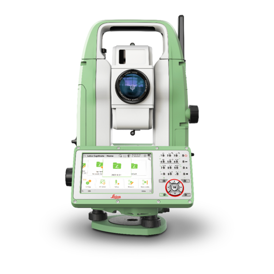
Page 25: Instrument Components
Instrument Components Instrument Compartment for SD card, USB memory stick components and USB cable ports part 1 of 2 Optical sight Detachable carrying handle with mounting screw Telescope, integrating EDM, EGL*, overview camera* Objective with integrated Electronic Distance Measurement (EDM). Exit for EDM laser beam Vertical drive Loudspeaker... -
Page 26: User Interface
User Interface Keyboard 3.1.1 Standard Keyboard Keyboard Display Alphanumeric keys ON/OFF Backspace Favourites Home 0016416_001 Arrow keys Enter Camera Keys Function Alphanumeric To type letters and numbers. keys Camera To capture an image with the camera. Leaves the current screen without storing any changes. -
Page 27: Optional Keyboard
Function Backspace Deletes the job in the centre of the job car- ousel. Key combinations Function Hold Fn while pressing Switch to Windows. Hold Fn while pressing Take a screenshot of the current screen. Hold Fn while pressing 1. Increase the screen brightness. Hold Fn while pressing 4. - Page 28 Keys Function Function keys Correspond to six softkeys that appear on F1 to F6 the bottom of the screen when the screen is activated. Function keys User definable keys to execute chosen com- F7 to F12 mands or access chosen screens. Alphanumeric To type letters and numbers.
-
Page 29: Operating Principles
Function Hold Fn while pressing 3. Increase the volume for acoustic warning sig- nals, beeps and keypresses on the instru- ment. Hold Fn while pressing 6. Decrease the volume for acoustic warning signals, beeps and keypresses on the instru- ment. Hold Fn while pressing 7. -
Page 30: Operation
Operation Instrument Setup Instrument setup step-by-step 0016417_001 ☞ Shield the instrument from direct sunlight and avoid uneven temper- atures around the instrument. Extend the tripod legs to allow for a comfortable working posture. Position the tripod above the marked ground point, centring it as good as possible. - Page 31 Leica USB drivers support Windows 7, Windows 8 (8.1) and Windows 10 oper- ating systems. Cables Leica USB drivers support: Name Description GEV223 USB data cable, 1.8 m, connects instrument to Mini-USB to GEV187 Y-cable, 2.0 m, allows connects instrument, external battery...
- Page 32 Run the Setup_Leica_USB_XXbit.exe to install the drivers necessary for Leica devices. Depending on the version (32bit or 64bit) of the operating system on your PC, you have to select between the three setup files following: Setup_Leica_USB_32bit.exe • • Setup_Leica_USB_64bit.exe Setup_Leica_USB_64bit_itanium.exe •...
-
Page 33: Power Functions
The InstallShield Wizard Completed window appears. Click Finish to exit the wizard. Connect to PC via USB Start the PC. cable step-by-step Plug the cable into the instrument. Turn on the instrument. Plug the cable into the USB port of the PC. Press the Windows Start button at the bottom left corner of the screen. -
Page 34: Batteries
It is normal for the battery to become warm during charging. Using the • chargers recommended by Leica Geosystems, it is not possible to charge the battery once the temperature is too high. For new batteries or batteries that have been stored for a long time •... -
Page 35: Working With The Memory Device
Open the lid of the communication compartment to access the com- munication ports. Slide the USB stick with the Leica logo facing you firmly into the USB host port until it clicks into position. ☞... -
Page 36: Distance Measurements - Guidelines For Correct Results
To remove the USB stick, open the lid of the compartment and slide the USB stick out of the port. Insert a SIM card step-by-step ☞ The SIM card is inserted into a slot behind the lid with the logo, almost in the middle of the housing. - Page 37 When a distance measurement is triggered, the EDM measures to the • object which is in the beam path at that moment. If a temporary obstruc- tion, for example a passing vehicle, heavy rain, fog or snow is between the instrument and the point to be measured, the EDM may measure to the obstruction.
-
Page 38: Check & Adjust
Check & Adjust Overview Description Leica Geosystems instruments are manufactured, assembled and adjusted to the best possible quality. Quick temperature changes, shock or stress can cause deviations and decrease the instrument accuracy. It is therefore recom- mended to check and adjust the instrument from time to time. This check and adjust can be done in the field by running through specific measurement pro- cedures. -
Page 39: Preparation
Vertical index error, related to the standing axis Horizontal collimation error, also called line of sight error Combined adjustment The following table explains the most common settings. procedure step-by- Leica Captivate - Home: Settings\TS instrument\Check & adjust step Check & Adjust Check & Adjust... - Page 40 & line of sight error Next Face I measurement ☞ Use a clean Leica standard prism as the target. Do not use a 360° prism. Aim the telescope accurately at a target at about 100 m distance. The target must be positioned within ±9°/±10 gon of the hori-...
-
Page 41: Adjusting The Tilting Axis Error
☞ The horizontal collimation error has to be determined before starting this pro- cedure. Access Leica Captivate - Home: Settings\TS instrument\Check & adjust Check & Adjust Select the option: Check & adjust the tilting axis Next Determination of tilt- The following table explains the most common settings. - Page 42 Face I measurement Aim the telescope accurately at a target at about 100 m dis- tance (or at least 20 m). The target must be positioned at least 27°/30 gon above or + 27° beneath the horizontal plane. The procedure can be started in any telescope face.
-
Page 43: Adjusting The Circular Level Of The Instrument And Tribrach
Select Redo to decline all measurements and to repeat all calibration runs. Adjusting the Circular Level of the Instrument and Tribrach Adjusting the circular level step-by-step 0016437_001 Place and secure the instrument into the tribrach and onto a tripod. Using the tribrach footscrews, level the instrument with the elec- tronic level. -
Page 44: Adjusting The Circular Level Of The Prism Pole
The laser plummet is located in the vertical axis of the instrument. Under nor- mal conditions of use, the laser plummet does not need adjusting. If an adjust- ment is necessary due to external influences, return the instrument to any Leica Geosystems authorised service workshop. Inspecting the laser plummet step-by-step 360°... -
Page 45: Servicing The Tripod
If the centre of the laser dot describes a perceptible circular move- ment or moves more than 3 mm away from the point which was first marked, an adjustment may be required. Inform your nearest Leica Geosystems authorised service centre. Depending on brightness and surface, the diameter of the laser dot can vary. -
Page 46: Care And Transport
Shipping When transporting the product by rail, air or sea, always use the complete orig- inal Leica Geosystems packaging, container and cardboard box, or its equiva- lent, to protect against shock and vibration. Shipping, transport of When transporting or shipping batteries, the person responsible for the prod-... -
Page 47: Cleaning And Drying
Cleaning and Drying Product and accesso- Blow dust off lenses and prisms. • ries Never touch the glass with your fingers. • • Use only a clean, soft, lint-free cloth for cleaning. If necessary, moisten the cloth with water or pure alcohol. Do not use other liquids; these may attack the polymer components. -
Page 48: Technical Data
Technical Data Angle Measurement Accuracy Available angular Standard deviation Display resolution accuracies Hz, V, ISO17123-3 ["] [mgon] ["] [°] [mgon] [mil] 0.0001 0.01 0.0001 0.01 0.0001 0.01 0.0001 0.01 Characteristics Absolute, continuous, diametric. Updates each 0.1 to 0.3 s. Distance Measurement with Reflectors Range Reflector Range A... -
Page 49: Distance Measurement Without Reflectors
Distance meas- std. dev. std. dev. Measurement uring mode ISO 17123-4, ISO 17123-4, time, typical [s] standard prism tape Once 1 mm + 1.5 ppm 3 mm + 2 ppm Once & fast 2 mm + 1.5 ppm 3 mm + 2 ppm Continuously 3 mm + 1.5 ppm 3 mm + 2 ppm... -
Page 50: Distance Measurement Reflector (>4.0Km)
Accuracy Standard ISO17123-4 Measure time, Measure time, measuring typical [s] maximum [s] 0m - 500m 2 mm + 2 ppm 3 - 6 >500m 4 mm + 2 ppm 3 - 6 Beam interruptions, severe heat shimmer and moving objects within the beam path can result in deviations of the specified accuracy. -
Page 51: Conformity To National Regulations
• Hereby, Leica Geosystems AG declares that the radio equipment type TS10 is in compliance with Directive 2014/53/EU and other applicable European Directives. The full text of the EU declaration of conformity is available at the fol- lowing Internet address: http://www.leica-geosystems.com/ce. -
Page 52: Dangerous Goods Regulations
Leica Geosystems has developed Guidelines on “How to carry Leica products” and “How to ship Leica products” with Lithium batteries. Before any transportation of a Leica product, we ask you to consult these guidelines on our web page (http://www.leica-geosystems.com/dgr) to ensure that you are in accordance with the IATA Dangerous Goods Regulations and that the Leica products can be transported correctly. - Page 53 USB device port Cable connections from USB devices for com- munication and data transfer Bluetooth Bluetooth connections for communication and data transfer WLAN (TS10) WLAN connection for Internet access, com- munication and data transfer LTE (optional) Internet access Pin assignments of...
- Page 54 Instrument dimensions 211.4 mm 223.7 mm 0016439_001 211.4 mm 223.7 mm 0016675_001 Weight Type Value Instrument 4.4 kg - 4.9 kg (depending on hardware con- figuration) Tribrach 760 g Battery GEB331 110 g Battery GEB361 340 g Tilting axis height Type Description Without tribrach...
- Page 55 ☞ Avoid dirt on cover glass. ☞ Avoid line-of-sight obstructions. The full spot needs to be on target. ☞ For best performance use the new Leica tripods. For older tripods, an upgrade of the screw is recommended. Power Type Description External supply voltage Nominal voltage 13.0 V DC...
-
Page 56: Scale Correction
Protection against water, dust and sand Type Protection IP66 (IEC 60529) instruments Humidity Type Protection Max 95% non condensing. instruments The effects of condensation are to be effectively counterac- ted by periodically drying out the instrument. Arctic model Operating temperature [°C] Storage temperature [°C] -35 to +50 -40 to +70... - Page 57 Atmospheric correction. • • Reduction to mean sea level. Projection distortion. • Atmospheric correc- The slope distance displayed is correct if the scale correction in ppm, mm/km, tion DD1 which has been entered corresponds to the atmospheric conditions prevailing at the time of the measurement. The atmospheric correction includes: •...
- Page 58 Atmospheric correction [ppm] Air pressure [mbar] Air temperature [°C] Relative humidity [%] 273.15 (7.5 * t/(237.3 + t)) + 0.7857 If the basic value of 60 % relative humidity as used by the EDM is retained, the maximum possible error in the calculated atmospheric correction is 2 ppm, 2 mm/km.
-
Page 59: Reduction Formulas
ASCII tances according to the formu- • • las. XML export Output without corrections for • • the atmospheric ppm ppm is stored as metadata • • Corrections are applied during later input, for example to Leica Infinity Technical Data... - Page 60 Formulas Mean Sea Level Instrument Reflector Slope distance Horizontal distance Height difference TS_110 The instrument calculates the slope distance, horizontal distance, height differ- ence in accordance with the following formulas: = D 0 · ( 1 + ppm · 10 ) + AC 002425_002 Displayed slope distance [m]...
- Page 61 These values are calculated as follows: · ∑ D i = 1 TS_114 Slope distance as arithmetic mean of all measurements å Single slope distance measurement Number of measurements ∑ ∑ ∑ - D) i = 1 i = 1 i = 1 n - 1 n - 1...
-
Page 62: Software Licence Agreement
Leica Geosystems. Such software is protected by copyright and other laws and its use is defined and regulated by... - Page 64 849702-1.0.0en Original text (849702-1.0.0en) Published in Switzerland © 2018 Leica Geosystems AG, Heerbrugg, Switzerland Leica Geosystems AG Heinrich-Wild-Strasse CH-9435 Heerbrugg Switzerland Phone +41 71 727 31 31 www.leica-geosystems.com...
Need help?
Do you have a question about the TS10 and is the answer not in the manual?
Questions and answers