
Related Manuals for Hunter PRO-C PC Series


Summary of Contents for Hunter PRO-C PC Series
- Page 1 PRO-C ® Residential and Light Commercial Irrigation Controller PC Series Modular Controller Indoor/Outdoor Models Owner’s Manual and Installation Instructions...
-
Page 2: Table Of Contents
CONNECTING A HUNTER “CLIK”WEATHER SENSOR ..15 SOLAR SYNC DELAY ............37 CONNECTING A HUNTER REMOTE ........17 CYCLE AND SOAK ............... 38 CONNECTING TO THE HUNTER SOLAR SYNC ....19 HUNTER QUICK CHECK CLIK-DELAY PROGRAMMING ..40 PROGRAMMING THE CONTROLLER CLEARING CONTROLLER’S MEMORY/RESETTING CONTROLLER .............. -
Page 3: Specifications
SPECIFICATIONS Operating Specifications Cabinet Dimensions • Station Count: Conventional wiring from 4 to 23 stations, Height: 9" (23 cm) Two-wire EZ Decoder option up to 32 stations Width: 10" (21.5 cm) Depth: 4 1/ 2" (10.9 cm) • Station Run Time: 1 minute to 6 hours on programs A, B, and C Outdoor cabinet is NEMA 3R, IP44 rated. -
Page 4: Pro-C Components
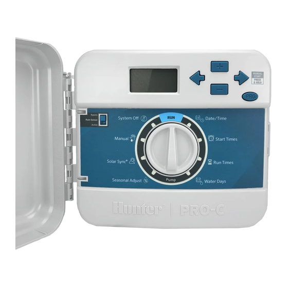
PRO-C COMPONENTS ⑦ ① ⑬ ⑭ ⑮ ⑱ ⑯ ⑰ ⑧ ⑫ ③ ② ⑤ ⑨ ⑪ ⑥ ④ ⑩... - Page 5 PRO-C COMPONENTS (CONTINUED) LCD Display Indicates various times, values, ① Main Display Running Indicates when watering occurs and programmed information ② Indicates watering will occur on Year Identifies current calendar year Rain Drop selected day ③ Month Identifies current calendar month Indicates watering will not occur Crossed Rain Drop ④...
- Page 6 PRO-C COMPONENTS (CONTINUED) ① ➉ ② ⑨ ③ ⑧ ④ ⑦ ⑤ ① ② ③ ④ ⑤ ⑥ ⑥ ⑦ ⑧ ⑨...
- Page 7 For additional surge protection, connect ⑦ Station a single station Ground Lug lug to earth ground Used to discontinue all programs Used to connect Hunter Solar Sync or and stop all watering until the dial ⑧ Sensor Terminals “Clik-type” sensors ⑩ System Off...
-
Page 8: Mounting The Controller To A Wall
MOUNTING THE CONTROLLER TO A WALL All necessary hardware is included for most installations. 1. Use the hole at the top of the controller as a reference and secure a 1" (25 mm) screw into the wall. Note: Install screw anchors if attaching to drywall or masonry wall. -
Page 9: Connecting Ac Power
CONNECTING AC POWER Indoor Cabinet To be performed by a licensed Route transformer cable through the hole on the bottom left electrician only. side of the controller and connect one Yellow Wire to each of the screws marked AC and the Green wire to GND. Always use UL listed ½”... -
Page 10: Installing Station Modules
INSTALLING STATION MODULES Installing PCM Modules The Pro-C controller is supplied with a factory-installed base module for up to 4 stations. Additional modules may be added in The Pro-C controller is designed with a simple-to-use “Power increments of 3 stations (PCM-300), 9 stations (PCM-900), or Lock”... -
Page 11: Connecting Station Wires
CONNECTING STATION WIRES 1. Route valve wires between control valve location and controller. 2. At valves, attach a common wire to either solenoid wire of all valves. This is most commonly a white colored wire. Attach a separate control wire to the remaining wire of each valve. -
Page 12: Connecting The Battery
CONNECTING THE BATTERY (OPTIONAL) NOTE: Warning: Risk of fire, explosion, and electric shock. Replace battery with CR 2032 type only. Use of a different battery has potential risk for fire, explosion, and electric shock. See owner’s manual for instructions. Connect a 9-volt alkaline battery (not included) to the battery terminals and place in the battery compartment in the front panel. -
Page 13: Connecting A Master Valve
Connecting a Master Valve (optional) Connect either wire from Master Valve to the P/MV terminal. Connect remaining wire to the “COM” (Common) terminal. P/MV NOTE: When using a PC-DM, the P/MV can be hardwired directly to the P/MV terminal or programmed to operate via the two-wire path. -
Page 14: Connecting A Pump Start Relay
Relay holding current draw must not exceed 0.28 amps (24 VAC). Do not connect the controller directly to the pump— damage to controller will result. For more information on the installation of a PSR, please visit the support page: https://hunter.direct/pumpstartrelay To pump 15' (4.5 m) minimum P/MV... -
Page 15: Connecting A Hunter "Clik"Weather Sensor
CONNECTING A HUNTER “CLIK” WEATHER SENSOR (NOT INCLUDED) A Hunter weather sensor or other micro-switch-type weather When the weather sensor sensors can be connected to the Pro-C. The purpose of this has deactivated automatic sensor is to stop automatic watering when weather conditions watering, “OFF”... - Page 16 CONNECTING A HUNTER “CLIK” WEATHER SENSOR (CONTINUED) Testing the Weather Sensor The Pro-C provides simplified testing of a rain sensor when the sensor is wired into the sensor circuit. You can manually test proper operation of the rain sensor by using the One - Touch Manual Start (see page 30).
-
Page 17: Connecting A Hunter Remote
The SmartPort wiring harness (included with all Hunter remotes) allows for fast and easy use of Hunter controls. Hunter remotes make it possible for you to operate the system without having to walk back and forth to the controller. To Install the SmartPort Connector 1. - Page 18 CONNECTING A HUNTER REMOTE (CONTINUED) (Blue) (White) (Red) NOTE: Any extension of the wiring on the SmartPort may result in an error message in the controller display and possible malfunction of the remote unit due to radio interference. In some situations, 1 2 ”...
-
Page 19: Connecting To The Hunter Solar Sync
In addition, the Solar Sync sensor includes watering schedule. a Hunter Rain-Clik® and Freeze-Clik® sensor that will shut For installation and programming instructions of your Hunter down your irrigation system when it rains and/or during Solar Sync, please refer to the Solar Sync owner’s manual... - Page 20 (ET), or the rate at Installing the Wireless Solar Sync which plants and turf use water, and also includes Hunter Rain-Clik and Freeze-Clik technology that will shut down Connect the Green and Black wire from the Wireless Solar irrigation when it rains and/or during freezing conditions.
- Page 21 CONNECTING A HUNTER SOLAR SYNC ET SENSOR Use the following table for choosing your region (reference below). Region You can use methods A, B, or C to help you choose which region is For accurate Solar Sync measurements, the controller needs to best for your area: be programmed for the average peak season ET for your region.
- Page 22 CONNECTING A HUNTER SOLAR SYNC ET SENSOR Water Adjustment Uninstalling a Solar Sync Sensor The Water Adjustment is a 1 to 10 scale that allows for easy If a Solar Sync sensor has been installed, then the seasonal adjust adjustment of the Seasonal Adjust value from the Solar Sync ET value used by the controller will be calculated from the weather Sensor.
- Page 23 CONNECTING A HUNTER SOLAR SYNC ET SENSOR Calibration/Setup After Solar Sync has been installed and programmed, allow the system to run for a few days at the initial setting. Because of the variety in site conditions (including sensor location, amount of direct sunlight available to the sensor, reflective heat from surrounding structures, etc), the initial setting may require adjustment to arrive at the desired performance.
-
Page 24: Setting The Current Date And Time
SETTING THE CURRENT DATE AND TIME 1. Turn the dial to the DATE/TIME position. 2. The current year will be flashing in the display. Use the + and - buttons to change the year. Push the→button to proceed to setting the month. 3. -
Page 25: Setting Program Start Times
SETTING PROGRAM START TIMES 1. Turn the dial to the START TIMES position. 2. Press the PRG button to select A, B, or C. 3. Use the + and - buttons to change the start time. (Advances in 15-minute increments.) One start time will activate all stations sequentially in that program. -
Page 26: Setting Station Run Times
SETTING STATION RUN TIMES 1. Turn the dial to the RUN TIMES position. 2. The display will show the last program selected (A, B, or C) the station number selected, and the run time for that station will be flashing. You can switch to another program by pressing the PRG button. -
Page 27: Setting A Watering Schedule
SETTING A WATERING SCHEDULE 1. Turn the dial to the WATER DAYS position. Selecting Odd or Even Days to Water This feature uses numbered day(s) of the month for watering 2. The display will show the last program selected (A, B, instead of specific days of the week (odd days: 1st, 3rd, 5th, etc.;... - Page 28 SETTING A WATERING SCHEDULE (CONTINUED) Selecting Interval Watering NOTE: If any days are selected as non- This feature is convenient if you want to have a more consistent water days at the bottom of the display, watering schedule without having to worry about the day of the the Interval Day watering will exclude week or the date.
-
Page 29: Options For Running Your Irrigation System
OPTIONS FOR RUNNING YOUR IRRIGATION SYSTEM Seasonal Adjustment Seasonal Adjust is used to make After programming is complete, turn the dial to the RUN global run time changes without re- position to enable automatic execution of all selected programming the entire controller. programs and start times. - Page 30 OPTIONS FOR RUNNING YOUR IRRIGATION SYSTEM (CONTINUED) One - Touch Manual Start and Advance You can also activate a program to water without using the dial. 1. With the dial in the RUN position, hold down the → button for 2 seconds.
-
Page 31: Using The Pro-C To Operate Outdoor Lighting
USING THE PRO-C TO OPERATE OUTDOOR LIGHTING (OPTIONAL) Connecting the FX Luminaire Transformer The Pro-C is capable of operating three separate lighting transformers equipped with the PXSync interface box. Connect wires from the first PXSync box to station output 1 (and the Common) on the Pro-C terminal. - Page 32 USING THE PRO-C TO OPERATE OUTDOOR LIGHTING (OPTIONAL) Creating a Lighting Program 1. Turn the dial to the START TIMES position. 2. Press and hold the PRG button for 6 seconds and observe the A, B, C programs moving. 3. L1 and a flashing “OFF” will appear, and the controller is ready to designate lighting programs.
-
Page 33: Advanced Features
ADVANCED FEATURES Set Pump/Master Valve Operation 4. Turn the dial back to the RUN position, at which time, OFF, a number and the DAYS icon The default is for all stations to have all remain on. the master valve/pump start circuit ON. The master valve/pump start can be set 5. -
Page 34: Hidden Features
HIDDEN FEATURES Program Customization Programmable Delay Between Stations The Pro-C is factory-configured with 3 independent programs This feature allows the user to insert a delay between when (A, B, C with four start times each) for different plant type one station turns off and the next station turns on. This is requirements. -
Page 35: Programmable Sensor Override
HIDDEN FEATURES (CONTINUED) Programmable Sensor Override The Pro-C allows the user to program the controller so that the A station that is running in the sensor override mode will display sensor disables watering on only desired stations. For example, the word “SENSOR” and flash the icon. patio gardens that have pots under overhangs and roofs may not receive water when it rains and will continue to need to be watered during periods of rain. -
Page 36: Total Run Time Calculator
HIDDEN FEATURES (CONTINUED) Total Run Time Calculator Easy Retrieve Program Memory ™ The Pro-C keeps a running total of each program’s station run The Pro-C is capable of saving the preferred watering program times. This feature provides a quick way to determine how long into memory for retrieval at a later time. -
Page 37: Solar Sync Delay
HIDDEN FEATURES (CONTINUED) Solar Sync Delay for Pro-C To change the existing Delay days setting: The delay feature is accessible only after the installation 1. Open the Solar Sync Delay menu by pressing the + button and of the Solar Sync. The Solar Sync Delay feature allows the user rotating the dial to Solar Sync Settings and release the to postpone seasonal adjustment changes from being made + button. -
Page 38: Cycle And Soak
HIDDEN FEATURES (CONTINUED) Cycle and Soak Setting the Cycle Time: Initially Station 1 will be displayed. To access other stations, The Cycle and Soak feature allows you to split a station’s press the ← or → button. run time into more usable, shorter watering durations. This feature is useful when applying water to slopes and tight soils Once the desired station is displayed, use the + or - button to because it automatically applies water more slowly, helping to... - Page 39 HIDDEN FEATURES (CONTINUED) Accessing the Soak Menu: Once the desired station is displayed, the user can use the + or - button to increase or decrease the Soak time. Once the desired Cycle times for each station have been The user can set the Soak time from 1 minute to 4 hours programmed, the Cycle time can be accessed by pressing the in 1-minute increments.
-
Page 40: Hunter Quick Check Clik-Delay Programming
ERR symbol preceded by the station number will momentarily flash on the controller LCD display. After the Hunter Quick Check completes running this circuit diagnostic procedure, the controller returns to the automatic watering mode. -
Page 41: Clik Delay Instructions
Clik Delay feature with 5. Return the dial to the RUN position. Clik Delay is set. Hunter Wind-Clik, Freeze-Clik, Soil- Clik, and freeze component of Solar Sync and After a Clik Event ends (rain sensor changes from wet to dry) the... -
Page 42: Troubleshooting Guide
TROUBLESHOOTING GUIDE Problem Cause Solution The controller repeats itself or Too many start times (Programming Error). Only one start time per active program continuously waters, even when it is required. Refer to “Setting Program should not be on (cycling repeatedly). Start Times”... - Page 43 TROUBLESHOOTING GUIDE (CONTINUED) Problem Cause Solution The display reads “SENSOR OFF.” The rain sensor is interrupting irrigation Slide the Rain Sensor switch on front or the sensor jumper is not installed. panel to the BYPASS position to bypass rain sensor circuit, or install the sensor jumper.
- Page 44 Certificate of Conformity to European Directives Hunter Industries declares that the irrigation controller Model Pro-C complies with the standards of the European Directives of “electromagnetic compatibility” Directive 2014/30/EU and “low voltage” Directive 2014/35/EU. Senior Regulatory Compliance Engineer FCC Notice This controller generates radio frequency energy and may If necessary, the user should consult the dealer or an experienced cause interference to radio and television reception.
- Page 45 NOTES...
- Page 46 NOTES...
- Page 47 NOTES...
- Page 48 1940 Diamond Street, San Marcos, California 92078 USA Learn more. Visit hunterindustries.com LIT-605-US C 3/20 © 2020 Hunter Industries Inc. Hunter, the Hunter logo, and all other trademarks are property of Hunter Industries, registered in the U.S. and other countries.
Need help?
Do you have a question about the PRO-C PC Series and is the answer not in the manual?
Questions and answers