Table of Contents
Advertisement
Quick Links
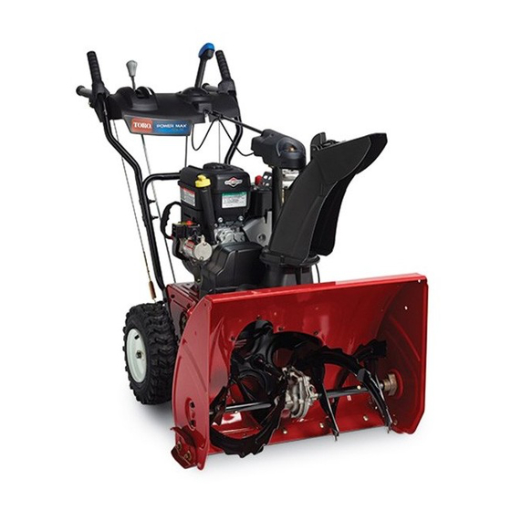
Power Max 724/826 OE Snowthrower
Model No. 37772-Serial No. 315000001 and Up
Model No. 37775-Serial No. 315000001 and Up
WARNING
CALIFORNIA
Proposition 65 Warning
This product contains a chemical or chemicals
known to the State of California to cause cancer,
birth defects, or reproductive harm.
The engine exhaust from this product
contains chemicals known to the State of
California to cause cancer, birth defects,
or other reproductive harm.
Introduction
This machine is intended to be used by residential
homeowners or professional, hired operators. It is
designed for removing snow from paved surfaces, such
as driveways and sidewalks, and other surfaces for
traffic on residential or commercial properties. It is not
designed for removing materials other than snow, nor is
a model with a pivoting scraper designed for clearing off
gravel surfaces.
Read this information carefully to learn how to operate and
maintain your machine properly and to avoid injury and
machine damage. You are responsible for operating the
machine properly and safely.
You may contact Toro directly at www.Toro.com for machine
and accessory information, help finding a dealer, or to register
your machine.
Whenever you need service, genuine Toro parts, or additional
information, contact an Authorized Service Dealer or Toro
Customer Service and have the model and serial numbers of
your machine ready. Figure 1 identifies the location of the
model and serial numbers on the machine. Write the numbers
in the space provided.
© 2014-The Toro® Company
8111 Lyndale Avenue South
Bloomington, MN 55420
This manual identifies potential hazards and has safety
messages identified by the safety alert symbol (Figure 2),
which signals a hazard that may cause serious injury or death
if you do not follow the recommended precautions.
This manual uses 2 words to highlight information.
Important calls attention to special mechanical information
and Note emphasizes general information worthy of special
attention.
Contents
Introduction .................................................................. 1
Safety ........................................................................... 2
Register at www.Toro.com.
g018884
Figure 1
1. Model and serial number location
Model No.
Serial No.
Figure 2
1. Safety alert symbol
Training ................................................................. 3
Preparation............................................................. 3
Operation............................................................... 3
Clearing a Clogged Discharge Chute .......................... 4
Maintenance and Storage.......................................... 4
Toro Snowthrower Safety ......................................... 4
Safety and Instructional Decals ................................. 5
Original Instructions (EN)
All Rights Reserved *3385-226* A
Printed in the USA
Form No. 3385-226 Rev A
Operator's Manual
Advertisement
Table of Contents

Related Manuals for Toro Power Max 724


Summary of Contents for Toro Power Max 724
-
Page 1: Table Of Contents
You are responsible for operating the Figure 2 machine properly and safely. 1. Safety alert symbol You may contact Toro directly at www.Toro.com for machine and accessory information, help finding a dealer, or to register your machine. This manual uses 2 words to highlight information. -
Page 2: Safety
Setup ................7 Operating Tips ............18 1 Installing the Upper Handle........7 Maintenance ..............19 2 Installing the Traction Control Linkage ....8 Recommended Maintenance Schedule(s) ......19 3 Installing the Chute ..........9 ................19 4 Installing the Chute Control Rod ......10 Preparing for Maintenance........19 5 Checking the Engine Oil Level .......10 Checking the Engine Oil Level .........19... -
Page 3: Training
Training eyes from foreign objects that may be thrown from the machine. • Read, understand and follow all instructions on the machine and in the manual(s) before operating this Operation machine. Be thoroughly familiar with the controls and the proper use of the machine. Know how to stop the •... -
Page 4: Clearing A Clogged Discharge Chute
Run the machine a few minutes after throwing snow to prevent freeze-up of the rotor blades. Toro Snowthrower Safety The following list contains safety information specific to Toro machines or other safety information that you must know. • Rotating auger/impeller can amputate or injure fingers or hands. -
Page 5: Safety And Instructional Decals
Safety and Instructional Decals Important: Safety and instruction decals are located near areas of potential danger. Replace damaged decals. 121–6817 1. Cutting dismemberment, impeller and cutting dismemberment, auger hazards—keep bystanders a safe distance from the snowthrower. 121–6823 1. Fast 3. Slow 2. - Page 6 Briggs & Stratton Part No. 273676 3. Fast 1. Stop 2. Slow Briggs & Stratton Part No. 277588 1. Primer 3. Ignition key out Briggs & Stratton Part No. 275949 (Engine—Stop) 1. Choke on (Choke) 2. Choke off (Run) 2. Ignition key in (Engine—Run) Briggs &...
-
Page 7: Setup
Setup Loose Parts Use the chart below to verify that all parts have been shipped. Procedure Description Qty. Handle bolts Curved washers Install the upper handle. Locknuts Hairpin cotter Install the traction control linkage. Flat washer Carriage bolt Install the chute. Flat washer Carriage bolts Install the chute control rod. -
Page 8: Installing The Traction Control Linkage
Installing the Traction Control Linkage g019378 Figure 6 Parts needed for this procedure: Hairpin cotter 6. Pull up on the speed control rod and insert the trunnion Flat washer into the hole in the speed selector lever (Figure 5). Note: If the trunnion does not fit into the hole Procedure when you lift up on the speed control rod, rotate the trunnion upward or downward on the speed control... -
Page 9: Installing The Chute
Installing the Chute Parts needed for this procedure: Carriage bolt Flat washer Procedure 1. Place the chute on the frame and the align the discharge chute mount to the chute support. g019379 Figure 8 1. Carriage bolt 3. Nut 2. Flat washer 2. -
Page 10: Installing The Chute Control Rod
Installing the Chute Control Parts needed for this procedure: Carriage bolts Locknuts Procedure g018885 1. Unwrap the Quick Stick and rotate it so that it is Figure 10 upright and in the center. 2. Hold the blue trigger cap down and pull the lever fully 5. -
Page 11: Checking The Tire Pressure
Note: Before starting the engine, check the oil level and add oil if necessary. Use automotive detergent oil with an API service classification of SF, SG, SH, SJ, SL, or higher. Refer to your engine owner's Checking the Tire Pressure manual. -
Page 12: Product Overview
Product Overview 3. Squeeze the left hand (traction) lever to the hand-grip (Figure 14). Figure 14 The machine should move rearward. If the machine does not move or moves forward, complete the following: g018887 A. Release the traction lever and stop the engine. B. -
Page 13: Operation
Filling the Fuel Tank DANGER Gasoline is extremely flammable and explosive. A Figure 17 fire or explosion from gasoline can burn you and 1. Snow cleanout tool (attached to the handle) others. • To prevent a static charge from igniting the gasoline, place the container and/or machine Operation on the ground before filling, not in a vehicle or... -
Page 14: Starting The Engine
Starting the Engine 1. Check the engine oil level. Refer to Checking the Engine Oil Level in Maintenance. 2. Turn the fuel shutoff valve 1/4 turn counterclockwise to open it (Figure 21). Figure 21 g018889 Figure 20 1. 1-1/2 inch (3.8 cm) 3. - Page 15 4. Firmly push in the primer with your thumb 2 times 7. Start the machine pulling the recoil starter or pressing (15°F or -9°C or above) or 4 times (below 15°F or the electric-starter button (Figure 26). -9°C), holding the primer in for a second before releasing it each time (Figure 23).
-
Page 16: Stopping The Engine
Operating the Traction Drive CAUTION If you leave the machine plugged into a CAUTION power outlet, someone can inadvertently start the machine and injure people or damage If the traction drive is not properly adjusted, the property. machine may move in the direction opposite of what you intended, causing injury and/or property Unplug the power cord whenever you are not damage. -
Page 17: Operating The Auger/Impeller Drive
Operating the Auger/Impeller Drive 1. To engage the auger/ impeller drive, squeeze the right hand (auger/ impeller) lever to the handgrip (Figure 31). Figure 32 Moving the Discharge Chute Figure 31 Hold the blue trigger cap down and move the Quick Stick to the left to move the discharge chute to the left;... -
Page 18: Unclogging The Discharge Chute
from freezing. Stop the engine, wait for all moving parts to stop, and remove all ice and snow from the machine. • With the engine off, pull the recoil starter handle several times and push the electric-starter button once to prevent the recoil and electric starters from freezing up. -
Page 19: Maintenance
• Have an Authorized Service Dealer inspect and replace the traction drive belt and/or the auger/impeller drive belt, if necessary. Important: You can find more information about maintaining and servicing your machine at www.Toro.com. Important: Refer to your engine operator's manual for additional maintenance procedures. For engine adjustments, repairs, or warranty service not covered in this manual, contact an Authorized Briggs &... -
Page 20: Checking And Adjusting The Skids And Scraper
Checking and Adjusting the Yearly—Inspect the traction cable and adjust or replace it if necessary. Skids and Scraper If the machine does not drive in the forward or reverse speeds Service Interval: Yearly—Check the skids and the scraper or it drives when you release the traction lever, adjust the and adjust them if necessary. -
Page 21: Checking And Adjusting The Auger/Impeller Cable
Checking and Adjusting the Checking the Auger Gearbox Auger/Impeller Cable Oil Level Service Interval: After the first 2 hours—Inspect the Service Interval: Yearly—Check the auger gearbox oil and auger/impeller cable and adjust it if add oil if necessary. necessary. 1. Move the machine to a level surface. Yearly—Inspect the auger/impeller cable and adjust 2. -
Page 22: Changing The Engine Oil
Changing the Engine Oil Lubricating the Hex Shaft Service Interval: After the first 5 hours—Change the engine Service Interval: Yearly—Lubricate the hex shaft. oil. Lightly lubricate the hex shaft yearly with automotive engine Yearly—Change the engine oil. oil (Figure 44). If possible, run the engine just before changing the oil because warm oil flows better and carries more contaminants. -
Page 23: Replacing The Spark Plug
9. Install the back cover and return the machine to the operating position. Replacing the Spark Plug Service Interval: Yearly—Replace the spark plug. Use a Champion QC12YC or equivalent spark plug. Note: To access the spark plug, you must first remove the upper snow hood (Figure 46). -
Page 24: Adjusting The Discharge Chute Latch
Adjusting the Discharge Chute Storage Latch WARNING If the discharge chute does not lock into the desired position or does not unlock so that you can move it to another • Gasoline vapors can explode. position, adjust the discharge chute latch. •... -
Page 25: Troubleshooting
Troubleshooting Problem Possible Cause Corrective Action Electric starter does not turn (electric-start 1. The power cord is disconnected at the 1. Connect the power cord to the outlet models only) outlet or the machine. and/or the machine. 2. The power cord is worn, corroded, or 2. - Page 26 5. Unclog the discharge chute. 6. The auger/impeller drive belt is loose 6. Install and/or adjust the auger/impeller or is off the pulley. drive belt; refer to www.Toro.com for servicing information or take the machine to an Authorized Service Dealer.
- Page 27 Notes:...
- Page 28 Notes:...
- Page 29 Notes:...
- Page 30 Such use will not reduce the warranty obligations of The Toro Company. 10. Add-on or modified parts that are not approved by The Toro Company may not be used. The use of a non-approved add-on or modified parts by the purchaser will be grounds for disallowing a warranty claim.
- Page 31 Warranted Parts The following emission warranty parts are covered, to the extent these parts were present on the Toro engine/equipment and/or Toro supplied fuel system: 1. Fuel System Parts • Carburetor and internal parts • Cold starting enrichment (primer or choke) •...
- Page 32 Countries Other than the United States or Canada Customers who have purchased Toro products exported from the United States or Canada should contact their Toro Distributor (Dealer) to obtain guarantee policies for your country, province, or state. If for any reason you are dissatisfied with your Distributor's service or have difficulty obtaining guarantee information, contact the Toro importer.