Table of Contents
Advertisement
Quick Links
Advertisement
Table of Contents

Related Manuals for Sanyo PLC-XU101


Summary of Contents for Sanyo PLC-XU101
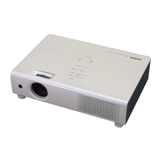
- Page 1 Multimedia Projector PLC-XU101 MODEL PLC-XU101K Owner’s Manual...
-
Page 2: Features And Design
Features and Design This Multimedia Projector is designed with the most advanced technology for portability, durability, and ease of use. This projector utilizes built-in multimedia features, a palette of 16.77 million colors, and matrix liquid crystal display (LCD) technology. ◆ ◆... -
Page 3: Table Of Contents
Table of Contents Features and Design ....2 Computer Input .....26 Input Source Selection Table of Contents . -
Page 4: To The Owner
A BREAKDOWN OR A DISASTER. IF THE PROJECTOR countries and not applied to the countries in the other area of the world. COMES IN CONTACT WITH OIL OR CHEMICALS, IT MAY BECOME DETERIORATED. Your SANYO product is designed and manufactured with high quality materials and components which can be recycled and reused. -
Page 5: Safety Instructions
Safety Instructions All the safety and operating instructions should be read Do not install the projector near the ventilation duct of air- before the product is operated. conditioning equipment. Read all of the instructions given here and retain them for This projector should be operated only from the type of later use. -
Page 6: Air Circulation
Safety Instructions Air Circulation Moving the Projector Openings in the cabinet are provided for ventilation. To When moving the projector, close the slide shutter and ensure reliable operation of the product and to protect it retract adjustable feet to prevent damage to the lens and from overheating, these openings must not be blocked cabinet. -
Page 7: Installing The Projector In Proper Directions
Safety Instructions Installing the Projector in Proper Directions Use the projector properly in specified positions. Improper positioning may reduce the lamp life and result in severe accident or fire hazard. This projector can project the picture upward, downward, or backward, perpendicular to the plane of the screen as shown in the figure below. -
Page 8: Compliance
Model Number(s) : PLC-XU101 Trade Name : Sanyo Responsible party : SANYO FISHER COMPANY Address : 21605 Plummer Street, Chatsworth, California 91311 U.S.A. Telephone No. : (818)998-7322 AC Power Cord Requirement The AC Power Cord supplied with this projector meets the requirement for use in the country you purchased it. -
Page 9: Part Names And Functions
Part Names and Functions Front q Zoom Ring w Infrared Remote Receiver e Focus Ring r Projection Lens t Slide Shutter Lever y Top Controls and Indicators u Exhaust Vent CAUTION Hot air is exhausted from the exhaust vents. Do not put heat-sensitive objects near this side. -
Page 10: Rear Terminal
Part Names and Functions Rear Terminal q SERVICE PORT y AUDIO IN This jack is used to service the projector. Connect the audio output signal from video equipment connected to t or o to this jack. For a w COMPUTER IN 2/COMPONENT IN mono audio signal (a single audio jack), connect it Connect the computer or component video (or to the L (MONO) jack (p.16). -
Page 11: Top Control
Part Names and Functions Top Control q LAMP REPLACE indicator u WARNING indicator Lights yellow when the projection lamp reaches its –Lights red when the projector detects an abnormal end of life (pp.54, 60). condition. –Blinks red when the internal temperature of the w ON/STAND–BY button projector exceeds the operating range (pp.51, 60). -
Page 12: Remote Control
Part Names and Functions Remote Control q ON/STAND-BY button Turn the projector on or off. (pp.19, 20) w VIDEO button Select VIDEO input source. (pp.24, 35) e COMPUTER button Select COMPUTER input source. (pp24, 26, 36) r MENU button Open or close the On-Screen Menu. (p21) t Point ( VOLUME + / –... -
Page 13: Remote Control Battery Installation
Part Names and Functions Remote Control Battery Installation Open the battery Install new batteries into Replace the compartment lid. the compartment. compartment lid. Two AA size batteries For correct polarity (+ and –), be sure battery terminals are in contact with pins compartment. -
Page 14: Installation
Installation Positioning the Projector For projector positioning, see the figures below. The projector should be set perpendicularly to the plane of the screen. ✔ Notes: •The brightness in the room has a great influence on picture quality. It is recommended to limit ambient lighting in order to obtain the best image. -
Page 15: Connecting To A Computer
Installation Connecting to a Computer Cables used for connection • VGA Cable (Mini D-sub 15 pin)* • Audio Cables (*One cable is supplied; other cables are not supplied with the projector.) Audio Output Monitor Output Monitor Input External Audio Equipment Audio Input VGA cable VGA cable... -
Page 16: Connecting To Video Equipment
Installation Connecting to Video Equipment Cables used for connection • Video and Audio Cable (RCA x 3) • S-VIDEO Cable • Audio Cable (Cables are not supplied with the projector.) Composite Video and Audio Output S-video Output (Video) External Audio Equipment Video and S-video cable audio cable... -
Page 17: Connecting To Component Video Equipment
Installation Connecting to Component Video Equipment Cables used for connection • Audio Cables • Scart-VGA Cable • Component Cable • Component-VGA Cable (Cables are not supplied with the projector.) RGB Scart Component Video Output 21-pin Output (Y, Pb/Cb, Pr/Cr) Audio Output Component cable External Audio Equipment... -
Page 18: Connecting The Ac Power Cord
Installation Connecting the AC Power Cord This projector uses nominal input voltages of 100–120 V or 200–240 V AC and it automatically selects the correct input voltage. It is designed to work with single-phase power systems having a grounded neutral conductor. To reduce the risk of electrical shock, do not plug into any other type of power system. -
Page 19: Basic Operation
Basic Operation Turning On the Projector Complete peripheral connections (with a computer, VCR, etc.) before turning on the projector. Connect the projector’s AC power cord into an AC outlet. The POWER indicator lights red. Open the slide shutter by sliding the slide shutter lever. -
Page 20: Turning Off The Projector
Basic Operation Turning Off the Projector Press the ON/STAND-BY button on the top control or on the remote control, and “Power off?” appears on the screen. Press the ON/STAND-BY button again to turn off the projector. The POWER indicator starts to blink red, and the cooling fans keep running. -
Page 21: How To Operate The On-Screen Menu
Basic Operation How to Operate the On-Screen Menu The projector can be adjusted or set via the On-Screen Top Control Menu. For each adjustment and setting procedure, refer to the respective sections in this manual. MENU button Press the MENU button on the top control or the POINT buttons remote control to display the On-Screen Menu. -
Page 22: Menu Bar
Basic Operation Menu Bar For detailed functions, see Menu Tree on pp.58, 59. For computer source Screen Menu Guide Window PC System Menu Image Select Menu Setting Menu Show the selected Used to select Used to select an image Used to adjust size of Used to set the image. -
Page 23: Zoom And Focus Adjustment
Basic Operation Zoom and Focus Adjustment Rotate the Zoom Ring to zoom in and out. Zoom Ring Rotate the Focus Ring to adjust the focus of the image. Focus Ring Sound Adjustment Top Control Direct Operation VOLUME+/- buttons Volume Press the VOLUME+/– buttons on the top control or on the remote control to adjust the volume. -
Page 24: Remote Control Operation
Basic Operation Remote Control Operation For some frequently used operations, using the remote control is advisable. Just pressing one of the buttons enables you to make the operation, and no need for calling up the On-Screen Menu. Remote Control COMPUTER / VIDEO button Press the COMPUTER or VIDEO button on the remote COMPUTER /VIDEO... - Page 25 Basic Operation AUTO PC button Remote Control Press the AUTO PC button on the remote control to operate the Auto PC function. Volume +/- For more detail, see 28. buttons POINT ed (See p23) buttons D.ZOOM buttons AUTO PC button Press the D.ZOOM buttons on the remote control to zoom IMAGE button in and zoom out the images.
-
Page 26: Computer Input
Computer Input Input Source Selection Top Control Direct Operation Choose either Computer 1 or Computer 2 by pressing the COMPUTER 2 button COMPUTER 1 button or COMPUTER 2 button on the top control or press the COMPUTER button on the remote COMPUTER 1 button control. -
Page 27: Computer System Selection
Computer Input Computer System Selection This projector automatically tunes to various types of computers based on VGA, SVGA, XGA, SXGA, WXGA or UXGA with its Multi-scan system and Auto PC Adjustment. If Computer is selected as a signal source, this projector automatically detects the signal format and tunes to project a proper image without any additional setting. -
Page 28: Auto Pc Adjustment
Computer Input Auto PC Adjustment Auto PC Adjustment function is provided to automatically adjust Fine sync, Total dots, Horizontal, and Vertical to conform to your computer. Auto PC Adjustment function can be operated as follows. Direct Operation Remote Control The Auto PC adjustment function can be operated directly by pressing the AUTO PC button on the remote control unit. -
Page 29: Manual Pc Adjustment
Computer Input Manual PC Adjustment Some computers employ special signal formats which may not be tuned by Multi-scan system of this projector. Manual PC Adjustment enables you to precisely adjust several parameters to match those signal formats. The projector has five independent memory areas to memorize those parameters manually adjusted. It allows you to recall the setting for a specific computer. - Page 30 Computer Input Display area H Use the Point buttons to adjust the horizontal area displayed by this projector. Display area V Use the Point buttons to adjust the vertical area displayed by this projector. Reset Move the red frame pointer to an item and To reset the adjusted data, select Reset and press the press the SELECT SELECT button.
-
Page 31: Image Mode Selection
Computer Input Image Mode Selection Remote Control Direct Operation IMAGE button Select the desired image mode from among Dynamic, Dynamic Standard, Real, Blackboard (Green), Image 1, Image 2, Image 3, and Image 4 by pressing the IMAGE button on the remote control. -
Page 32: Image Adjustment
Computer Input Image Adjustment Press the MENU button to display the On-Screen Image Adjust Menu Menu. Press the Point buttons to move the red frame pointer to the Image Adjust Menu icon. Image Adjust Menu icon Use the Point buttons to move the red frame Move frame pointer to the desired item and then press the SELECT... -
Page 33: Screen Size Adjustment
Computer Input Store To store the adjusted data, select Store and press the SELECT button. Use the Point ed buttons to select one Image Mode Menu from Image 1 to 4 and press the SELECT button. Move the red frame A confirmation box appears and then select [Yes]. - Page 34 Computer Input Custom Adjust the screen scale and position manually with this function. Press the SELECT button at Custom and the “Custom” is displayed on the screen for a few seconds and then the Aspect dialog box appears. Scale H/V.... Adjust the Horizontal/Vertical screen scale. H&V....
-
Page 35: Video Input
Video Input Input Source Selection (Video, S-Video) Top Control Direct Operation Choose Video by pressing the VIDEO button on the top VIDEO button control or the remote control. Before using these buttons, correct input source should be selected through menu operation as described below. REMOTE CONTROL VIDEO button Input Menu icon... -
Page 36: Input Source Selection (Component, Rgb Scart 21-Pin)
Video Input Input Source Selection (Component, RGB Scart 21-pin) Top Control Direct Operation COMPUTER 2 button Choose Computer 2 by pressing the COMPUTER 2 button on the top control or press the COMPUTER button on the remote control. Before using these buttons, correct input source should be selected through Menu operation as described below. -
Page 37: Video System Selection
Video Input Video System Selection Press the MENU button to display the On-Screen Menu. Press the Point buttons to move the red frame pointer to the AV System Menu icon. Use the Point buttons to move the red arrow pointer to the desired system and then press the SELECT button. -
Page 38: Image Mode Selection
Video Input Image Mode Selection IMAGE button Direct Operation Remote Control Dynamic Select the desired image mode from among Dynamic, Standard, Cinema, Blackboard (Green), Image 1, Image 2, Image 3, and Image 4 by pressing the IMAGE button on the Standard remote control. -
Page 39: Image Adjustment
Video Input Image Adjustment Press the MENU button to display the On-Screen Image Adjust Menu Menu. Press the Point buttons to move the red frame pointer to the Image Adjust Menu icon. Use the Point buttons to move the red frame Image Adjust Menu icon pointer to the desired item and then press the SELECT Move... - Page 40 Video Input Sharpness Press the Point button to decrease the sharpness of the image; press the Point button to increase the sharpness of the image (from 0 to 15). Gamma Use the Point buttons to adjust the gamma value to obtain a better balance of contrast (from 0 to 15).
-
Page 41: Screen Size Adjustment
Video Input Screen Size Adjustment This projector has the picture screen resize function, which enables you to customize the image size. Press the MENU button to display the On-Screen Screen Menu Menu. Use the Point buttons to move the red frame pointer to the Screen Menu icon. -
Page 42: Setting
Setting Setting This projector has Setting menu that allows you to set up Setting Menu (Language) the other various functions described as follows; Press the MENU button to display the On-Screen Menu. Press the Point buttons to move the red Set the red frame Setting Menu pointer to the item... - Page 43 Setting Logo (Logo and Logo PIN code lock settings) This function allows you to customize the screen logo with Logo select, Capture, and Logo PIN code lock functions. ✔ Note: When On is selected in Logo PIN code lock function, Logo select and Capture functions cannot be selected.
- Page 44 Setting Logo PIN code lock Logo PIN code lock This function prevents an unauthorized person from changing the screen logo. Off.... The screen logo can be changed freely from the Logo Menu (p.43). On .... The screen logo cannot be changed without a Logo PIN code.
- Page 45 Setting Ceiling Ceiling When this function is set to “On,” the picture will be top/bottom and left/right reversed. This function is used to project the image from a ceiling-mounted projector. Rear Rear When this function is set to “On,” the picture will be left/right reversed.
- Page 46 Setting Power management Power management For reducing power consumption as well as maintaining the lamp life, the Power management function turns off the projection lamp when the input signal is interrupted and no button is pressed for a certain period. Time left before Lamp is off.
- Page 47 Setting Remote control Remote control This projector provides two different remote control codes; the factory-set, initial code (Code 1) and the secondary code (Code 2). This switching function prevents remote control interference when operating several projectors or video Press and hold equipment at the same time.
- Page 48 Setting PIN code lock PIN code lock This function prevents the projector from being operated by an unauthorized person and provides the following settings for security options. Off..the projector is not locked with the PIN code. On1 ..require to enter the PIN code every time turning on the projector.
- Page 49 Setting This function provides the following options in the cooling fans’ operation when the projector is turned off (p.20). L1..Normal operation L2..Slower and lower-sound than the normal operation (L1), but it takes more time to cool the projector down.
- Page 50 Setting Filter counter Filter counter This function is used to set a frequency for the filter cleaning. When the projector reached a specified time between cleanings, a Filter warning icon appears on the screen, notifying the cleaning is necessary. After cleaning the filter, be sure to select RESET and set the timer.
-
Page 51: Maintenance And Cleaning
Maintenance and Cleaning Warning Indicator The WARNING indicator shows the state of the function which protects the projector. Check the state of the WARNING indicator and the POWER indicator to take proper maintenance. The projector is shut down and the WARNING Top Control indicator is blinking red. -
Page 52: Cleaning The Filter
Maintenance and Cleaning Cleaning the Filter Filter prevents dust from accumulating on the optical elements inside the projector. Should the filter becomes clogged with dust particles, it will reduce cooling fans’ effectiveness and may result in internal heat buildup and adversely affect the life of the projector. -
Page 53: Slide Shutter
Maintenance and Cleaning Slide Shutter Slide Shutter is provided to protect the surface of the lens Slide Shutter Lever against scratches and dirt. When you are not using the projector, close the Slide Shutter. To open or close, use the Slide Shutter Lever on the top of the cabinet. -
Page 54: Lamp Replacement
Replacement lamp can be ordered through your dealer. When ordering a projection lamp, give the following information to the dealer. ● Model No. of your projector : PLC-XU101/PLC-XU101K ● Replacement Lamp Type No. : POA-LMP111 (Service Parts No. 610 333 9740) -
Page 55: Resetting The Lamp Counter
Maintenance and Cleaning Resetting the Lamp Counter Be sure to reset the Lamp counter after the lamp is replaced. When the Lamp counter is reset, the LAMP REPLACE indicator stops lighting and the Lamp replacement icon disappears. Press the MENU button to display the On-Screen Menu. -
Page 56: Appendix
Appendix Troubleshooting Before calling your dealer or service center for assistance, check the items below once again. –Make sure you have properly connected the projector to peripheral equipment as described on page15-17. –Make sure all equipment is connected to AC outlet and the power is turned on. –When you operate the projector with a computer and it does not project an image, restart the computer. - Page 57 Appendix Some displays are not seen –Check the Display function. (See page 42.) during the operation. PIN code dialog box appears at start-up. –PIN code lock is being set. Input a PIN code (1234 or numbers you have set). (See pages 19 and 48.) The Remote Control does not work.
-
Page 58: Menu Tree
Appendix Menu Tree Computer Input / Video Input Input Computer 1 Computer 2 RGB( Analog ) Go to System Component Go to System RGB( Scart ) Quit Video Auto Go to System Video Go to System S-Video Go to System Quit ✽N/A not applicable... - Page 59 Appendix Video Input Setting Setting Language System Auto English Finnish 1080i German Polish 1035i French Hungarian 720p Italian Romanian 575p Spanish Russian 480p Portuguese Chinese 575i Dutch Korean 480i Swedish Japanese System Auto Quit Quit Keystone Store / Reset SECAM Blue back On / Off NTSC...
-
Page 60: Indicators And Projector Condition
Appendix Indicators and Projector Condition Check the indicators for projector condition. Indicators Projector Condition LAMP WARNING POWER REPLACE red/green yellow The projector is off. (The AC power cord is unplugged.) The projector is preparing for stand-by or the projection lamp is ✽... -
Page 61: Compatible Computer Specifications
Appendix Compatible Computer Specifications The projector can basically accept the signal from all computers with the V, H-Frequency mentioned below and less than 140 MHz of Dot Clock. ON-SCREEN H-Freq. V-Freq. ON-SCREEN H-Freq. V-Freq. RESOLUTION RESOLUTION DISPLAY (kHz) (Hz) DISPLAY (kHz) (Hz) VGA 1... -
Page 62: Technical Specifications
Appendix Technical Specifications Mechanical Information Projector Type Multi-media Projector Dimensions (W x H x D) 13.15” x 3.07” x.9.13” (334 mm x 78 mm x 232 mm) (Not including adjustable feet) Net Weight 7.5 lbs (3.3 kg) Feet Adjustment 0˚ to approx. 9˚ Panel Resolution LCD Panel System 0.8"... -
Page 63: Optional Parts
Appendix Accessories Owner's Manual (CD-ROM) Quick Reference Guide AC Power Cord Remote Control and Batteries VGA Cable PIN Code Label ● The specifications are subject to change without notice. ● LCD panels are manufactured to the highest possible standards. Even though 99.99% of the pixels are effective, a tiny fraction of the pixels (0.01% or less) may be ineffective by the characteristics of the LCD panels. -
Page 64: Configurations Of Terminals
Appendix Configurations of Terminals COMPUTER INPUT/COMPONENT INPUT/MONITOR OUTPUT TERMINAL (ANALOG) Terminal : Analog RGB (Mini D-sub 15 pin) Red (R/Cr) Input / Output Green (G/Y) Input / Output Ground (Vert.sync.) Blue (B/Cb) Input / Output Ground ----- DDC data Ground (Horiz.sync.) Horiz. -
Page 65: Pin Code Number Memo
Appendix PIN Code Number Memo Write down the PIN code number in the column below and keep it with this manual securely. If you forgot or lost the number and unable to operate the projector, contact the service station. PIN Code Lock No. Factory default set No: 1 2 3 4* Logo PIN Code Lock No. - Page 66 KL6AC SANYO Electric Co., Ltd.