Advertisement
INSTRUCTION MANUAL
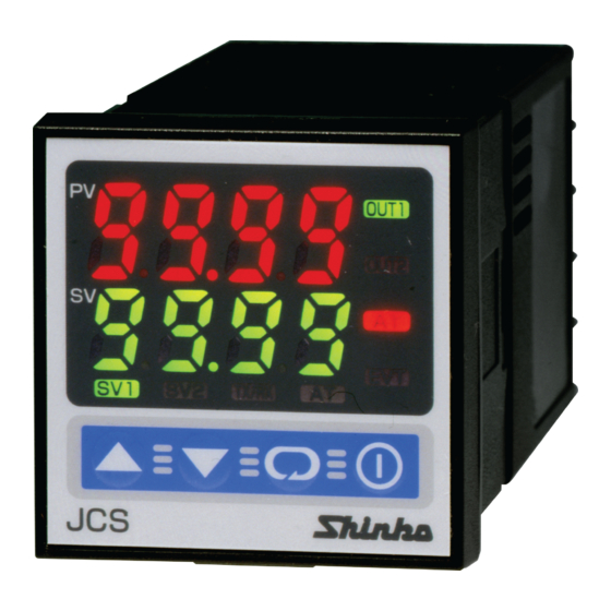
Micro-computer based digital indicating controller
To prevent accidents arising from the misuse of this controller, please ensure the operator receives this manual.
SAFETY PRECAUTIONS
• To ensure safe and correct use, thoroughly read and understand this manual before using this instrument.
• This instrument is intended to be used for industrial machinery, machine tools and measuring equipment. Verify correct
usage after consulting purpose of use with our agency or main office. (Never use this instrument for medical purposes
with which human lives are involved.)
• External protection devices such as protection equipment against excessive temperature rise, etc. must be installed, as
malfunction of this product could result in serious damage to the system or injury to personnel. Also proper periodic
maintenance is required.
• This instrument must be used under the conditions and environment described in this manual. Shinko Technos Co., Ltd.
does not accept liability for any injury, loss of life or damage occurring due to the instrument being used under
conditions not otherwise stated in this manual.
Caution with respect to Export Trade Control Ordinance
To avoid this instrument from being used as a component in, or as being utilized in the manufacture of weapons of
mass destruction (i.e. military applications, military equipment, etc.), please investigate the end users and the final use
of this instrument. In the case of resale, ensure that this instrument is not illegally exported.
Warning
• To prevent an electric shock or fire, only Shinko or other qualified service personnel may handle the inner assembly.
• To prevent an electric shock, fire or damage to the instrument, parts replacement may only be undertaken by
Shinko or other qualified service personnel.
Caution
• This instrument should be used according to the specifications described in the manual.
If it is not used according to the specifications, it may malfunction or cause a fire.
• Be sure to follow the warnings, cautions and notices. Not doing so could cause serious injury or malfunction.
• Specifications of the JCS-33A and the contents of this instruction manual are subject to change without notice.
• This instrument is designed to be installed through a control panel. If it is not, measures must be taken to ensure
that the operator cannot touch power terminals or other high voltage sections.
• Be sure to turn the power supply to the instrument OFF before cleaning this instrument.
• Use a soft, dry cloth when cleaning the instrument. (Alcohol based substances may tarnish or deface the unit.)
• As the display section is vulnerable, do not strike or scratch it with a hard object.
• Any unauthorized transfer or copying of this document, in part or in whole, is prohibited.
• Shinko Technos CO., LTD. is not liable for any damage or secondary damage(s) incurred as a result of using
this product, including any indirect damage.
1. Model
1.1 Model
J C S – 3 3
Control action
A1
Control output
(OUT1)
Input
Supply voltage
Option
*1: Alarm types (9 types and No alarm action) and Energized/Deenergized can be selected by keypad.
*2: Thermocouple, RTD, DC current, and DC voltage can be selected by keypad.
*3: Supply voltage 100 to 240V AC is standard. When ordering 24V AC/DC, enter "1" after the input code.
,
3
A
R
S
A
M
1
A2
W (5A)
W (10A)
W (20A)
W (50A)
DT
C5
SM
LA
BK
TC
Series name: JCS-33A (W48 x H48 x D95mm)
PID
Alarm type can be selected by keypad. *1
Relay contact: 1a
Non-contact voltage (for SSR drive): 12
DC current: 4 to 20mA DC
Multi-range
*2
100 to 240V AC (standard)
24V AC/DC
*3
Alarm 2 (A2) *1
Heater burnout alarm
Heating/Cooling control,
Control output (OUT2)
Serial communication (RS-485)
SV1/SV2 external selection
Loop break alarm
Color Black
Terminal cover
1
和文は裏面をご覧下さい。
JCS-33A
JCS31JE1 2007.09
+2
V DC
0
CT rated current: 5A
CT rated current: 10A
CT rated current: 20A
CT rated current: 50A
Non-contact relay
Advertisement
Table of Contents

Related Manuals for Shinko JCS-33A


Summary of Contents for Shinko JCS-33A
- Page 1 Warning • To prevent an electric shock or fire, only Shinko or other qualified service personnel may handle the inner assembly. • To prevent an electric shock, fire or damage to the instrument, parts replacement may only be undertaken by Shinko or other qualified service personnel.
-
Page 2: Name And Functions
(32 to 122 ), Humidity: 35 to 85%RH (No icing, no condensation) If the JCS-33A is installed through the control panel, the ambient temperature of the JCS-33A must be kept to under 50 . Otherwise the life of electronic parts (especially electrolytic capacitors) of the JCS-33A will be shortened. - Page 3 3.2 External dimensions (Scale: mm) Screw type mounting bracket Gasket 11.5 (Fig. 3.2-1) 3.3 Panel cutout (Scale: mm) Lateral close mounting n x 48-3 +0.5 n: Number of units mounted Caution: If lateral close mounting is used for the controller, IP66 specification (Dust-proof/Drip-proof) may be compromised, and all warranties will be invalidated.
- Page 4 (Fig. 4-1) Notice • The terminal block of the JCS-33A is designed to be wired from the left side. The lead wire must be inserted from the left side of the terminal, and fastened by the terminal screw. • Dotted lines show options.
- Page 5 5. Operation 5.1 Operation flowchart Output MV (manipulated Control output OFF [ PV/SV display mode variable) indication or Auto/Manual control (Approx. 3sec) (Approx. 3sec) (Approx. 3sec) [Main setting mode] [Sub setting mode] [Auxiliary function setting mode 1] [Auxiliary function setting mode 2] AT/Auto-reset Set value lock Input type...
- Page 6 Wire the power terminals only. After the power is turned on, the sensor input characters and temperature unit are indicated on the PV display and the input range high limit value is indicated on the SV display for approximately 3 seconds. (For DC current and voltage input, scaling high limit value is indicated.) (Table 5.1-1) During this time, all outputs and the LED indicators are in OFF status.
- Page 7 Integral time setting 200 seconds • Sets integral time for OUT1. • Setting the value to 0 disables the function. • Not available if OUT1 is in ON/OFF action. • Auto-reset can be performed when PD is control action (I=0). •...
- Page 8 : 9600bps, : 19200bps Parity selection Even parity • Selects the parity. • Not available if the C5 option is not added or if Shinko protocol is selected during the Communication protocol selection. • : No parity, : Even parity,...
- Page 9 Decimal point place selection No decimal point • Selects decimal point place. • Available only for DC inputs • : No decimal point : 1 digit after decimal point : 2 digits after decimal point : 3 digits after decimal point PV filter time constant setting 0.0 seconds •...
- Page 10 A2 action Energized/Deenergized selection Energized • Selects Energized/Deenergized for A2. • Not available if A2 option is not added or if No alarm action is selected during A2 type selection • : Energized, : Deenergized A1 hysteresis setting • Sets hysteresis for A1. •...
-
Page 11: Operation
After the unit is mounted to the control panel and wiring is completed, operate the unit following the procedures below. (1) Switch power supply to the JCS-33A ON. • For approx. 3sec after the power is switched ON, the sensor input characters and the temperature unit are indicated on the PV display, and input range high limit value is indicated on the SV display. - Page 12 7.3 EVT (Heater burnout alarm) action Output Alarm action Heater burnout alarm value Indicator Small Large Load current Unlit 7.4 Alarm action High limit alarm Low limit alarm High/ Low limits alarm A1 hysteresis A1 hysteresis A1 hysteresis Alarm action A1 value A1 value -A1 value...
- Page 13 7.7 OUT2 (Heating/Cooling control) action (When setting Dead band) ( Cooling P -band ) Heating P - band Dead band Control Heating ( Cooling action action action ) Relay contact output (OUT1) Cycle action is performed according to deviation . Non - contact 12/ 0 V DC...
-
Page 14: Specifications
9. Specifications 9.1 Standard specifications Mounting : Flush Setting : Input system using membrane sheet key Display PV display : Red LED 4 digits, character size 10.2 x 4.9 mm (H x W) SV display : Green LED 4 digits, character size 8.8 x 4.9 mm (H x W) Accuracy (Setting and Indication): Thermocouple : Within 0.2% of each input span... - Page 15 Insulation resistance : 10M or more, at 500V DC Dielectric strength : 1.5kV AC for 1minute between input terminal and power terminal 1.5kV AC for 1minute between output terminal and power terminal Supply voltage : 100 to 240V AC 50/60Hz, 24V AC/DC 50/60Hz Allowable voltage fluctuation: 100 to 240V AC: 85 to 264V AC, 24V AC/DC: 20 to 28V AC/DC Power consumption : Approx.
- Page 16 [Burnout] When the thermocouple or RTD input is burnt out, OUT1 and OUT2 are turned off (for DC current output type, OUT1 low limit value, OUT2 low limit value) and PV display flashes “ ”. [Self-diagnosis] The CPU is monitored by a watchdog timer, and if an abnormal status is found on the CPU, the controller is switched to warm-up status.
-
Page 17: Troubleshooting
When the data from the programmable controller is out of the SV high limit or low limit value, the JCS-33A ignores the value, and performs the control with the previous value. The control desired value adds SVTC bias value to the value received by the SVTC command. - Page 18 2. Set it to a suitable value. • If you have any inquiries, please consult our agency or the vender where you purchased the unit. SHINKO TECHNOS CO., LTD. OVERSEAS DIVISION Reg. Office 2-5-1, Senbahigashi, Minoo, Osaka, Japan http://www.shinko-technos.co.jp...
Need help?
Do you have a question about the JCS-33A and is the answer not in the manual?
Questions and answers