
Related Manuals for HIKVISION DS-KV8213-WME1


Summary of Contents for HIKVISION DS-KV8213-WME1
- Page 1 DS-KV8213-WME1 DS-KV8413-WME1 DS-KV8113-WME1 Video Intercom Villa Door Station User Manual...
- Page 2 BREACH OF CONTRACT, TORT (INCLUDING NEGLIGENCE), PRODUCT LIABILITY, OR OTHERWISE, IN CONNECTION WITH THE USE OF THE PRODUCT, EVEN IF HIKVISION HAS BEEN ADVISED OF THE POSSIBILITY OF SUCH DAMAGES OR LOSS. YOU ACKNOWLEDGE THAT THE NATURE OF INTERNET PROVIDES FOR INHERENT SECURITY RISKS, AND HIKVISION SHALL NOT TAKE ANY RESPONSIBILITIES FOR ABNORMAL OPERATION, PRIVACY LEAKAGE OR OTHER DAMAGES RESULTING FROM CYBER-ATTACK, HACKER ATTACK, VIRUS INSPECTION, OR OTHER INTERNET SECURITY RISKS;...
- Page 3 DS-KV8x13-WME1 Video Intercom Villa Door Station User Manual Symbol Conventions The symbols that may be found in this document are defined as follows. Symbol Description Indicates a hazardous situation which, if not avoided, will or could result in death or Danger serious injury.
- Page 4 DS-KV8x13-WME1 Video Intercom Villa Door Station User Manual • Do not aim the device at the sun or extra bright places. A blooming or smear may occur otherwise (which is not a malfunction however), and affecting the endurance of sensor at the same time. •...
- Page 5 DS-KV8x13-WME1 Video Intercom Villa Door Station User Manual FCC Conditions This device complies with part 15 of the FCC Rules. Operation is subject to the following two conditions: • This device may not cause harmful interference. • This device must accept any interference received, including interference that may cause undesired operation.
-
Page 6: Table Of Contents
DS-KV8x13-WME1 Video Intercom Villa Door Station User Manual Contents 1. Appearance ............................... 10 1.1. Single-Button Villa Door Station ......................10 1.2. Two-Button Villa Door Station ......................11 1.3. Four-Button Villa Door Station ......................12 2. Terminal and Wiring Description ........................ 13 2.1. - Page 7 DS-KV8x13-WME1 Video Intercom Villa Door Station User Manual Video & Audio Settings Video Parameters ................28 Audio Parameters ........................29 5.6. Image Settings ............................29 Display Settings ......................... 29 OSD Settings ..........................31 Target Cropping ......................... 31 5.7. Event Settings ............................32 Motion Detection ........................
- Page 8 DS-KV8x13-WME1 Video Intercom Villa Door Station User Manual Permission Settings ........................45 6.5. Video Intercom Settings........................45 Receive Call from Door Station ....................46 Release Notice .......................... 46 Search Video Intercom Information ..................47 Upload Armed Information ......................48 Appendix: Communication Matrix and Device Command................. 49 Table of Figures Figure 1, Single-Button Villa Door Station Appearance ..................
- Page 9 DS-KV8x13-WME1 Video Intercom Villa Door Station User Manual Figure 27, Motion Detection ..........................32 Figure 28, Event Linkage ............................. 33 Figure 29, Weekly Schedule ..........................34 Figure 30, Holiday Schedule ..........................34 Figure 31, Device ID Settings ..........................35 Figure 32, Press Button to Call ..........................36 Figure 33, Number Settings ..........................
-
Page 10: Appearance
DS-KV8x13-WME1 Video Intercom Villa Door Station User Manual 1. Appearance 1.1. Single-Button Villa Door Station Figure 1, Single-Button Villa Door Station Appearance Table 1-1 Description Description Microphone Indicator Unlock (Green)/Call (Orange)/Communicate (White) Camera Loudspeaker Button Card Reading Area IR Light MicroSD Card Slot (Reserved) and Debugging Port Terminals UM DS-KV8x13-WME1 Villa Door Station 062321NA... -
Page 11: Two-Button Villa Door Station
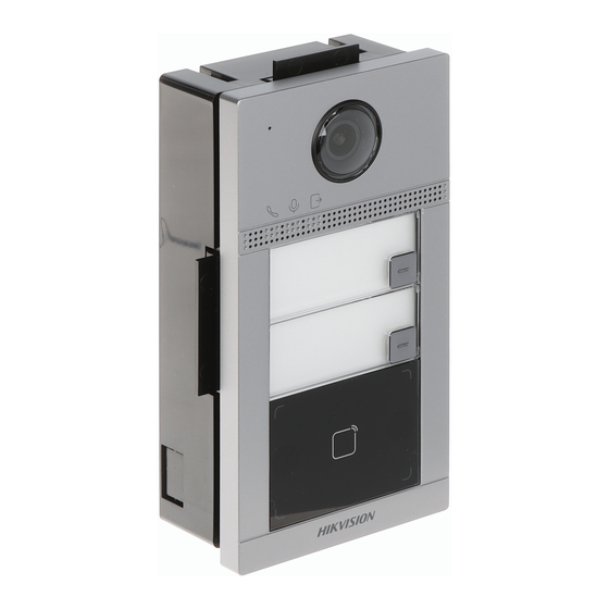
DS-KV8x13-WME1 Video Intercom Villa Door Station User Manual 1.2. Two-Button Villa Door Station Figure 2, Two-Button Villa Door Station Appearance Table 1-2 Description Description Microphone Indicator: Unlock (Green)/Call (Orange)/Communicate (White) Camera Loudspeaker Button Card Reading Area IR Light MicroSD Card Slot (Reserved) and Debugging Port Terminals UM DS-KV8x13-WME1 Villa Door Station 062321NA... -
Page 12: Four-Button Villa Door Station
DS-KV8x13-WME1 Video Intercom Villa Door Station User Manual 1.3. Four-Button Villa Door Station Figure 3, Four-Button Villa Door Station Appearance Table 1-3 Description Description Microphone Indicator: Unlock (Green)/Call (Orange)/Communicate (White) Camera Loudspeaker Button Card Reading Area IR Light MicroSD Card Slot (Reserved) and Debugging Port Terminals UM DS-KV8x13-WME1 Villa Door Station 062321NA... -
Page 13: Terminal And Wiring Description
DS-KV8x13-WME1 Video Intercom Villa Door Station User Manual 2. Terminal and Wiring Description 2.1. Terminal Description Figure 4, Terminal Description Table 2-1 Description of Terminal and Interfaces Name Interface Description Door Lock Relay Output 2 (NC) COM2 Common Interface Door Lock Relay Output 2 (NO) Grounding DOOR Door Lock Relay Output 1 (NO) -
Page 14: Door Contact Wiring
DS-KV8x13-WME1 Video Intercom Villa Door Station User Manual NOTE: Terminal NC1/COM1 is set as default for accessing magnetic lock/electric bolt. Terminal NO1/COM1 is set as default for accessing electric strike. To connect electric lock in terminal NO2/COM2/NC2, it is required to set the output of terminal NO2/COM2/NC2 to be electric lock with the iVMS-4200 client software. -
Page 15: Installation
DS-KV8x13-WME1 Video Intercom Villa Door Station User Manual 3. Installation NOTE: Make sure the device in the package is in good condition and all the assembly parts are included. Make sure your power supply matches your door station. Make sure all the related equipment is powered off during the installation. Check the product specification for the installation environment. -
Page 16: Surface Mounting Without Protective Shield
DS-KV8x13-WME1 Video Intercom Villa Door Station User Manual Figure 10, Mounting Template Align the protective shield with the mounting template. Secure the mounting plate on the wall with four supplied screws according to the screw holes. Secure the device on the mounting plate with the four supplied set screws. Affix the cover onto the device with the screw. -
Page 17: Figure 11, Mounting Template
DS-KV8x13-WME1 Video Intercom Villa Door Station User Manual Figure 12, Mounting Template Secure the mounting plate on the wall with four supplied screws according to the screw holes. Secure the device on the mounting plate with the four supplied set screws. Fix the cover onto the device with the screw. -
Page 18: Activation
DS-KV8x13-WME1 Video Intercom Villa Door Station User Manual 4. Activation 4.1. Activate Device via Web You are required to activate the device first by setting a strong password for it before you can use the device. Default parameters of the door station are as follows: Default IP Address: 192.0.0.65 •... -
Page 19: Edit Network Parameters
DS-KV8x13-WME1 Video Intercom Villa Door Station User Manual Create a password, and confirm the password. STRONG PASSWORD RECOMMENDED − We highly recommend that you create a strong password of your own choosing (using a minimum of eight characters, including at least three of the following categories: upper case letters, lower case letters, numbers, and special characters) in order to increase the security of your product. -
Page 20: Remote Configuration Via Web
DS-KV8x13-WME1 Video Intercom Villa Door Station User Manual 5. Remote Configuration via Web 5.1. Live View Enter the device IP address in the browser address bar, and press Enter to enter the login page. Enter the user name and password and click Login, or click Live View, to enter the Live View page. Figure 14, Live View •... -
Page 21: Device Management
DS-KV8x13-WME1 Video Intercom Villa Door Station User Manual 5.3. Device Management You can manage the linked device on the page. Click Device Management to enter the settings page. Figure 16, Device Management Add Device • Click Add to add the indoor station or sub door station. Enter the parameters and click OK to add. ... -
Page 22: Local Parameters Settings
DS-KV8x13-WME1 Video Intercom Villa Door Station User Manual → Internet Options → Security to disable Protected Mode. NOTE: Run the browser, click Local Parameters Settings You can configure the parameters of the live view, record files, and capture pictures. The record files and captured pictures are the ones you record and capture by using a Web browser. -
Page 23: System Settings
DS-KV8x13-WME1 Video Intercom Villa Door Station User Manual 5.5. System Settings Follow the instructions below to configure the system settings, include System Settings, Maintenance, Security, User Management, etc. Click System to enter the settings page. Basic Information: Click System Settings → Basic Information to enter the settings page. On the page, •... -
Page 24: Figure 17, Online Users
DS-KV8x13-WME1 Video Intercom Villa Door Station User Manual Set and confirm the encryption password. Click OK to export parameters. • Import Config. File: Click Browse Icon to select the configuration file. Click Import and enter the encryption password to import. •... -
Page 25: Network Settings Tcp/Ip Settings
DS-KV8x13-WME1 Video Intercom Villa Door Station User Manual • Arming/Disarming Information Click User Management → Arming/Disarming Information to view the information. Click Refresh to get the present information. Network Settings TCP/IP Settings TCP/IP settings must be properly configured before you operate the device over a network. The device supports IPv4. -
Page 26: Sip Setting
DS-KV8x13-WME1 Video Intercom Villa Door Station User Manual Figure 21, Port Settings Set the device ports. HTTP Port: The default port number is 80, and it can be changed to any port no. that is not occupied. HTTPS Port: The default port number is 443, and it can be changed to any port no. that is not occupied. -
Page 27: Ftp Settings
DS-KV8x13-WME1 Video Intercom Villa Door Station User Manual FTP Settings Steps Click Network → Advanced → FTP to enter the settings page. Figure 23, FTP Settings Check Enable FTP. Select Server Type. Input the Server IP Address and Port. Configure the FTP Settings, and the user name and password are required for the server login. Set the Directory Structure, Parent Directory, and Child Directory. -
Page 28: Video & Audio Settings Video Parameters
DS-KV8x13-WME1 Video Intercom Villa Door Station User Manual Check the Enable checkbox to enable the function. Select the Platform Access Mode. NOTE: Hik-Connect is an application for mobile devices. With the app, you can view a live image of the device, receive alarm notifications, etc. Create a Stream Encryption/Encryption for the device. -
Page 29: Audio Parameters
DS-KV8x13-WME1 Video Intercom Villa Door Station User Manual Max. Bitrate: Set the max. bitrate from 32 to 16384 Kbps. A higher value corresponds to higher video quality, but more bandwidth is required. Video Encoding: The device supports H.264. I Frame Interval: Set the I Frame Interval from 1 to 400. Click Save to save the settings. -
Page 30: Figure 24, Display Settings
DS-KV8x13-WME1 Video Intercom Villa Door Station User Manual Figure 26, Display Settings Select the Format. Set the display parameters. WDR: Wide Dynamic Range can be used when there is a high contrast of the bright area and the dark area of the scene. Brightness: The image brightness, which ranges from 1 to 100. -
Page 31: Osd Settings
DS-KV8x13-WME1 Video Intercom Villa Door Station User Manual Figure 28, Backlight 1) Check the checkbox to enable BLC. 2) Select BLC Area. Click Save to enable the settings. OSD Settings You can customize the camera name, time/date format, display mode, and OSD size displayed on the live view. -
Page 32: Event Settings
DS-KV8x13-WME1 Video Intercom Villa Door Station User Manual NOTE: You can select the Cropping Resolution as 704*576, 1280*720, or 1920*1080. You can zoom in to or zoom out of the image by selecting Cropping Resolution after clicking Save. 5.7. Event Settings Motion Detection Motion detection detects moving objects in the configured surveillance area, and a series of actions can be taken when an alarm is triggered. -
Page 33: Event Linkage
DS-KV8x13-WME1 Video Intercom Villa Door Station User Manual Notify Surveillance Center: Send an exception or alarm signal to the remote management software when an event occurs. Click Save to enable the settings. Event Linkage Steps Click Event → Basic Event → Event Linkage to enter the settings page. Figure 30, Event Linkage Set the Major Type as Device Event or Door Event. - Page 34 DS-KV8x13-WME1 Video Intercom Villa Door Station User Manual Select Call Type. Set Weekly Schedule. 1) Click Weekly Schedule. Figure 31, Weekly Schedule 2) Drag mouse to set the schedule according to the actual needs. 3) Optional: Click the copy icon to copy the schedule to other days according to the actual needs. 4) Click Save.
-
Page 35: Intercom Settings
DS-KV8x13-WME1 Video Intercom Villa Door Station User Manual NOTE: The holiday schedule has higher priority than the weekly schedule when you set the two schedules at the same time. 5.8. Intercom Settings Device ID Configuration Steps Click Device ID Settings to enter the page. Figure 33, Device ID Settings Select the device type from the drop-down list, and set the corresponding information including Building No., Floor No., Door Station No., Community No., and Unit No. -
Page 36: Time Parameters
DS-KV8x13-WME1 Video Intercom Villa Door Station User Manual Click Save to enable the settings. Time Parameters Go to Intercom → Time Parameters to enter the page. Configure Max. Call Duration, Max. Message Duration, Max. Ring Duration, and click Save. NOTE: Max. -
Page 37: Access Control Settings Door Parameters
DS-KV8x13-WME1 Video Intercom Villa Door Station User Manual Figure 35, Number Settings Click Add, set the Room No. and SIP numbers in the pop-up dialog box. Access Control Settings Door Parameters Steps Click Access Control → Door Parameters to enter the settings page. Figure 36, Door Parameters Select the door and edit the door name. - Page 38 DS-KV8x13-WME1 Video Intercom Villa Door Station User Manual Figure 37, Elevator Control Check to enable elevator control function. Select an Elevator No., and select an elevator controller type for the elevator. Set the Negative Floor. Set the Interface Type as RS-485 or Network Interface, and enable the elevator control. RS-485: Make sure you connected the door station to the elevator controller with an RS-485 cable.
-
Page 39: Configuration Via Client Software
DS-KV8x13-WME1 Video Intercom Villa Door Station User Manual 6. Configuration via Client Software 6.1. Device Management Device management includes device activation, add device, edit device, delete device, etc. After running the iVMS-4200 software, add the video intercom devices to the client software for remote configuration and management. -
Page 40: Add Device By Ip Address
DS-KV8x13-WME1 Video Intercom Villa Door Station User Manual Add Device by IP Address Steps Click +Add to pop up the adding devices dialog box. Select IP/Domain as Adding Mode. Enter corresponding information. Click Add. Add Device by IP Segment You can add many devices at once whose IP addresses are among the IP segment. Steps Click +Add to pop up the dialog box. -
Page 41: Modify And Delete Organization
DS-KV8x13-WME1 Video Intercom Villa Door Station User Manual The added organization will be the sub-organization of the upper-level organization. NOTE: Up to 10 levels of organizations can be created. Modify and Delete Organization You can select the added organization and click to modify its name. -
Page 42: Modify And Delete Person
DS-KV8x13-WME1 Video Intercom Villa Door Station User Manual 1) Click Credential → Card. Take the person’s photo with the collection device. 1) Click + to pop up the Add Card dialog. 2) Select Normal Card as Card Type. 3) Enter the Card No. 4) Click Read and the card will be issued to the person. -
Page 43: Get Person Information From Device
DS-KV8x13-WME1 Video Intercom Villa Door Station User Manual Steps Exporting Person: You can export the added persons’ information in Microsoft Excel format to a local PC. • After adding the person, you can click Export Person to pop up the following dialog. Click ... -
Page 44: Issue Card In Batch
DS-KV8x13-WME1 Video Intercom Villa Door Station User Manual Issue Card in Batch You can issue multiple cards for a person with no card issued in batch. Steps Click Batch Issue Cards to enter the dialog page. All the added persons with no card issued will display in the Person(s) with No Card Issued list. -
Page 45: Permission Settings
DS-KV8x13-WME1 Video Intercom Villa Door Station User Manual Result: After issuing the card to the person, the person and card information will display on the Person(s) with Card Issued list. Permission Settings Add Permissions Steps AccessControlInfo → Access Group to enter the page. On the main page, click Click +Add to pop up the adding dialog box. -
Page 46: Receive Call From Door Station
DS-KV8x13-WME1 Video Intercom Villa Door Station User Manual Receive Call from Door Station Steps Select the client software in the page to start calling the client and an incoming call dialog will pop up in the client software. Click Answer to answer the call, or click Hang Up to decline the call. After you answer the call, you will enter the In Call page. -
Page 47: Search Video Intercom Information
DS-KV8x13-WME1 Video Intercom Villa Door Station User Manual Click View to select the picture. Click Send. NOTE: Up to 63 characters are allowed in the Subject field. Up to six pictures in jpg format can be added to one notice. The maximum size of one picture is 512 KB. -
Page 48: Upload Armed Information
DS-KV8x13-WME1 Video Intercom Villa Door Station User Manual Optional: Click Export to export the call logs to your PC. Search Notice Steps On the Video Intercom page, click Notice to enter the page. Set the search conditions, including notice type, start time, and end time. Type: Select Advertising Information, Property Information, Alarm Information, or Notice Information as Type according to your needs. -
Page 49: Appendix: Communication Matrix And Device Command
Device Command Scan the following QR code to get the device common serial port commands. Note that the command list contains all commonly used serial ports commands for all Hikvision access control and video intercom devices. Figure 43, Device Command...
Need help?
Do you have a question about the DS-KV8213-WME1 and is the answer not in the manual?
Questions and answers