HIKVISION DS-KV8102-IM User Manual
Hide thumbs
Also See for DS-KV8102-IM:
- Quick start manual (31 pages) ,
- User manual (87 pages) ,
- User manual (6 pages)
Table of Contents
Advertisement
Advertisement
Table of Contents

Related Manuals for HIKVISION DS-KV8102-IM


Summary of Contents for HIKVISION DS-KV8102-IM
- Page 1 Video Intercom Door Station (V Series) User Manual UD.6L0206D1104A01...
- Page 2 Trademarks and other Hikvision marks are the property of Hikvision and are registered trademarks or the subject of applications for the same by Hikvision and/or its affiliates. Other trademarks mentioned in this manual are the properties of their respective owners. No right of license is given to use such trademarks without express permission.
- Page 3 FOR LOSS OF BUSINESS PROFITS, BUSINESS INTERRUPTION, SECURITY BREACHES, OR LOSS OF DATA OR DOCUMENTATION, IN CONNECTION WITH THE USE OF OR RELIANCE ON THIS MANUAL, EVEN IF HIKVISION HAS BEEN ADVISED OF THE POSSIBILITY OF SUCH DAMAGES. SOME JURISDICTIONS DO NOT ALLOW THE EXCLUSION OR LIMITATION OF LIABILITY OR CERTAIN DAMAGES, SO SOME OR ALL OF THE ABOVE EXCLUSIONS OR LIMITATIONS MAY NOT APPLY TO YOU.
-
Page 4: Regulatory Information
Video Intercom Door Station·User Manual Regulatory Information FCC Information Please take attention that changes or modification not expressly approved by the party responsible for compliance could void the user’s authority to operate the equipment. FCC compliance: This equipment has been tested and found to comply with the limits for a Class B digital device, pursuant to part 15 of the FCC Rules. - Page 5 Video Intercom Door Station·User Manual 2006/66/EC (battery directive): This product contains a battery that cannot be disposed of as unsorted municipal waste in the European Union. See the product documentation for specific battery information. The battery is marked with this symbol, which may include lettering to indicate cadmium (Cd), lead (Pb), or mercury (Hg).
- Page 6 Video Intercom Door Station·User Manual Safety Instruction These instructions are intended to ensure that user can use the product correctly to avoid danger or property loss. The precaution measure is divided into Warnings and Cautions: Warnings: Neglecting any of the warnings may cause serious injury or death. Cautions: Neglecting any of the cautions may cause injury or equipment damage.
- Page 7 Video Intercom Door Station·User Manual Exposing the equipment to direct sun light, low ventilation or heat source such as heater or radiator is forbidden (ignorance can cause fire danger). Do not aim the device at the sun or extra bright places. A blooming or smear may occur otherwise (which is not a malfunction however), and affecting the endurance of sensor at the same time.
-
Page 8: Table Of Contents
Video Intercom Door Station·User Manual Table of Contents 1 Overview ...................... 1 1.1 Introduction ......................1 1.2 Main Features ......................1 2 Appearance ....................2 2.1 Appearance of DS-KV8X02-IM ................. 2 2.2 Appearance of DS-KV8102-XP ................. 3 3 Typical Application ..................4 3.1 Typical Application of DS-KV8X02-IM .............. - Page 9 Video Intercom Door Station·User Manual 8.3.2 Adding by IP Address or IP Segment............... 28 8.4 Remote Configuration ................... 29 8.4.1 System ......................29 8.4.2 Video Intercom ....................36 8.4.3 Network ......................40 8.4.4 Video Display ....................42 9 Setting the Door Station via iVMS-4200 ............. 44 9.1 System Configuration .....................
-
Page 10: Overview
Video Intercom Door Station·User Manual 1 Overview 1.1 Introduction The door station (V series) can realize functions such as video intercom, access control, one-card system, zone alarm, and visitor messages to form a complete smart community video intercom solution. The door station (V series) is mainly applied in the villa, and can works as door station, outer door station, and doorphone. -
Page 11: Appearance
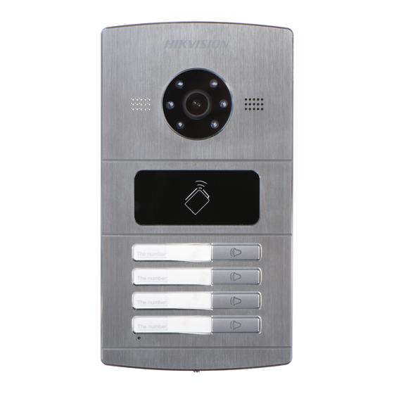
For device DS-KV8X02- IM, the number of calling buttons varies according to its model. Take the figure of device DS-KV8402-IM as an example. For device DS-KV8102-IM, there is only 1 calling button. For device DS-KV8202-IM, there are 2 calling buttons. -
Page 12: Appearance Of Ds-Kv8102-Xp
Video Intercom Door Station·User Manual Models Description Microphone Tamper Button You need not customize the Room No. for device DS-KV8102-IM. 2.2 Appearance of DS-KV8102-XP Figure 2-2 Appearance of DS-KV8102-XP Table 2-2 Description of DS-KV8102-XP Models Description Microphone Low Illumination Supplement... -
Page 13: Typical Application
One Resident Figure 3-1 Typical Application DS-KV8102-IM door station can also work as doorphone both in a villa or an apartment. Please refer to the typical application (2) and the typical application (3) in 3.2. 3.2 Typical Application of DS-KV8102-XP Please refer to the following figures for typical applications of DS-KV8102-IP/ DS-KV8102-VP door station. - Page 14 Video Intercom Door Station·User Manual DS-KV8102-IP/ DS-KV8102-VP door station can also work as doorphone both in a villa or an apartment. Please refer to the typical application (2) and the typical application (3). Client Software Indoor Station Indoor Indoor Extension 1 Video/Audio Extension 2 Center Master Station...
- Page 15 Video Intercom Door Station·User Manual In typical applicatin (2), DS-KV8102-IP/ DS-KV8102-VP door station and DS-KV8102-IM door station work as doorphone in a villa. Building Client Software Indoor Indoor Extension 1 Extension 2 Video/Audio Distributor Resident 2 Resident 1 Center Master Station...
-
Page 16: Terminals And Interfaces Of Wiring
Video Intercom Door Station·User Manual 4 Terminals and Interfaces of Wiring Please refer to the following figure for terminals and interfaces of door station. ①-⑤ ⑥-⑦ ⑧-⑨ ⑬ ⑩-⑫ Figure 4-1 Terminals and Interfaces Table 4-1 Descriptions of Terminals and Interfaces Terminals and Interfaces Name Color... -
Page 17: Installation And Wiring
To install the door station onto the wall, you are required to utilize a matched gang box. 5.1.1 Gang Box for DS-KV8X02-IM Please refer to the following figures for the dimensions of gang box for DS-KV8102-IM/ DS-KV8202-IM/ DS-KV8402-IM door station. -
Page 18: Wall Mounting With Gang Box Of Ds-Kv8X02-Im
Video Intercom Door Station·User Manual 5.1.2 Wall Mounting with Gang Box of DS-KV8X02-IM Steps: 1. Take the gang box and screws from the packing box. 2. Chisel a hole in the wall for inserting the gang box. The size of the hole should be 90 (width) ×170 (length) ×... -
Page 19: Installation Of Ds-Kv8102-Xp
Video Intercom Door Station·User Manual M4 Screw Figure 5-4 Secure the Door Station (DS-KV8X02-IM) 5.2 Installation of DS-KV8102-XP 5.2.1 Installation Plate for DS-KV8102-XP To install the DS-KV8102-XP model onto the wall, an installation plate and a gang box are required. Hollow Area 41.48 72.7... -
Page 20: Wall Mounting With Gang Box Of Ds-Kv8102-Xp
Video Intercom Door Station·User Manual The dimension of gang box for model DS-KV8102-IP/ DS-KV8102-VP door station is: 75 (width) × 75 (length) × 50 (depth) mm. The dimensions above are theoretical. The actual size can be slightly different from the theoretical dimension. - Page 21 Video Intercom Door Station·User Manual 6. After installing the installation plate, install the door station by inserting the rear component into the hollow area of the installation plate. While inserting the door station into the installation plate, incline the device by 5~10°, as shown in the figure below.
-
Page 22: Wiring Description
Video Intercom Door Station·User Manual 5.3 Wiring Description 5.3.1 Door Lock Wiring Figure 5-10 Door Lock Wiring Terminal DR_NC/DR_COM is set as default for connecting magnetic lock/electric bolt; terminal DR_NO/DR_COM is set as default for connecting electric strike. To connect electric lock, it is required to set the output of terminal DR_NC/DR_COM/DR_NO to be electric lock with Batch Configuration Tool or iVMS-4200 client software. -
Page 23: Door Magnetic Wiring
Video Intercom Door Station·User Manual 5.3.2 Door Magnetic Wiring Figure 5-11 Door Magnetic Wiring To connect door magnetic, it is required to set the input of one alarm in terminal (ALARM_1, ALARM_2, ALARM_3, or ALARM_4) to be door magnetic with Batch Configuration Tool or iVMS-4200 client software. -
Page 24: Alarm Device Input Wiring
Video Intercom Door Station·User Manual To connect exit button, it is required to set the input of one alarm in terminal (ALARM_1, ALARM_2, ALARM_3, or ALARM_4) to be exit button with Batch Configuration Tool or iVMS-4200 client software. 5.3.4 Alarm Device Input Wiring Figure 5-13 Alarm Device Input Wiring To connect other alarm devices, it is required to set the input of one alarm in terminal (ALARM_1, ALARM_2, ALARM_3, or ALARM_4) to be custom with Batch Configuration... -
Page 25: Before You Start
Video Intercom Door Station·User Manual 6 Before You Start For the first time use of the device, you are required to activate the device. You can activate the device and set the device password via internet with Batch Configuration Tool, or with iVMS-4200 client software, or with Video Intercom Set-up Tool. To activate the device with Video Intercom Device Set-up Tool, refer to Chapter 7. -
Page 26: Video Intercom Device Set-Up Tool
Video Intercom Door Station·User Manual 7 Video Intercom Device Set-up Tool Purpose: You can assign the device to the community, active and set the device by using the video intercom device set-up tool. 7.1 Setting a Community Structure Purpose: You can set a community structure, based on the real community situation, on the video intercom device set-up tool, and then assign devices to the community accordingly. -
Page 27: Setting Community
Video Intercom Door Station·User Manual Figure 7-2 Project Settings 3. Click the Apply button to enable the settings. The default amount of project is 1 if the amount is not set in the textbox. 7.1.2 Setting Community Steps: 1. Check the checkbox of a certain project from the community structure. 2. -
Page 28: Setting Building
Video Intercom Door Station·User Manual If you check the checkbox of All, then all projects in the community structure will be selected, and will be added the same amount of community. 7.1.3 Setting Building Steps: 1. Check the checkbox of a certain community from the community structure. 2. -
Page 29: Setting Room
Video Intercom Door Station·User Manual Figure 7-5 Floor Settings 3. Click the Apply button to enable the settings. If you check the checkbox of All, then all buildings in the community structure will be added the same amount of floor. ... -
Page 30: Activating And Setting Main Door Station
Video Intercom Door Station·User Manual 3. Click the Apply button to enable the settings. If you check the checkbox of All, then all floors in the community structure will be selected, and will be added the same amount of room. ... -
Page 31: Activating And Setting Sub Door Station
Video Intercom Door Station·User Manual 4. Set the main door station floor No.. 5. Enter the SIP IP address, master station IP address, center IP address, center port No., subnet mask, and gateway address. 6. Click the Refresh button to view the online indoor station of the same segment. 7. - Page 32 Video Intercom Door Station·User Manual You can activate the online sub door station, and configure the number of online sub door station. Before You Start: Press the Sub Door Station tab to switch to the sub door station settings. Steps: 1.
- Page 33 Video Intercom Door Station·User Manual Figure 7-10 Sub Door Station Settings Interface The default sub door station floor No. is 1. The sub door station amount should be no higher than 8. You can select one project or multiple projects; one community or multiple communities;...
-
Page 34: Batch Configuration Tool
Video Intercom Door Station·User Manual 8 Batch Configuration Tool 8.1 Activating Device Remotely Purpose: The device cannot be operated until it is activated. You can remotely activate the device via Batch Configuration Tool or via iVMS-4200 client. Here take the Batch Configuration Tool as example, and for further information, please refer to the user manual in the disk. -
Page 35: Editing Network Parameters
Video Intercom Door Station·User Manual When the device is not activated, the basic operation and remote operation of device cannot be performed. 8.2 Editing Network Parameters Purpose: You can edit the network parameters of online devices. Steps: 1. Select an online device in the online devices list in the lower part of the batch configuration software interface. -
Page 36: Adding Device
Video Intercom Door Station·User Manual 8.3 Adding Device The software provides 3 ways for adding the door station (V series). You can add the active online devices within your subnet, add devices by IP address, and add devices by IP segment. 8.3.1 Adding Online Devices Steps: 1. -
Page 37: Adding By Ip Address Or Ip Segment
Video Intercom Door Station·User Manual Figure 8-6 Login Dialog Box 4. Enter the user name and password. 5. Click the OK button to save the settings. Only the devices that are successfully logged in will be added to the device list for configuration. -
Page 38: Remote Configuration
Video Intercom Door Station·User Manual Adding by IP Segment Purpose: You can add many devices at once whose IP addresses are among the IP segment. Steps: 1. Select IP Segment in the adding mode drop-down list. 2. Set the Start IP Address and End IP Address. 3. - Page 39 Video Intercom Door Station·User Manual Device Information Click the Device Information button to enter device basic information interface. You can view basic information (the device type, and serial No.), and version information of the device. Figure 8-11 Device Information Interface General Click the General button to enter device general parameters settings interface.
- Page 40 Video Intercom Door Station·User Manual Check the checkbox of Enable NTP to enable NTP. Enter the server address, NTP port, and synchronization interval. 3. Click the Apply button to save and realize the time settings. The default Port No. is 123. System Maintenance Purpose: You can operate the system management and remote upgrading on the system...
- Page 41 Video Intercom Door Station·User Manual Figure 8-15 Reboot Click the Yes button to reboot the system. • Restore Default Settings Click the Restore Default Settings button to pop up the restore default settings dialog box. Figure 8-16 Restore Default Settings Click the Yes button to restore the default parameters.
- Page 42 Video Intercom Door Station·User Manual Figure 8-18 Import Configuration File Window Select the path of remote configuration files. Click the Open button to import the remote configuration file and pop up a reboot information dialogue box. Figure 8-19 Reboot Information •...
- Page 43 Video Intercom Door Station·User Manual Click the Save button to export the configuration file, and pop up an information box for exporting. Figure 8-21 Information Box for Exporting Remote Upgrade • Reboot Click the button to pop up the window for opening upgrade file. Figure 8-22 Window for Opening Upgrade File Select the upgrade file, and click the Open button.
- Page 44 Video Intercom Door Station·User Manual Figure 8-24 User Information Editing Interface 2. Select the user to edit and click the Modify button to enter the user parameter interface. Figure 8-25 User Parameter Interface 3. Enter the new password, and confirm it. 4.
-
Page 45: Video Intercom
Video Intercom Door Station·User Manual Figure 8-26 RS485 Parameters RS485 configuration is reserved in this version. 8.4.2 Video Intercom Device Number Configuration Steps: 1. Click the Device Information button to enter device number configuration interface. Door Station Select door station from the drop-down list of the device type Figure 8-27 Device Number Configuration (V Series Door Station) Enter the project No., community No., building No., floor No., and serial No. - Page 46 For doorphone, the serial No. is not necessary to be configured. Please use the doorphone along with the main door station (V series or D series). The models DS-KV8102-IP, DS-KV8102-VP and DS-KV8102-IM are supported for using as doorphone and door station (V Series). The models DS-KV8202-IM, DS-KV8402-IM are supported for using only as door station (V Series).
- Page 47 Video Intercom Door Station·User Manual Access Control and Elevator 1. Click the Access Control and Elevator button to enter password changing interface. Figure 8-30 Access Control and Elevator Settings Interface 2. Set corresponding parameters on the access control and elevator settings interface. ...
- Page 48 Video Intercom Door Station·User Manual Figure 8-31 I/O Input and Output Interface 2. Select I/O input No., input mode, I/O output No., and output mode. 3. Click the Apply button to enable the settings. There are 4 I/O Input Terminals, Terminal 1~4 correspond to ALARM_1~ALARM_4 interfaces of door station.
-
Page 49: Network
2. Select the button number. 3. Enter the floor No. and the room No.. 4. Click the Apply button to enable the settings. For DS-KV8102-IM, DS-KV8102-IP, and DS-KV8102-VP, there is no need setting the Room No.. 8.4.3 Network Local Network Configuration Steps: 1. - Page 50 Video Intercom Door Station·User Manual Linked Devices Network Configuration Purpose: On the linked devices network configuration interface, you can configure the network parameters of master stations, SIP servers and management centers of the same LAN. Steps: 1. Click the Linked Device Network Configuration button to enter the devices network configuration interface.
-
Page 51: Video Display
Video Intercom Door Station·User Manual Figure 8-36 FTP Parameters Interface 2. Check the checkbox of Enable Main FTP. 3. Select IP address from the drop-down list of server mode. 4. Enter the FTP server address, and port No.. 5. Check the checkbox to enable the anonymity (optional). 6. - Page 52 Video Intercom Door Station·User Manual Figure 8-37 Video Parameters Interface 2. Select the channel No. 3. Select the resolution, frame rate, and video format. 4. Select to enable/disable WDR. 5. Set the WDR level. 6. Set the brightness, hue, contrast, saturation, and sharpness of the video. 7.
-
Page 53: Setting The Door Station Via Ivms-4200
Video Intercom Door Station·User Manual 9 Setting the Door Station via iVMS-4200 9.1 System Configuration After running the iVMS-4200, enter Control Panel -> Maintenance and Management -> System Configuration -> Video Intercom to configure the video intercom parameters accordingly. You can configure the ringtone, Max. ring duration, Max. speaking time with indoor station and Max. -
Page 54: Live View Of Device
Video Intercom Door Station·User Manual 9.3 Live View of Device Steps: 1. Enter the main view interface of iVMS-4200 client software to display the live view of door station (V Series). Figure 9-2 Live View of Door Station (V Series) 2. -
Page 55: Picture Storage On Storage Server
Video Intercom Door Station·User Manual 9.4 Picture Storage on Storage Server 9.4.1 Adding Storage Server Purpose: When the device is under armed status, it will capture the picture automatically after unlocking the door. The captured picture can be uploaded and stored in the storage server. -
Page 56: Formatting The Hdds
Video Intercom Door Station·User Manual Figure 9-5 Storage Sever Interface You can add the storage server by referring to Section 8.3 Adding Device. This function does not apply to the doorphone. 9.4.2 Formatting the HDDs The HDDs of the storage server need to be formatted for the captured picture storage. Steps: 1. -
Page 57: Configuring Storage Server Picture Storage
Video Intercom Door Station·User Manual Figure 9-6 Remote Configuration Interface of Storage Server Formatting the HDDs is to pre-allocate the disk space for storage and the original data of the formatted HDDs will not be deleted. 9.4.3 Configuring Storage Server Picture Storage Before you start: The storage server needs to be added to the client software and the HDDs need to be formatted for the captured pictures storage. -
Page 58: Group Management
Video Intercom Door Station·User Manual Figure 9-7 Record Schedule Settings 5. Click Set Quota to enter the HDD management interface of the storage server. You can set the corresponding quota ratio for captured picture information. Figure 9-8 Storage Settings Example: If you set the picture quota as 60%, then the 60% of the storage space can be used for storing the captured pictures. -
Page 59: Adding Group
Video Intercom Door Station·User Manual You can add groups to community, outer door station, or other, and assign devices to each group. 9.5.1 Adding Group 1. Click the Group Management tab to enter the group management interface. Figure 9-9 Group Management Interface 2. -
Page 60: Assigning Device To Group
Video Intercom Door Station·User Manual Figure 9-11 Group Adding Interface (Outer Door Station) 1) Check the checkbox of outer door station. 2) Enter the project No.. Selecting Other as Group Type Figure 9-12 Group Adding Interface (Other) 1) Check the checkbox of other. 2) Enter the name. -
Page 61: Modifying Device Information
Video Intercom Door Station·User Manual Figure 9-13 Resident Adding Interface 2. Check the checkbox of device and enter the Room No. of indoor stations to assign the device to the community. 3. Click the OK button to save the settings. 9.5.3 Modifying Device Information 1. -
Page 62: Card Management
Video Intercom Door Station·User Manual Figure 9-15 Group Deleting Interface 3. Click the OK button to complete the group deleting operation. 9.6 Card Management Purpose: You can add unauthorized cards to the community and then you can assign the cards to the corresponding indoor station and outdoor stations. - Page 63 Video Intercom Door Station·User Manual 3. Select card type: Resident Card, Other Card. 4. Enter Start Card No. and End Card No. (adding in batch), or enter card No. (adding by single or card reader). Figure 9-17 Adding in Batch Figure 9-18 Adding by Single or Card Reader 5.
- Page 64 Video Intercom Door Station·User Manual 2. Issue Resident Card or Other Card. Issuing Resident Card 1) Select Community on the left and the indoor stations of the community will be listed in the resident list. Figure 9-20 Resident Card Issuing Interface Click the button to pop up card selection interface for selecting unauthorized cards to be issued to the indoor station.
- Page 65 Video Intercom Door Station·User Manual 1) Select Other on the left group list and the name for other card issuing will be listed in the right list. Figure 9-22 Other Card Issuing Interface Click the button to pop up card selection interface for selecting unauthorized cards to be issued to the indoor station.
- Page 66 Video Intercom Door Station·User Manual Deleting Card Deleting Unauthorized Card 1) On the card management interface (Figure 8-11), check the checkbox(ex) of unauthorized card(s). 2) Click the Delete Card button to pop up unauthorized card deleting box. Figure 9-24 Card Deleting Information Box 3) Click the OK button to delete the card(s).
- Page 67 Video Intercom Door Station·User Manual Figure 9-25 Bath Import Interface 2. Click the Export Template button to export the template of the batch import file. Figure 9-26 Template File Exporting Interface 3. Fill in the template of the batch import file and click the Save button to save it. 4.
-
Page 68: Normal Card Management
Video Intercom Door Station·User Manual 5. Click the Open button. 6. Click the OK button to start importing the batch import file. Exporting Unauthorized Cards in Batch 1. Click the Batch Export button after adding unauthorized cards. Figure 9-28 Batch Export Interface 2. -
Page 69: Notice Management
Video Intercom Door Station·User Manual To issue cards with card issuer, please connect the card reader DS-K1F100-D8 (purchased separately) to PC via USB interface. Open iVMS-4200 and enter the directory of Video Intercom->Card Management->Unauthorized Card->Add Card. Swipe the unauthorized card in turn and the card No. will be read and added to the device automatically. - Page 70 Video Intercom Door Station·User Manual Figure 9-31 Tool Menu 2. Set the arming status of the device as armed, and the alarm information will be auto uploaded to the client software when alarm occurs Figure 9-32 Device Arming Control Figure 9-33 Alarm Events After adding the device to the client software, it will be armed automatically.
-
Page 71: Local Operation
Take the figure of device DS-KV8402-IM as an example. For device DS-KV8102-IM, there is only 1 calling button. For device DS-KV8202-IM, there are 2 calling buttons. For device DS-KV8402-IM, there are 4 calling buttons. -
Page 72: Calling Resident (Ds-Kv8102-Xp)
Video Intercom Door Station·User Manual When live view of door station is displayed on other devices or door station is calling resident, the door station will detect the brightness of video. When the brightness is lower than the expected threshold, the supplement light will be enabled. ... -
Page 73: Issuing Card
Video Intercom Door Station·User Manual When the supplement light is enabled, the backlight of key will be auto-enabled, otherwise, the door station will detect the brightness of live view and enable the backlight of key when the brightness of live view is lower than expected threshold. 10.2 Issuing Card Purpose: You can assign the card to the door station or doorphone by issuing cards. - Page 74 Video Intercom Door Station·User Manual You cannot unlock the door by swiping the main card.
-
Page 75: Appendix
Door Lock Wiring (With Door Magnetic) RVV 4*1.0 Door Lock Wiring (Without Door Magnetic) RVV 2*1.0 Exit Button Wiring RVV 2*0.5 Specification of DS-KV8X02-IM Model DS-KV8102-IM DS-KV8202-IM DS-KV8402-IM Parameters System Parameters Processor High-Performance Embedded SOC Processor Operation System Embedded Linux Operation System... - Page 76 Video Intercom Door Station·User Manual Model DS-KV8102-IM DS-KV8202-IM DS-KV8402-IM Parameters 25 fps Video Frame Audio Parameters Audio Input Built-in Omnidirectional Microphone Audio Output Built-in Loudspeaker Audio Compression G.711U Standard Audio Compression 64 Kbps Rate Audio Quality Noise Suppression and Echo Cancellation...
-
Page 77: Specification Of Ds-Kv8102-Xp
Video Intercom Door Station·User Manual Model DS-KV8102-IM DS-KV8202-IM DS-KV8402-IM Parameters Other Parameters Indoor Station Access Amount Material Aluminum Alloy DC 24V, Power Over Network Cable (DS-KAD606, DS-KAD612) Power Supply DC 12V Consumption ≤12 W Working - 40° C to + 70°C (-40° F to 158° F) - Page 78 Video Intercom Door Station·User Manual Model DS-KV8102-IP DS-KV8102-VP Parameters Audio Input Built-in Omnidirectional Microphone Audio Output Built-in Loudspeaker Audio Compression G.711 U Standard Audio Compression 64 Kbps Rate Audio Quality Noise Suppression and Echo Cancellation Access Control Parameters Internal Card Built-in IC Card Reader Reader Exit Button...
- Page 79 Video Intercom Door Station·User Manual Model DS-KV8102-IP DS-KV8102-VP Parameters DC 24V, Power Over Network Cable (DS-KAD606, DS-KAD612) Power Supply DC 12V Consumption ≤12 W Working -40° C to +70° C (-40° F to 158° F) Temperature Working Humidity 10% to 90% IP Protection Level IP65 Dimension...
- Page 80 Video Intercom Door Station·User Manual...
Need help?
Do you have a question about the DS-KV8102-IM and is the answer not in the manual?
Questions and answers