
Related Manuals for PCI MicroTrans EQ


Summary of Contents for PCI MicroTrans EQ
- Page 1 MicroTrans Signal Processor Operation & Maintenance Manual Engineered for accuracy, applicability, durability and simplicity in HVAC air systems and industrial process control loops...
-
Page 3: Table Of Contents
MicroTrans Operation & Maintenance Manual TABLE OF CONTENTS TABLE OF CONTENTS ..........................i INTRODUCTION ..........................1 1.1. DESCRIPTION ..........................1 1.2. BASIC OPERATION ........................1 1.3. SPECIFICATIONS ........................1 1.3.1. Power Supply ........................1 ... - Page 4 MicroTrans Operation & Maintenance Manual 8.4.2. Lockdown Delay ......................... 19 8.5. FLOW CORRECTION ......................19 8.5.1. Flow Correction (K-Factor) ....................19 8.5.2. Flow Correction (K-Factor Calculator) ................19 8.6. AUTOZERO ..........................20 ...
-
Page 5: Introduction
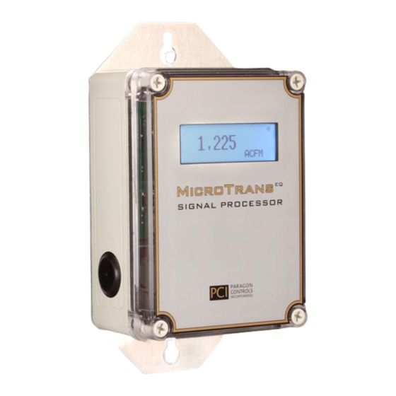
MicroTrans Operation & Maintenance Manual 1. INTRODUCTION 1.1. DESCRIPTION The MicroTrans Signal Processor employs current state-of-the-art digital microprocessor technology to produce highly stable and accurate differential pressure and air flow measurements. The MicroTrans is factory configured and calibrated to the exact specification determined at time of order. Simple field configuration of engineering units, operating range, process noise filtering, alarm set points, etc., are performed via password protected intuitive menus that are accessed through the integral six button touch pad. -
Page 6: High/Low Alarm Relay Outputs
MicroTrans Operation & Maintenance Manual 1.3.6. High/Low Alarm Relay Outputs Two single (1 form C) dry contacts rated for: 5 amps at 30VAC/DC 10 amps at 120VAC 1.4. SAFETY 1.4.1. Electrical Connections Before any electrical connections are made, ensure the POWER SWITCH is in the OFF position. 1.4.2. -
Page 7: Product Dimensions
MicroTrans Operation & Maintenance Manual 2. PRODUCT DIMENSIONS 2.1. NEMA 1 MECHANICAL DIMENSIONS 4.625" 3.500" I.D./DATA LABEL 75 F 1,225 ACFM MicroTrans SIGNAL PROCESSOR 8.250" 7.625" PARAGON CONTROLS INCORPORATED 1.4" 0.20" DIA (TYP OF 4) PG21(3/4") 2.265" 1.2" PG13.5(1/2") - TYP OF 3 Paragon Controls Incorporated Revision Level 012... -
Page 8: Nema 4 Mechanical Dimensions
MicroTrans Operation & Maintenance Manual 2.2. NEMA 4 MECHANICAL DIMENSIONS MOUNTING SCREW DIA. UP TO 1/4". (TYP OF 2) I.D./DATA LABEL 75 F 1,225 ACFM 7.0" MicroTrans 8.2" 9.56" SIGNAL PROCESSOR PARAGON CONTROLS INCORPORATED PG13.5(1/2") PG13.5(1/2") 5.0" STANDARD 1/4" COMPRESSION OPTION PG21(3/4") 3.12"... -
Page 9: Installation
MicroTrans Operation & Maintenance Manual 3. INSTALLATION 3.1. ELECTRICAL & PNEUMATIC INSTALLATION NEMA 1 & 4 Option - Remove the cover by turning each corner cover mounting screw counter clockwise. Both NEMA 1 & NEMA 4 enclosures incorporate three 1/2 inch conduit connections and one 3/4 inch conduit connection to interface all electrical wiring and pneumatic tubing to the device. -
Page 10: Temperature Transmitter Connection
MicroTrans Operation & Maintenance Manual 3.2. TEMPERATURE TRANSMITTER CONNECTION Shielded cable is recommended for all connections between the MicroTrans and the Temperature Transmitter. 3.2.1. 4-20mA Output/2-Wire Loop Powered Temperature Transmitter POWER SWITCH ENTER S2 S4 TEMP. PROC. INPUT OUTPUT J3 (ALARM OPTION) S1 SET TO mA POSITION 1 2 3... -
Page 11: 0-10Vdc Output/24Vdc Power 3-Wire Temperature Transmitter
MicroTrans Operation & Maintenance Manual 3.2.3. 0-10VDC Output/24VDC Power 3-Wire Temperature Transmitter POWER SWITCH ENTER S2 S4 TEMP. PROC. INPUT OUTPUT J3 (ALARM OPTION) S1 SET TO V POSITION 1 2 3 4 5 6 7 8 11 12 13 14 15 16 17 18 + 24VDC OUTPUT POWER + TEMPERATURE INPUT - TEMPERATURE INPUT(GND) -
Page 12: Input/Output Set-Up
MicroTrans Operation & Maintenance Manual 4. INPUT/OUTPUT SET-UP The MicroTrans has been configured and calibrated at the factory for the specific application. Refer to the MicroTrans Set-Up label located on the left side of unit to verify correct Input/Output configuration for the application. If input or output configuration changes are required refer to the tables in the sections below and the figure in Section 3.1. -
Page 13: Common Startup Configuration Changes
MicroTrans Operation & Maintenance Manual 5. COMMON STARTUP CONFIGURATION CHANGES 5.1. AREA FACTOR The Area Factor can be entered or modified as follows: Step 1. From the active display, enter the Tech. Configuration Menu by pressing the Up/Down keys simultaneously. Step 2. -
Page 14: Operating Range
MicroTrans Operation & Maintenance Manual -Area Factor Example- Op Range value within Area Factor New Min/Max values (FT ) Accepted (001.200) Area Factor (FT ) (001.000) Warning Message Entering a new Area Factor and pressing Op Range Outside Operating Range the Enter button will Allowable Value. -
Page 15: Temperature Compensation For Air Density
MicroTrans Operation & Maintenance Manual 5.3. TEMPERATURE COMPENSATION FOR AIR DENSITY The Temperature Compensation option compensates the flow and velocity signal for density changes caused by variations in the process air temperature. The following menus for configuration of Temperature Compensation are only available if the Temperature Compensation option is purchased. Additionally, an input signal from an external temperature transmitter or the building automation system is required;... - Page 16 MicroTrans Operation & Maintenance Manual If the new temperature values cause the existing Operating Range Value to be outside the new calculated Minimum or Maximum Full Scale Value, the below Warning Message will appear and the Operating Range will be reset to the new Maximum Full Scale Value by pressing Enter. The display will automatically jump to the Op Range Menu allowing the user to enter a new Operating Range Value.
-
Page 17: Temperature Input
MicroTrans Operation & Maintenance Manual 5.3.4. Temperature Input The Temperature Input Menu allows the user to select between three temperature input options (Fixed, Variable, and Net) for the flow calculations. If Fixed is selected the default temperature value entered in the Fixed Value Menu (see Section 5.3.5) is used. -
Page 18: Active Displays & Key Functions
MicroTrans Operation & Maintenance Manual 6. ACTIVE DISPLAYS & KEY FUNCTIONS 6.1. POWER-UP INITIATION DISPLAY Upon initial power-up, Software Revision information will be displayed on the graphic display for approximately 5 seconds. EQ-1 Software Rev. XX.XXX Module Rev. XX.XXX 6.2. PROCESS DISPLAY DESCRIPTIONS After power-up initialization, the following information will appear on the graphic display depending upon the options purchased. -
Page 19: Key Functions
MicroTrans Operation & Maintenance Manual 6.3. KEY FUNCTIONS The following figure and description identify the function of each Key. POWER SWITCH ENTER TEMP. PROC. INPUT OUTPUT J3 (ALARM OPTION) 1 2 3 4 5 6 7 8 11 12 13 14 15 16 17 18 Number Description Enter Key - Allows a user to enter into the Field Menu, enter into a selected menu item, or... -
Page 20: Display Menus
MicroTrans Operation & Maintenance Manual 7. DISPLAY MENUS 7.1. FIELD SETUP & TECH. CONFIGURATION MENUS The following table shows the Field Setup and Tech. Configuration Menus for devices set to monitor Flow, Velocity, and Pressure. The display will vary depending upon the options purchased. MicroTrans Setup for Flow or Velocity Field Setup Menu... -
Page 21: Field Setup Menus
MicroTrans Operation & Maintenance Manual 8. FIELD SETUP MENUS To set parameters under the Field Setup Menus refer to the following procedure, below subsections, and Section 6.3 for Key functions. Step 1. Enter the Field Setup Menu by depressing and holding the Enter Key for 5 seconds. -
Page 22: Engineering Units
MicroTrans Operation & Maintenance Manual 8.3. ENGINEERING UNITS A list of engineering units are available for the user to select from for display purposes to meet customer requirements. Changing the engineering units will affect the process display and the alarm value menus. Field Setup Menu ... -
Page 23: Lockdown Delay
MicroTrans Operation & Maintenance Manual 8.4.2. Lockdown Delay The Lockdown Delay Menu allows the user to enter a lockdown time delay (0-20 seconds) that will delay the display and output lockdown from occurring until the flow value or output value has remained below the lockdown value for that duration. -
Page 24: Autozero
MicroTrans Operation & Maintenance Manual -FLOW CORRECTION EXAMPLE- The balancer is consistently measuring a value of 9,500 CFM, which is 500 CFM less than the 10,000 CFM value on the MicroTrans display. The user would then perform the following math function: Measured Value / Displayed Value = K-Factor so 9,500 CFM / 10,000 CFM = 0.950. -
Page 25: Autozero Test Interval
MicroTrans Operation & Maintenance Manual 8.6.3. AutoZero Test Interval For troubleshooting or testing the AutoZero function, the AutoZero Test Interval Menu allows the user to select an Auto Zero test frequency of once a minute to once every 30 minutes in 1 minute increments. Use the UP/DOWN keys to select the interval value. -
Page 26: Temperature Values
MicroTrans Operation & Maintenance Manual 8.7.2. Temperature Values The Temperature Values Menu allows the factory or user to set the minimum and maximum temperature range values that represent the input signal from the external temperature transmitter or the building automation system. Field Setup Menu ... -
Page 27: Temperature Input
MicroTrans Operation & Maintenance Manual 8.7.3. Temperature Input The Temperature Input Menu allows the user to select between three temperature input options (Fixed, Variable, and Net) for the flow calculations. If Fixed is selected the default temperature value entered in the Fixed Value Menu (see Section 5.3.5) is used. -
Page 28: Process Output Filter
MicroTrans Operation & Maintenance Manual 8.9. PROCESS OUTPUT FILTER The Process Output Filter Menu allows the user to adjust the Process Output Filters rolling average algorithm by setting the Sample Interval Time value in seconds and the number of rolling average Sample Counts. -
Page 29: Alarm Values
MicroTrans Operation & Maintenance Manual 8.10.2. Alarm Values The Alarm Value Menu allows the user to enter the Low or the High flow or pressure alarm value. Alarm values will be displayed in the same engineering units selected in the Eng. Units Menu (see Section 8.3). -
Page 30: Factory Defaults
MicroTrans Operation & Maintenance Manual 8.12. FACTORY DEFAULTS If pressure calibration changes have been made incorrectly to the MicroTrans program, all pressure calibration values and device settings can be restored to the original factory settings by selecting YES and pressing Enter in both the Set To Factory Defaults Menu and the Verify Set To Factory Defaults Menu (See Factory Defaults table below for a list of Saved Settings). -
Page 31: Tech Configuration Menus
MicroTrans Operation & Maintenance Manual 9. TECH CONFIGURATION MENUS To set parameters under the Tech Configuration Menu, refer to the procedure below, associated subsections and Section 6.3 for Key functions. Step 1. Enter the Tech Configuration Menu by pressing and holding the Up/Down Keys simultaneously for 5 seconds. -
Page 32: Minimum Calibration
MicroTrans Operation & Maintenance Manual -Area Factor Example- Op Range value within Area Factor New Min/Max values (FT ) Accepted (001.200) Area Factor (FT ) (001.000) Warning Message Entering a new Area Factor and pressing Op Range Outside Operating Range the Enter button will Allowable Value. -
Page 33: 50% Calibration
MicroTrans Operation & Maintenance Manual 9.3. 50% CALIBRATION The 50% Calibration Menu is only available when the MicroTrans is configured by Paragon at the time of order for pressure; it allows a user to perform a 50% transducer calibration to eliminate zero drift in a bipolar transducer. -
Page 34: Altitude
MicroTrans Operation & Maintenance Manual 9.6. ALTITUDE The Altitude Menu allows user to enter the specific altitude for the job other than the standard value of 0 feet above mean sea level for the density calculations. Tech. Config. Password: 1000 ... -
Page 35: Process Output Calibration
MicroTrans Operation & Maintenance Manual 9.7. PROCESS OUTPUT CALIBRATION 9.7.1. Minimum Calibration The Minimum Calibration Menu allows the user to make output zero adjustments. Monitor the output and with each Up or Down key depression, the output will increase or decrease by 0.01VDC or 0.01mA depending on output selection. -
Page 36: Probe Coefficient
MicroTrans Operation & Maintenance Manual 9.8.1. Probe Coefficient The Probe Coefficient Menu allows the user to modify the formula constant of 1096.70 for a non- amplified Pitot-type flow sensor. Tech. Config. Password: 1000 Temp. Fixed Value Correction Coeff. Altitude Probe Output Calibration (1096.70) -
Page 37: Four Point Flow Correction
MicroTrans Operation & Maintenance Manual Since is known for a given job site, some sensor and air handling unit manufacturers will include this value (or the value for standard air density 0.075 lbm/ft ) in the factor F supplied, simplifying the above equation to: √∆... -
Page 38: Mac Address (Bacnet Communication Option)
MicroTrans Operation & Maintenance Manual 9.10. MAC ADDRESS (BACNET COMMUNICATION OPTION) When the BACnet Communication option is ordered, the MAC Address Menu allows the user to set a unique device address when connecting to a BACnet network. The default is 02. For additional information refer to the Communication O&M. -
Page 39: Baud Rate (Bacnet & Modbus Communication Options)
MicroTrans Operation & Maintenance Manual 9.13. BAUD RATE (BACNET & MODBUS COMMUNICATION OPTIONS) The Baud Rate Menu allows the user to set a unique network baud rate. The current BACnet protocol supports 9.6, 19.2, 38.4 and 76.8 Kbps baud rate. Modbus communications supports 9.6, 19.2, 38.4, 57.6 and 115.2 Kbps baud rate. -
Page 40: Warning Messages
MicroTrans Operation & Maintenance Manual 10. WARNING MESSAGES 10.1. INPUT PRESSURE OVERRANGE MESSAGE If the input pressure exceeds the entered Operating Range Value, the following message will appear on the display. It will alternate between the process display and the error message until the input falls below the Operating Range Value. -
Page 41: Troubleshooting Guide
MicroTrans Operation & Maintenance Manual 11. TROUBLESHOOTING GUIDE TROUBLESHOOTING TABLE SYMPTOM SOLUTION No Display or Back Light Verify ON/OFF switch is in ON position Verify correct input power and connection at 3 pin connector J1 Contact Factory Display background is too dark or Adjust RP1 Display potentiometer located in the characters are too light. - Page 42 MicroTrans Operation & Maintenance Manual TROUBLESHOOTING TABLE SYMPTOM SOLUTION Continued If the Temperature Compensation Option is installed, verify correct temperature input signal. Verify that the temperature input is connected correctly. Contact Factory Incorrect Temperature Reading Verify Temperature Transmitter specifications match with MicroTrans ID Label (Current/Voltage, Temperature Range) Verify Temperature Transmitter is connected...
- Page 43 MicroTrans Operation & Maintenance Manual TROUBLESHOOTING TABLE SYMPTOM SOLUTION 11. Continued Check for a pinched tube beneath the main board. (Caution: Remove power before removing board) Contact Factory Paragon Controls Incorporated Revision Level 012...
- Page 44 Paragon Controls Incorporated P.O. Box 99, Forestville, CA 95436 http://www.paragoncontrols.com Phone 707 / 579-1424 Revision Level 012...
Need help?
Do you have a question about the MicroTrans EQ and is the answer not in the manual?
Questions and answers