
Subscribe to Our Youtube Channel
Related Manuals for PCI MicroTrans II


Summary of Contents for PCI MicroTrans II
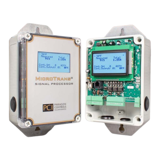
- Page 1 MicroTrans Summing Signal Processor Operation & Maintenance Manual Engineered for accuracy, applicability, durability and simplicity in HVAC air systems and industrial process control loops...
-
Page 3: Table Of Contents
MicroTrans Summing Operation & Maintenance Manual TABLE OF CONTENTS TABLE OF CONTENTS ..........................i INTRODUCTION ..........................1 1.1. DESCRIPTION ..........................1 1.2. BASIC OPERATION ........................1 1.3. PI1/D Control Loop ........................1 1.3.1. PI1/D Parameter Description and Response ................. 1 1.3.2. - Page 4 MicroTrans Summing Operation & Maintenance Manual 5.4.2. Temperature Units ......................14 5.4.3. Temperature Values ......................15 5.4.4. Temperature Input ....................... 16 5.4.5. Fixed Value ......................... 17 ACTIVE DISPLAYS & KEY FUNCTIONS ................... 18 6.1. POWER-UP INITIATION DISPLAY ..................18 6.2. PROCESS DISPLAY DESCRIPTIONS ...................
- Page 5 MicroTrans Summing Operation & Maintenance Manual 9.1.9. Economizer Override ......................38 9.2. AREA FACTOR ........................38 9.3. TRANSDUCER CALIBRATION ..................... 40 9.3.1. Minimum Calibration ......................40 9.3.2. 50% Calibration ........................40 Span Calibration........................41 9.3.3. 9.4. TEMPERATURE FIXED VALUE (No Temp Comp Option) ..........41 9.5.
-
Page 7: Introduction
MicroTrans Summing Operation & Maintenance Manual 1. INTRODUCTION 1.1. DESCRIPTION The MicroTrans Summing Signal Processor employs current state-of-the-art digital microprocessor technology to produce highly stable and accurate air flow measurements. The MicroTrans is factory configured and calibrated to the exact specification determined at time of order. The MicroTrans Summing Signal Processor is capable of receiving an external air flow signal (4-20mA / 0-10 VDC) , summing the two air flow values and displaying the MicroTrans measured air flow and the total air... -
Page 8: Correctly Tuned Control Loop
MicroTrans Summing Operation & Maintenance Manual Inverse Derivative (1/D): The function of the 1/D parameter is to filter out the noise by delaying the controller response for a specific time period and then give a quick boost to the control output signal. The 1/D function helps improve response and stability of the control loop. -
Page 9: Pi1/D Control Loop
MicroTrans Summing Operation & Maintenance Manual 1.3.2.1. Poorly Tuned Control Loop A poorly tuned control loop may respond to an error change too quickly and overshoot the setpoint value, respond to slowly and never return to setpoint value or continually oscillate above and below the setpoint value (See Figure 2). -
Page 10: Specifications
MicroTrans Summing Operation & Maintenance Manual 1.4. SPECIFICATIONS 1.4.1. Power Supply 20 to 28 VAC/DC 1.4.2. Power Consumption Standard Unit: 192mA at 24VAC 113mA at 24VDC Full Options: 417mA at 24VAC 229mA at 24VDC 1.4.3. Accuracy ±0.25% full scale (Standard) ±0.10% full scale (Optional) 1.4.4. -
Page 11: Safety
MicroTrans Summing Operation & Maintenance Manual 1.5. SAFETY 1.5.1. Electrical Connections Before any electrical connections are made, ensure the POWER SWITCH is in the OFF position. 1.5.2. Static Electricity The circuit board contains components which are susceptible to damage caused by static electrical discharge. -
Page 12: Product Dimensions
MicroTrans Summing Operation & Maintenance Manual 2. PRODUCT DIMENSIONS 2.1. MECHANICAL DIMENSIONS MOUNTING SCREW DIA. UP TO 1/4". (TYP OF 2) I.D./DATA LABEL 75 F Measured Total 1,225 3,500 Cont. Sp: 1500 ACFM 7.0" Cont. Output: 45% 8.2" MicroTrans 9.56" SIGNAL PROCESSOR PARAGON CONTROLS... -
Page 13: Installation
MicroTrans Summing Operation & Maintenance Manual 3. INSTALLATION 3.1. ELECTRICAL & PNEUMATIC INSTALLATION Remove the cover by turning each corner cover mounting screw counter clockwise. The NEMA 4X enclosures incorporate three 1/2 inch conduit connections and one 3/4 inch conduit connection to interface all electrical wiring and pneumatic tubing to the device. Determine which conduit connection will be used and remove the black plug and install the appropriate conduit fitting (By Others). -
Page 14: Temperature Transmitter Connection
MicroTrans Summing Operation & Maintenance Manual 3.2. TEMPERATURE TRANSMITTER CONNECTION Verify Temperature Input switch (TMP) position matches the input signal type. Shielded cable is recommended for all connections between the MicroTrans and the Temperature Transmitter. 3.2.1. 4-20mA Output/2-Wire Loop Powered Temperature Transmitter LCD DISPLAY +PROCESS OUTPUT -PROCESS OUTPUT... -
Page 15: 0-10Vdc Output/24Vdc Power 3-Wire Temperature Transmitter
MicroTrans Summing Operation & Maintenance Manual 3.2.3. 0-10VDC Output/24VDC Power 3-Wire Temperature Transmitter LCD DISPLAY +PROCESS OUTPUT -PROCESS OUTPUT +24VDC OUTPUT POWER +TEMPERATURE INPUT ECO PRO -TEMPERATURE INPUT(GND) POWER SWITCH DISPLAY +TEMP. OUTPUT -TEMP. OUTPUT(GND) VERIFY CORRECT TEMP ENTER INPUT SWITCH POSITION UP = mA DOWN = V 1 2 3... -
Page 16: Input/Output Set-Up
MicroTrans Summing Operation & Maintenance Manual 4. INPUT/OUTPUT SET-UP The MicroTrans has been configured and calibrated at the factory for the specific application. Refer to the MicroTrans Set-Up label located on the left side of unit to verify correct Input/Output configuration for the application. -
Page 17: Controller Output
MicroTrans Summing Operation & Maintenance Manual 4.6. CONTROLLER OUTPUT To change the output configuration, set the CNT switch as follows: (Note: See section 4.7 for voltage level select) Process Output AOUT (CNT) Selection 4-20mA 0-10VDC 0-5VDC 4.7. OUTPUT VOLTAGE SELECTION To change the output configuration (0-10VDC or 0-5VDC), perform the following procedure: Step 1. -
Page 18: Common Startup Configuration Changes
MicroTrans Summing Operation & Maintenance Manual 5. COMMON STARTUP CONFIGURATION CHANGES 5.1. AREA FACTOR The Area Factor can be entered or modified as follows: Step 1. From the active display, enter the Tech. Configuration Menu by pressing the Up/Down buttons simultaneously. Step 2. -
Page 19: Operating Range
MicroTrans Summing Operation & Maintenance Manual -Area Factor Example- Op Range value within Area Factor New Min/Max values (FT ) Accepted (001.200) Area Factor (FT ) Warning Message (001.000) Op Range Outside Operating Range Entering a new Area Allowable Value. (ACFM) Factor and pressing Op Range Will be... -
Page 20: Controller Parameters
MicroTrans Summing Operation & Maintenance Manual 5.3. CONTROLLER PARAMETERS 5.3.1. Tuning Parameters The Tuning Parameters Menu allows the user to tune the controller parameters to match the system dynamics. The Proportional Band value can be entered as a percent value from 1 to 100%. Reset and Inverse Derivative values will range from 0 to 300 seconds. -
Page 21: Action
MicroTrans Summing Operation & Maintenance Manual 5.3.3. Action The Action Menu allows the user to select between Direct and Reverse Action. The controller Action for various applications is listed in the below table. Process Controlled Control Variable Action Flow Fan Variable Speed Drive Reverse Flow Normally Closed Damper... -
Page 22: Temperature Compensation For Air Density
MicroTrans Summing Operation & Maintenance Manual 5.4. TEMPERATURE COMPENSATION FOR AIR DENSITY The Temperature Compensation option compensates the flow and velocity signal for density changes caused by variations in the process air temperature. The following menus for configuration of Temperature Compensation are only available if the Temperature Compensation option is purchased. Additionally, an input signal from an external temperature transmitter or the building automation system is required;... -
Page 23: Temperature Values
MicroTrans Summing Operation & Maintenance Manual 5.4.3. Temperature Values The Temperature Values Menu allows the factory or user to set the minimum and maximum temperature range values that represent the input signal from the external temperature transmitter or the building automation system. -
Page 24: Temperature Input
MicroTrans Summing Operation & Maintenance Manual -Temperature Range Example- Temp. Range Op Range value within New Min/Max values Min Value (-000) Max Value (000) Accepted Temp. Range Min Value (-000) Max Value (000) Warning Message Op Range Outside Entering a new Min & Operating Range Allowable Value. -
Page 25: Fixed Value
MicroTrans Summing Operation & Maintenance Manual 5.4.5. Fixed Value The Fixed Value Menu allows the user to enter a temperature value other than the standard value of 68˚F for the flow calculations. This value will not be displayed on the LCD screen. Field Setup Menu ... -
Page 26: Active Displays & Key Functions
MicroTrans Summing Operation & Maintenance Manual 6. ACTIVE DISPLAYS & KEY FUNCTIONS 6.1. POWER-UP INITIATION DISPLAY Upon initial power-up, Software Revision information will be displayed on the graphic display for approximately 5 seconds. MicroTrans Software Rev. XX.XXX BACnet Rev. XX.XXX 6.2. -
Page 27: Key Functions
MicroTrans Summing Operation & Maintenance Manual 6.3. KEY FUNCTIONS The following figure and description identify the function of each button. LCD DISPLAY ECO PRO POWER SWITCH DISPLAY ENTER 1 2 3 8 9 10 11 12 13 1920 23 24 Number Description Enter Key - Allows a user to enter into the Field Menu, enter into a selected menu... -
Page 28: Display Menus
MicroTrans Summing Operation & Maintenance Manual 7. DISPLAY MENUS 7.1. FIELD SETUP & TECH. CONFIGURATION MENUS The following table shows the Field Setup and Tech. Configuration Menus for devices set to monitor Flow, Velocity, and Pressure. The display will vary depending upon the options purchased. MicroTrans Setup for Flow or Velocity Field Setup Menu... -
Page 29: Field Setup Menus
MicroTrans Summing Operation & Maintenance Manual 8. FIELD SETUP MENUS (To enter the Field Setup Menu, depress and hold the Enter button for 5 seconds) 8.1. OPERATING RANGE The Operating Range allows the user to enter a value which will represent 100% of the process output signal (5VDC, 10VDC, or 20mA). -
Page 30: Engineering Units
MicroTrans Summing Operation & Maintenance Manual 8.3. ENGINEERING UNITS A list of engineering units are available for the user to select from for display purposes to meet customer requirements. Changing the engineering units will affect the process display and the alarm value menus. Field Setup Menu ... -
Page 31: Lockdown Delay
MicroTrans Summing Operation & Maintenance Manual 8.4.2. Lockdown Delay The Lockdown Delay Menu allows the user to enter a lockdown time delay (0-20 seconds) that will delay the display and output lockdown from occurring until the flow value or output value has remained below the lockdown value for that duration. -
Page 32: Flow Correction K-Factor
MicroTrans Summing Operation & Maintenance Manual 8.5.2. Flow Correction (K-Factor) If the user knows the % change required to match the balancers reading, select the K-Factor Menu and enter this value for the K-Factor. The minimum and maximum allowable K-Factor Value is displayed in the K-Factor Menu. -
Page 33: Autozero Interval
MicroTrans Summing Operation & Maintenance Manual 8.6.2. AutoZero Interval The AutoZero Interval Menu allows the user to select the AutoZero Interval from once an hour to once a day in 1 hour increments. Use the UP/DOWN buttons to select the interval value. Upon device power up, an AutoZero cycle will occur after 20 seconds. -
Page 34: Temperature Units
MicroTrans Summing Operation & Maintenance Manual 8.7.1. Temperature Units The Temperature Units Menu allows the user to select the appropriate temperature units for the job. Field Setup Menu Operating Range Temp. Comp. Temp. Units Zero Calibration Temp. Units Eng. -
Page 35: Temperature Input
MicroTrans Summing Operation & Maintenance Manual -Temperature Range Example- Temp. Range Op Range value within New Min/Max values Min Value (-000) Max Value (000) Accepted Temp. Range Min Value (-000) Max Value (000) Warning Message Op Range Outside Entering a new Min & Operating Range Allowable Value. -
Page 36: Fixed Value
MicroTrans Summing Operation & Maintenance Manual 8.7.4. Fixed Value The Fixed Value Menu allows the user to enter a temperature value other than the standard value of 68˚F for the flow calculations. This value will not be displayed on the LCD screen. Field Setup Menu ... -
Page 37: External Flow Display Filter
MicroTrans Summing Operation & Maintenance Manual 8.9. EXTERNAL FLOW DISPLAY FILTER The External Flow Display Filter Menu allows the user to vary the External Flow Display Filter rolling average Sample Interval Time from 00.1 to 10 seconds and the Sample Count from 0 to 50. Field Setup Menu ... -
Page 38: Output Temperature Filter
MicroTrans Summing Operation & Maintenance Manual 8.11. OUTPUT TEMPERATURE FILTER The Temperature Filter Menu allows the user to vary the Temperature Filter rate from 0 to 200 seconds. Field Setup Menu Process Filter Output Filter Temp. Filter Alarm (0-200 seconds) Temp. -
Page 39: High/Low Alarm Options
MicroTrans Summing Operation & Maintenance Manual 8.12. HIGH/LOW ALARM OPTIONS The following menus for configuration of High/Low Alarms are only available if the High/Low Alarm option is purchased. 8.12.1. Alarm Status The Alarm Status allows the user to independently turn each alarm ON or OFF. Field Setup Menu ... -
Page 40: Alarm Delay
MicroTrans Summing Operation & Maintenance Manual 8.12.3. Alarm Delay The Alarm Delay Menu allows the user to enter an alarm delay of 0 to 999 seconds before an alarm will be activated. The alarm will be reset without a delay. Field Setup Menu ... -
Page 41: Factory Defaults
MicroTrans Summing Operation & Maintenance Manual 8.14. FACTORY DEFAULTS If pressure calibration changes have been made incorrectly to the MicroTrans program, all pressure calibration values and device settings can be restored to the original factory settings by selecting YES and pressing Enter in both the Set To Factory Defaults Menu and the Verify Set To Factory Defaults Menus (See Factory Defaults table below for a list of Saved Settings). -
Page 42: Tech Configuration Menus
MicroTrans Summing Operation & Maintenance Manual 9. TECH CONFIGURATION MENUS To enter the Tech Configuration Menu, press the UP/DOWN buttons simultaneously, enter password number 1000 and press the Enter button. 9.1. CONTROLLER PARAMETERS 9.1.1. Controller Display The Controller Display Menu allows the user to turn the controller function and controller display data ON and OFF. -
Page 43: Action
MicroTrans Summing Operation & Maintenance Manual 9.1.3. Action The Action Menu allows the user to select between Direct and Reverse Action. The controller Action for various applications is listed in the below table. Process Controlled Control Variable Action Flow Fan Variable Speed Drive Reverse Flow Normally Closed Damper... -
Page 44: Output Start
MicroTrans Summing Operation & Maintenance Manual 9.1.5. Output Start The Output Start Menu allows the user to select the output condition when the System Start input is not active. If MIN is selected, the output will start at 0VDC (4mA) and modulate from there. If MAX is selected, the output will start at 10VDC (20mA) and modulate from there. -
Page 45: Alarm On/Off
MicroTrans Summing Operation & Maintenance Manual 9.1.6. Alarm On/Off The Alarm ON/OFF menu allows the user to determine if all alarms will be active (ON) or inactive (OFF) when the System Start input is de-activated. Tech. Config. Password: 1000 ... -
Page 46: Economizer Override
MicroTrans Summing Operation & Maintenance Manual 9.1.9. Economizer Override The Economizer Override Menu allows the user to enable or disable the Economizer Override function. If enabled, the economizer analog input signal (0-10vdc/4-20mA) is compared to the controller output value and the highest value is sent as the controller output value. Enabling the Economizer Override function will cause the text “Econ. - Page 47 MicroTrans Summing Operation & Maintenance Manual If the new Area Factor causes the existing Operating Range Value to be outside the new calculated Minimum or Maximum Full Scale Value, the below Warning Message will appear and the Operating Range will be reset to the new Maximum Full Scale Value by pressing Enter. The display will automatically jump to the Op Range Menu allowing the user to enter a new Operating Range Value.
-
Page 48: Transducer Calibration
MicroTrans Summing Operation & Maintenance Manual 9.3. TRANSDUCER CALIBRATION 9.3.1. Minimum Calibration The Minimum Calibration Menu allows a user to perform a minimum transducer calibration. This value will be placed in a different memory location and used until a Return to Factory Defaults is selected (see Section 8.12). -
Page 49: Temperature Fixed Value (No Temp Comp Option)
MicroTrans Summing Operation & Maintenance Manual 9.3.3. Span Calibration The Span Calibration Menu allows the user to perform a span transducer calibration to eliminate any possible transducer drift. This value will be placed in a different memory location than the Factory Span memory location and used until a Return to Factory Defaults is selected (see Section 8.12). -
Page 50: External Flow Source
MicroTrans Summing Operation & Maintenance Manual 9.5. EXTERNAL FLOW SOURCE The External Flow Source menu allows the user to select between an external airflow source (4-20mA / 0-10 VDC input) or receive an external airflow value from the network. Tech. Config. Password: 1000 ... -
Page 51: Altitude
MicroTrans Summing Operation & Maintenance Manual 9.7. ALTITUDE The Altitude Menu allows user to enter the specific altitude for the job other than the standard value of 0 feet above mean sea level for the density calculations. Tech. Config. Password: 1000 ... -
Page 52: Process Output Menu
MicroTrans Summing Operation & Maintenance Manual -Altitude Example- Op Range value within Altitude New Min/Max values Accepted (0100)Ft Altitude (0000)Ft Warning Message Entering a new Altitude and pressing the Enter Op Range Outside Operating Range button will calculate Allowable Value. (ACFM) new Min &... -
Page 53: Voltage Output Level Select
MicroTrans Summing Operation & Maintenance Manual 9.8.2. Voltage Output Level Select The Voltage Output Level Selection Menu allows the user to select either 0-5VDC or 0-10VDC for the Process Output voltage signal. See Section 4.4 for switch selection. Tech Config Password: 1000 ... -
Page 54: Span Calibration
MicroTrans Summing Operation & Maintenance Manual 9.8.4. Span Calibration The Span Calibration Menu allows the user to make output span adjustments. Span adjustments require a low pressure air source adjusted to the Full Scale Value shown on the side label. Monitor the output and with each Up or Down button depression, the output will increase or decrease by 0.01VDC or 0.01mA depending on output selection. -
Page 55: Minimum Calibration
MicroTrans Summing Operation & Maintenance Manual 9.9.2. Minimum Calibration The Minimum Calibration Menu allows the user to make output zero adjustments. Monitor the output and with each Up or Down button depression, the output will increase or decrease by 0.01VDC or 0.01mA depending on output selection. -
Page 56: Controller Output Menu
MicroTrans Summing Operation & Maintenance Manual 9.10. CONTROLLER OUTPUT MENU 9.10.1. Voltage Output Level Selection The Voltage Output Level Selection Menu allows the user to select either 0-5VDC or 0-10VDC for the Temperature Output voltage signal. See Section 4.6 for switch selection. Tech Config Password: 1000 ... -
Page 57: Span Calibration
MicroTrans Summing Operation & Maintenance Manual 9.10.3. Span Calibration The Span Calibration Menu allows the user to make output span adjustments. Span adjustments require a low pressure air source adjusted to the Full Scale Value shown on the side label. Monitor the output and with each Up or Down button depression, the output will increase or decrease by 0.01VDC or 0.01mA depending on output selection. -
Page 58: Piezometer Ring Coefficient
MicroTrans Summing Operation & Maintenance Manual 9.11.2. Piezometer Ring Coefficient The Piezometer Ring Coefficient Menu allows a user to enter the correction constant associated with the piezometer ring or amplified differential pressure flow sensor. Correction constants should be obtained from the sensor manufacturer. Tech. -
Page 59: Four Point Flow Correction
MicroTrans Summing Operation & Maintenance Manual 9.12. FOUR POINT FLOW CORRECTION The Four Point Flow Correction Menu allows the user to make corrections to the display and output signal at 20% increments between 20% and 80% of Operating Range Value entered. The Displayed Value is a fixed value determined by the percentage of Operating Range. -
Page 60: Mac Address (Bacnet Communication Option)
MicroTrans Summing Operation & Maintenance Manual 9.13. MAC ADDRESS (BACNET COMMUNICATION OPTION) When the BACnet Communication option is ordered, the MAC Address Menu allows the user to set a unique device address when connecting to a BACnet network. The default is 02. For additional information refer to the Communication O&M. -
Page 61: Modbus Id (Modbus Communication Option)
MicroTrans Summing Operation & Maintenance Manual 9.15. MODBUS ID (MODBUS COMMUNICATION OPTION) When the Modbus Communication option is ordered, the Modbus ID Menu allows the user to set a unique device address when connecting to a Modbus network. The default is 02. For additional information refer to the Communication O&M. -
Page 62: Warning Messages
MicroTrans Summing Operation & Maintenance Manual 10. WARNING MESSAGES 10.1. INPUT PRESSURE OVERRANGE MESSAGE If the input pressure exceeds the entered Operating Range Value, the following message will appear on the display. It will alternate between the process display and the error message until the input falls below the Operating Range Value. -
Page 63: New Operating Range Message
MicroTrans Summing Operation & Maintenance Manual 10.4. NEW OPERATING RANGE MESSAGE If a user enters a new Operating Range Value, the following message will appear on the display notifying the user that if any 4 PT Flow Correction Values (see Section 9.10) were previously entered, they will be reset. -
Page 64: Troubleshooting Guide
MicroTrans Summing Operation & Maintenance Manual 11. TROUBLESHOOTING GUIDE TROUBLESHOOTING TABLE SYMPTOM SOLUTION No Display or Back Light Verify ON/OFF switch is in ON position Verify correct input power and connection at 3 pin connector J1 Contact Factory Display background is too dark or Adjust DISPLAY potentiometer (See Section 3.1) characters are too light. - Page 65 MicroTrans Summing Operation & Maintenance Manual TROUBLESHOOTING TABLE SYMPTOM SOLUTION Continued If the Temperature Compensation Option is installed, verify correct temperature input signal. Verify that the temperature input is connected correctly. Contact Factory Incorrect Temperature Reading Verify Temperature Transmitter specifications match with MicroTrans ID Label (Current/Voltage, Temperature Range)
- Page 66 MicroTrans Summing Operation & Maintenance Manual TROUBLESHOOTING TABLE SYMPTOM SOLUTION 11. “AZ Error” text on display Turn Power Switch Off and On to reset the AutoZero valve Check for a pinched tube beneath the main board. (Caution: Remove power before removing board) Contact Factory 11.
- Page 68 Paragon Controls Incorporated P.O. Box 99, Forestville, CA 95436 http://www.paragoncontrols.com Phone 707 / 579-1424 Revision Level 002...
Need help?
Do you have a question about the MicroTrans II and is the answer not in the manual?
Questions and answers