Stenner Pumps S Series Installation And Maintenance Manual
Peristaltic metering pumps
Hide thumbs
Also See for S Series:
- Quick start manual (2 pages) ,
- Important safety instructions (2 pages) ,
- Installation and maintenance manual (77 pages)
Table of Contents
Advertisement
Advertisement
Table of Contents

Related Manuals for Stenner Pumps S Series


Summary of Contents for Stenner Pumps S Series
- Page 1 PERISTALTIC METERING PUMPS SINCE 1957 S SERIES FW 3.02.02 PERISTALTIC METERING PUMPS INSTALLATION AND MAINTENANCE MANUAL W RNING TO BE INSTALLED AND MAINTAINED BY PROPERLY TRAINED PROFESSIONAL INSTALLER ONLY. READ MANUAL & LABELS FOR ALL SAFETY INFORMATION & INSTRUCTIONS.
-
Page 2: Table Of Contents
TUBE REPLACEMENT ............. 92-96 CLEANING THE POINT OF INJECTION ....... 97-98 PARTS ................ 99-103 WALL MOUNTING BRACKET DIMENSIONS......104 PUMP SERIES REFERENCE S SERIES multiple operational modes and indicators pump head-plastic latches pump head-stainless steel latches IMS 082420 FW 3.02.02 S Series FW 3.02.02... - Page 3 Saint-Gobain Performance Plastics. ® Pellethane is a registered trademark of Lubrizol Advanced Materials, Inc. ® Hastelloy is a registered trademark of Haynes International, Inc. ™ AquaShield is a trademark of Houghton International. US and Canada 800.683.2378, International 904.641.1666 S Series FW 3.02.02...
-
Page 4: Safety Instructions
Check your local codes for additional guidelines. RISK OF FIRE HAZARD DO NOT install or operate on any flammable surface. Pump is not recommended for installation in areas where leakage can cause personal injury or property damage. S Series FW 3.02.02 www.stenner.com... - Page 5 Before installing or servicing the pump, read the pump manual for all safety information and complete instructions. The pump is designed for installation and service by properly trained personnel. No user replaceable parts inside. Do not install at altitudes over 2000 meters. US and Canada 800.683.2378, International 904.641.1666 S Series FW 3.02.02...
-
Page 6: Flow Rate Outputs
NOTICE: The information within this chart is solely intended for use as a guide. The output data is an approximation based on pumping water under a controlled testing environment. Many variables can affect the output of the pump. Stenner Pump Company recommends that all metering pumps undergo field calibration by means of analytical testing to confirm their outputs. S Series FW 3.02.02 www.stenner.com... -
Page 7: Materials Of Construction
- Ceramic ball (FDA approved); tantalum spring; FKM seat & O-ring OR ® - Ceramic ball (FDA approved); stainless steel spring; EPDM seat; Santoprene O-ring Pump Head Latches Stainless steel US and Canada 800.683.2378, International 904.641.1666 S Series FW 3.02.02... -
Page 8: Chemical Resistance Guide
• • • Hydrofluoric Acid 48-75% Carbon Disulfide • • Hydrofluoric Acid, anhydrous • Carbon Tetrachloride • Hydrogen Peroxide < 50% Castor Oil • • • Hydrogen Sulfide • • Chlorine see Sodium Hypochlorite Iodine S Series FW 3.02.02 www.stenner.com... - Page 9 NOTE: FKM tested to ANSI/NSF 61 with water only. * Products tested and certified by IAPMO according to ANSI/NSF 61 for contact with Sodium Hypochlorite and Water only and ANSI/NSF 372. US and Canada 800.683.2378, International 904.641.1666 S Series FW 3.02.02...
-
Page 10: Accessories
3 Connecting Nuts 3/8" 1 Ball Check Valve 1 Weighted Suction Line Strainer 3/8" 1 20' Roll Suction/Discharge Tubing 3/8", White or UV Black 1 Additional Pump Tube 1 Mounting Bracket 1 Quick Start Guide S Series FW 3.02.02 www.stenner.com... -
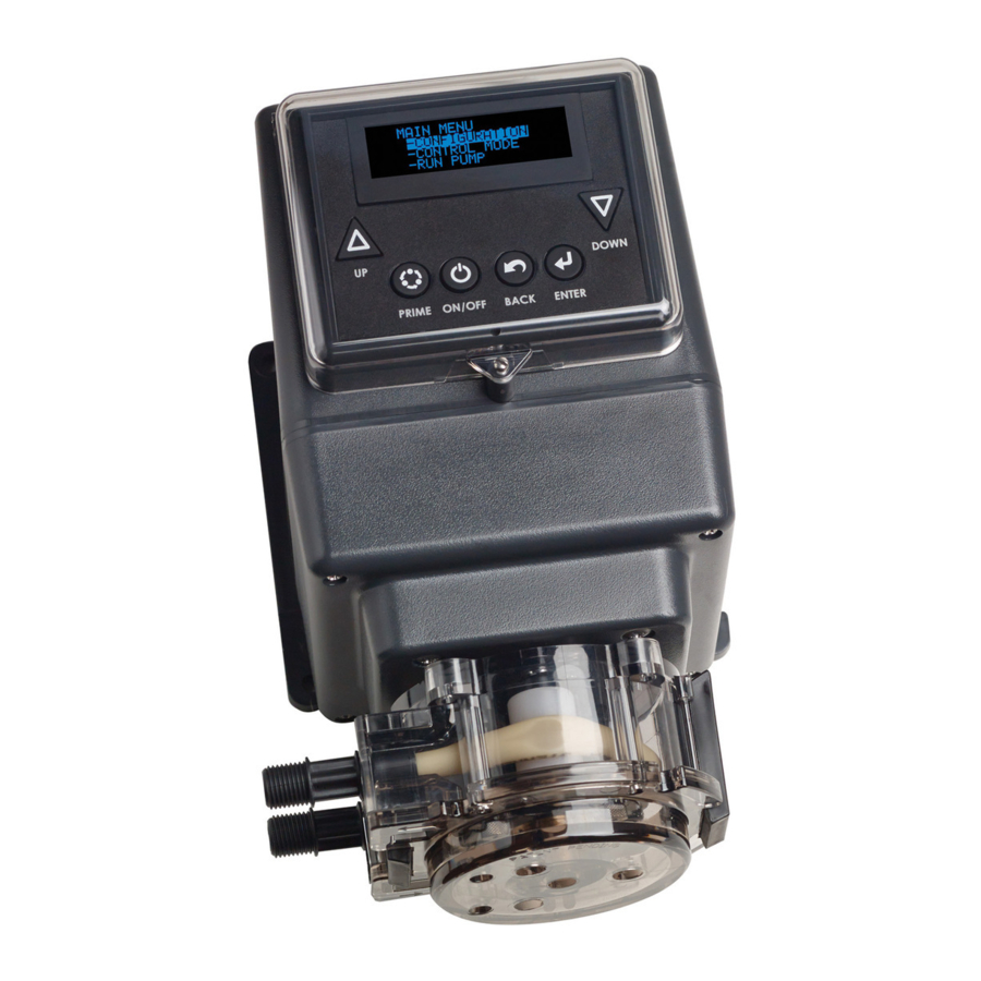
Page 11: General Information
GENERAL INFORMATION The S Series is an advanced peristaltic pump design with multiple programming features and performance indicators. The S Series offers practical and flexible functions for municipal, wastewater and industrial applications. PUMP FEATURES OUTPUT • Brushless DC Motor with ball bearing support •... - Page 12 Output Relays Three individual relays available; rated for 24VDC @ 50mA max. Program communication for: • S Series to back-up S Series • S Series to another device Signal Calibration If factory settings are not sufficient, calibrate the pump using a 4-20mA, 0-10VDC process meter or powered transmitter.
- Page 13 ** Transfer operation from a primary pump to a backup pump via a relay. REMOTE COMMUNICATION CAPABILITY WITH MODBUS RTU over RS-485 Requirements • S Series Pump with firmware version 3.02.02 or higher • Applicable modes of operation: Manual, 4-20mA, 010VDC, or Pulse • Stenner Modbus manual •...
- Page 14 Configuration of the pump parameters should be completed at the initial setup. From the Main Menu, select Configuration and follow Display Brightness Units Clock Calibration Password Tube Timer Reset Totalizer Leak Detect Outputs Modbus Setup Firmware Version Reset Pump. S Series FW 3.02.02 www.stenner.com...
-
Page 15: Configuration
Holding the button causes the numbers to change rapidly. Configuration Display Brightness - Display Brightness 100% Returns to Configuration menu - Units - Clock adjust US and Canada 800.683.2378, International 904.641.1666 S Series FW 3.02.02... - Page 16 Holding the button causes the numbers to change rapidly. Units Configuration - Display Brightness Gallons Returns to Configuration menu. - Units - Clock adjust Units Liters Returns to Configuration menu. adjust S Series FW 3.02.02 www.stenner.com...
- Page 17 CONFIGURATION MENU continued CLOCK Allows the user to set the current day of the week and the time of the day. The time is set in a 24 hour clock format only. NOTE: For the time, the first two digits that control the hour are highlighted together. NAVIGATION Moves up in a menu, toggles Moves down in a menu, toggles...
- Page 18 CONFIGURATION MENU continued CALIBRATION page 1 of 2 Allows user to set the pump’s maximum output. The units displayed in the Calibration submenu are controlled by the setting made in the Units submenu. IMPORTANT: The value entered (in Calibration) for the pump’s maximum output is used to calculate the pump’s required output for the operating mode in Run Pump.
- Page 19 CONFIGURATION MENU continued CALIBRATION page 2 of 2 Allows user to calibrate analog signal inputs and outputs. Connect pump to 4-20mA loop using a process meter or powered transmitter When pump indicates to input When pump indicates to input 4mA, bring loop to 4.0mA 20mA, bring loop to 20.0mA Continued from previous page (or desired level).
- Page 20 If password was If password will return to Configuration menu. accepted. was not accepted. PASSWORD DID NOT PASSWORD MATCH. PLEASE ACCEPTED RE-ENTER PASSWORD Displays message for 3 seconds and To Configuration menu returns to Configuration menu. S Series FW 3.02.02 www.stenner.com...
- Page 21 Tube Timer Reset Tube Timer? - Set Life Timer The timer is NOT reset. - Reset Tube Timer To Tube Timer menu - TO CONFIGURE MENU yes/no select To Configuration menu US and Canada 800.683.2378, International 904.641.1666 S Series FW 3.02.02...
- Page 22 Configuration Reset Totalizer? - Password Totalizer is reset to zero. - Tube Timer To Configuration menu - Reset Totalizer yes/no select Reset Totalizer? Totalizer is NOT reset. To Configuration menu yes/no select S Series FW 3.02.02 www.stenner.com www.stenner.com...
- Page 23 “No” to To Configuration menu allow the pump to continue to run in the event of a leak detect alarm. yes/no Stop pump on alarm? To Configuration menu yes/no US and Canada 800.683.2378, International 904.641.1666 S Series FW 3.02.02...
- Page 24 Repeat Pulse – Manual, 4-20mA, 0-10VDC, Pulse, 7 Day Timer, PPM Feed-Constant or Cycle Timer – Automatically activates the relay when the pump receives the dry contact input signal to repeat this signal to another pump or device. S Series FW 3.02.02 www.stenner.com...
- Page 25 Hall Effect or PPM Feed: Hall Effect ✓ ✓ Low Flow Hall Effect ✓ ✓ Signal Overrun Pulse * Scalable, invertible ** Transfer operation from a primary pump to a backup pump via a relay. US and Canada 800.683.2378, International 904.641.1666 S Series FW 3.02.02...
- Page 26 Relay #X Disable When relays have been Disable Relay. programmed and enabled To Outputs menu . N/DIS or disabled as desired or to exit this menu, choose “To Configuration Menu” and press ENTER. 26 26 S Series FW 3.02.02 www.stenner.com...
- Page 27 Relay #X Relay #1 Leak Detect Low Signal Relay #1 on/off on/off 4-20mA Mode Change Off Continued on on/off 0-10VDC next page Relay #1 High Signal To Outputs menu on/off US and Canada 800.683.2378, International 904.641.1666 S Series FW 3.02.02...
- Page 28 Relay #X Relay #1 Mode Change Leak Detect Hall Effect To Outputs menu on/off on/off Relay #X Relay #1 Mode Change Leak Detect PPM Feed To Outputs menu on/off on/off To Outputs menu S Series FW 3.02.02 www.stenner.com...
- Page 29 Configuration - Outputs FW 3.02.02 To Configuration menu - Modbus Setup - Firmware Version RETURN TO CONFIGURE The display will indicate the pump's software version. US and Canada 800.683.2378, International 904.641.1666 S Series FW 3.02.02...
- Page 30 Main Menu. yes/no yes/no Select “No” and press ENTER to Select “No” to return to return to Configuration menu Configuration menu without without resetting the pump. resetting the pump. To Configuration menu To Configuration menu S Series FW 3.02.02 www.stenner.com...
- Page 31 Holding the button causes the numbers to change rapidly. Configuration - Firmware Version To Main Menu - Reset Pump - Go to Main Menu US and Canada 800.683.2378, International 904.641.1666 S Series FW 3.02.02...
-
Page 32: Control Modes
- Hall Effect - 7 Day Timer - PPM Feed Control Mode - 7 Day Timer - PPM Feed - Cycle Timer Control Mode - PPM Feed - Cycle Timer - Go to Main Menu S Series FW 3.02.02 www.stenner.com... - Page 33 Control Mode Manual Speed - Manual 100% To Main Menu - 4-20mA When ENTER is pressed for the final digit, adjust - 0-10 VDC the display returns to the Main Menu. US and Canada 800.683.2378, International 904.641.1666 S Series FW 3.02.02...
- Page 34 Pump pump programmed to 25% speed to 0% speed @ 4.0mA and 100% programmed to 100% speed @ at 5.0mA and 75% speed at speed @ 20.0mA. 4.0mA and 0% speed @ 20.0mA. 16.0mA. S Series FW 3.02.02 www.stenner.com...
- Page 35 Speed at Max mA When ENTER is pressed for the To Main Menu 100 % final digit, the display will return to the 4-20mA menu. adjust To 4-20mA menu US and Canada 800.683.2378, International 904.641.1666 S Series FW 3.02.02...
- Page 36 Select “Yes” to stop the pump in the Stop Pump on H ALM? event of a high signal alarm. Select “No” to allow the pump to continue running in yes/no the event of a high signal alarm. To 4-20mA menu S Series FW 3.02.02 www.stenner.com...
- Page 37 CONTROL MODES MENU continued 0-10VDC page 1 of 3 Allows user to configure the pump to respond proportionally to a 0-10VDC analog signal. The pump’s speed varies according to the level of the 0-10VDC signal. The response to the signal can be scaled or inverted (refer to Diagram 1, 2 &...
- Page 38 - Go to Main Menu adjust Speed at Max VDC When ENTER is pressed for the final To Main Menu 100 % digit, the display will return to the 0-10VDC menu. adjust To 0-10 VDC menu S Series FW 3.02.02 www.stenner.com...
- Page 39 Stop Pump on H ALM? event of a high signal alarm. Select “No” to allow the pump to continue running yes/no in the event of a high signal alarm. To 0-10VDC menu US and Canada 800.683.2378, International 904.641.1666 S Series FW 3.02.02...
- Page 40 - Program Settings “No” to allow the pump to continue to run - Alarm Settings - Go to Main Menu yes/no in the event of a signal overrun alarm. To Main Menu To Pulse menu S Series FW 3.02.02 www.stenner.com...
- Page 41 100) the pump is to run 010 % while it is activated. adjust To Pulse menu After settings are entered the display returns to the Pulse menu and Alarm Settings can be programmed. US and Canada 800.683.2378, International 904.641.1666 S Series FW 3.02.02...
- Page 42 • The meter’s K factor (pulses per unit of volume) is specified by the meter manufacturer. • Typically, the meter manufacturer will specify a minimum flow rate for the meter. It is recommended the pump minimum process flow rate setting is not set below this point. S Series FW 3.02.02 www.stenner.com...
- Page 43 100 % adjust To Hall Effect menu After the settings are entered, the display returns to Hall Effect menu and Alarm Settings can be programmed. US and Canada 800.683.2378, International 904.641.1666 S Series FW 3.02.02...
- Page 44 Select “Yes” to stop the pump in the Stop Pump on H ALM? event of a high flow alarm. Select “No” to allow the pump to continue running in yes/no the event of a high flow alarm. To Hall Effect menu S Series FW 3.02.02 www.stenner.com...
- Page 45 • The pump uses a battery to maintain the clock when power is removed. • The timer programs entered by the user are stored in non-volatile memory. US and Canada 800.683.2378, International 904.641.1666 S Series FW 3.02.02...
- Page 46 Enable Timer #1. adjust Timer #01 To Main Menu To 7 Day Timer menu Disable To Enables Timers menu After programming and enabling Disable Timer #1. adjust the timers, press enter to return to the Main Menu. S Series FW 3.02.02 www.stenner.com...
- Page 47 Enter the speed % the pump Set Pump Speed is to run for the timed event. 100% adjust After all desired timers are programmed, return to the 7 Day Timer and ENABLE the timers. US and Canada 800.683.2378, International 904.641.1666 S Series FW 3.02.02...
- Page 48 Chemical Concentration % × 10,000 × Specific Gravity Pump Output Required (LPD) × 100 Pump Speed (%) = Max Pump Flow (LPD) • When the pump receives an input signal, it runs at the speed calculated to dose the PPM level programmed. S Series FW 3.02.02 www.stenner.com...
- Page 49 - Variable, Hall Effect - Go to Main Menu To Main Menu After completing Program Settings, select “Go To Main Menu” and press ENTER to return to the Main Menu. US and Canada 800.683.2378, International 904.641.1666 S Series FW 3.02.02...
- Page 50 Set the dose rate in Parts Per Million (ppm). Feed Rate Once the settings have been entered, the _ 10.0 PPM display will return to the PPM Feed menu. yes/no To PPM Feed Constant Flow menu S Series FW 3.02.02 www.stenner.com...
- Page 51 Process LPM × Feed Rate PPM X 1440 Pump Output Required (LPD) = Chemical Concentration % × 10,000 × Specific Gravity Pump Output Required (LPD) × 100 Pump Speed (%) = Max Pump Flow (LPD) US and Canada 800.683.2378, International 904.641.1666 S Series FW 3.02.02...
- Page 52 Stop Pump on H Alarm? pump in the event of a high flow alarm. Select “No” to allow the pump to adjust continue running in the event of a high flow alarm. Go to PPM Variable Flow menu S Series FW 3.02.02 www.stenner.com...
- Page 53 Set the Chemical Specific Gravity. Specific Gravity 1.14 adjust Set the dose rate in parts per Feed Rate million (ppm). _ 10.0 PPM adjust Go to top of PPM Variable Flow menu US and Canada 800.683.2378, International 904.641.1666 S Series FW 3.02.02...
- Page 54 21 to 99,999 seconds. adjust Set the pump speed percent the pump will run. Pump Speed Once these settings have been entered, the 100 % display will return to the Main Menu. adjust To Main Menu S Series FW 3.02.02 www.stenner.com...
- Page 55 To return to the Main Menu, highlight Control Mode “Go To Main Menu” in the Control Mode - PPM Feed - Cycle Timer menu and press ENTER. - Go To Main Menu To Main Menu US and Canada 800.683.2378, International 904.641.1666 S Series FW 3.02.02...
-
Page 56: Operating Display
Turns pump control ON or OFF ON/OFF WARNING: DOES NOT REMOVE POWER BACK Cycles the display to show different units of output ENTER Press and hold for 2 seconds to go to the Main Menu S Series FW 3.02.02 www.stenner.com... - Page 57 PRIME button is pressed (if unlocked or password not set). Manual Prime symbol and 100 will flash while PRIME is pressed. 20.0 Metric is displayed if selected in Configuration Manual 0.83 Manual oz/min 1.77 US and Canada 800.683.2378, International 904.641.1666 S Series FW 3.02.02...
- Page 58 If unlocked or password not set. Prime Pump runs at 100% speed while 4-20mA the PRIME button is pressed (if unlocked or password not set). Metric is displayed if 4-20mA selected in Configuration 40.0 4-20mA 1.66 4-20mA oz/min 3.54 S Series FW 3.02.02 www.stenner.com...
- Page 59 Pump runs at 100% speed while 0-10VDC the PRIME button is pressed (if unlocked or password not set). Metric is displayed if selected 0-10VDC in Configuration 40.0 0-10VDC 1.66 0-10VDC oz/min 3.54 US and Canada 800.683.2378, International 904.641.1666 S Series FW 3.02.02...
- Page 60 PRIME button is pressed (if Pulse unlocked or password not set). While the pump receives a pulse, the display will show a closed contact Pulse Metric is displayed Pulse if selected in 20.0 Configuration Pulse 0.83 Pulse oz/min 1.77 S Series FW 3.02.02 www.stenner.com...
- Page 61 20.0 Hall Effect 0.83 Hall Effect oz/min 1.77 NOTE: Displayed outputs are approximate and may be rounded off. For some units of measure, flows close to zero may display zero. US and Canada 800.683.2378, International 904.641.1666 S Series FW 3.02.02...
- Page 62 If unlocked or password not set. Prime Timer Pump runs at 100% speed while the PRIME button is pressed (if unlocked or password not set). Timer 20.0 Metric is displayed if selected in Configuration Timer 0.83 Timer oz/min 1.77 S Series FW 3.02.02 www.stenner.com...
- Page 63 PRIME button is pressed (if unlocked or password not set). Bar graph along bottom shows rate of incoming pulses from 0 to 100% Metric is displayed if selected in Configuration 20.0 0.83 oz/min 1.77 US and Canada 800.683.2378, International 904.641.1666 S Series FW 3.02.02...
- Page 64 Metric is displayed if closed contact selected in Configuration 20.0 Prime Pump runs at 100% speed while 0.83 the PRIME button is pressed (if unlocked or password not set). oz/min 1.77 S Series FW 3.02.02 www.stenner.com...
- Page 65 Pump runs at 100% speed while CYCLE the PRIME button is pressed (if unlocked or password not set). Metric is displayed if CYCLE selected in Configuration 20.0 CYCLE 0.83 CYCLE oz/min 1.77 US and Canada 800.683.2378, International 904.641.1666 S Series FW 3.02.02...
- Page 66 From any operating display to Alarm Reset if in alarm condition. Hold for If password 0-9, A-Z 2 seconds is correct If password is incorrect INCORRECT PASSWORD Displays for 3 seconds and then returns to previous operating display S Series FW 3.02.02 www.stenner.com...
- Page 67 PASSWORD for 3 seconds and then returns to the 4-20mA beginning of alarm. Low Signal 4-20mA 0-10VDC 0-10VDC High Signal Hall Effect Process High Flow Hall Effect Hall Effect Process Low Flow US and Canada 800.683.2378, International 904.641.1666 S Series FW 3.02.02...
-
Page 68: Connections
Signal cables must be UL, cUL AWM Style 2464 approved with conductors between 28 AWG and 18 AWG. Jacket diameter for small liquid tight must be 0.064" to 0.210". Jacket diameter for large liquid tight must be 0.114" to 0.250". S Series FW 3.02.02 www.stenner.com... - Page 69 Leak Flow Flow Flow 4-20mA Detect Diagram Relay Relay Detect Detect Detect Detect − − External External 12VDC Leak Detect Sensitivity Adjustment Connection FACTORY Terminals USE ONLY Modbus Connection Bottom US and Canada 800.683.2378, International 904.641.1666 S Series FW 3.02.02...
- Page 70 The 12VDC supply from connection #10 is limited to 20mA and is only for powering Hall Effect sensors on turbine or paddlewheel type flow meters. Do not use the 12VDC output for anything else; otherwise, damage to the pump will occur. S Series FW 3.02.02 www.stenner.com...
- Page 71 Relay Relay PPM/Hall − signal) Common 12VDC signal) signal Output 4-20mA Leak Flow Output 4-20mA Leak Flow Flow Relay Relay Detect Detect Detect Detect Detect − − External External 12VDC US and Canada 800.683.2378, International 904.641.1666 S Series FW 3.02.02...
- Page 72 Standby Standby 0-10VDC Signal Hall Relay Relay PPM/Hall − signal) Common 12VDC signal) signal Output Output 4-20mA Leak Leak Flow Flow Flow 4-20mA Detect Relay Relay Detect Detect Detect Detect − − External External 12VDC S Series FW 3.02.02 www.stenner.com...
- Page 73 PPM/Hall Relay Relay − signal) Common 12VDC signal) signal Output Output 4-20mA Leak Leak Flow Flow Flow 4-20mA Relay Relay Detect Detect Detect Detect Detect − − External External 12VDC US and Canada 800.683.2378, International 904.641.1666 S Series FW 3.02.02...
- Page 74 Standby Standby 0-10VDC Signal Hall Relay Relay PPM/Hall − signal) Common 12VDC signal) signal Output Output 4-20mA Leak Flow Flow Flow 4-20mA Leak Detect Relay Relay Detect Detect Detect Detect − − External External 12VDC S Series FW 3.02.02 www.stenner.com...
- Page 75 PPM/Hall Relay Relay − signal) Common 12VDC signal) signal Output Output 4-20mA Leak Leak Flow Flow Flow 4-20mA Relay Relay Detect Detect Detect Detect Detect − − External External 12VDC US and Canada 800.683.2378, International 904.641.1666 S Series FW 3.02.02...
- Page 76 Standby Standby 0-10VDC Signal Hall Relay Relay PPM/Hall − signal) Common 12VDC signal) signal Output Output 4-20mA Leak Leak Flow Flow Flow 4-20mA Detect Relay Relay Detect Detect Detect Detect − − External External 12VDC S Series FW 3.02.02 www.stenner.com...
- Page 77 25%, 50%, & 75%. the loop current – Powered 4-20mA should be 8mA, 12mA, & 16mA respectively. pH Meter – – Pump Injection Point pH Meter Power Supply US and Canada 800.683.2378, International 904.641.1666 S Series FW 3.02.02...
- Page 78 LEAK DETECT page 1 of 3 The S Series pump includes a highly sensitive leak detector. The detector can differentiate between a tube rupture leak and water intrusion. The sensitivity feature reduces the number of false “tube leak” signals due to the pump’s location in a wet environment, outdoors or if subject to hose down cleaning.
- Page 79 - C O NF I G U R A T IO N Leak Detect - C O NT R O L M O D E - R U N P U M P Adjustment Potentiometer Leak Detect Pins US and Canada 800.683.2378, International 904.641.1666 S Series FW 3.02.02...
- Page 80 Manual - C O N F IG U R A T I ON - C O N T R O L M O D E - R U N P U MP Leak Detect Pins S Series FW 3.02.02 www.stenner.com...
-
Page 81: Installation
Inspect tube frequently for leakage, deterioration, or wear. Schedule a regular pump tube maintenance change to prevent chemical damage to pump and/or spillage. Recommended mounting is vertical with pump head pointed downward. US and Canada 800.683.2378, International 904.641.1666 S Series FW 3.02.02... - Page 82 To prevent damage, verify with a volt meter that the receptacle voltage corresponds with the pump voltage. 1. Use the mounting bracket as a template to drill pilot holes in mounting location. 2. Secure bracket with fasteners or wall anchors. Slide pump into bracket. Wall Mounting Bracket Pump Head S Series FW 3.02.02 www.stenner.com...
- Page 83 DIAGRAM Connect only to a branch circuit protected by a ground-fault-circuit-interrupter (GFCI) Wall Mounting Bracket (requires 2 screws) Suction Line Discharge Line Point of Injection Shut-Off Valve Solution Tank US and Canada 800.683.2378, International 904.641.1666 S Series FW 3.02.02...
- Page 84 * For 3/8" connections only. Slide line through 3/8" connecting nut and finger tighten to male end of adapter or pump tube fitting . While firmly holding the adapter or tube fitting, wrench tighten the 3/8" connecting nut one additional half turn. If leak occurs, gradually tighten the 3/8" connecting nut as required S Series FW 3.02.02 www.stenner.com...
- Page 85 DO NOT mix chemicals in the solution container. Follow recommended mixing procedures according to the manufacturer. DO NOT operate pump unless chemical is completely in solution. Turn pump off when replenishing solution. Suction Line 3.5" (9 cm) Weighted " Suction Line Strainer US and Canada 800.683.2378, International 904.641.1666 S Series FW 3.02.02...
- Page 86 Discharge Line 1/4" or 1/2" FNPT Reduction Bushing if needed Injection Fitting or Check Valve Shut-Off Valve Typical Point of Injection DO NOT use thread seal tape on pump tube threads. S Series FW 3.02.02 www.stenner.com...
- Page 87 * For 3/8" connections only. Slide line through 3/8" connecting nut and finger tighten to male end of adapter or pump tube fitting . While firmly holding the adapter or tube fitting, wrench tighten the 3/8" connecting nut one additional half turn. If leak occurs, gradually tighten the 3/8" connecting nut as required US and Canada 800.683.2378, International 904.641.1666 S Series FW 3.02.02...
-
Page 88: Troubleshooting
Cap and insulate the Red wire to prevent is not capped and insulated it from shorting (if not terminated) Load too high or shortened on Maximum loop impedance is 300mA; 4-20mA output Ensure output is not shortened S Series FW 3.02.02 www.stenner.com... - Page 89 Ensure that the setting is such that the unit does not activate with water if not located in a dry location US and Canada 800.683.2378, International 904.641.1666 S Series FW 3.02.02...
- Page 90 Roller assembly broken Replace roller assembly S40 ONLY IMPORTANT: DO NOT TWIST THE TUBE during installation. To ensure it doesn't twist, keep the tube positioned so the printed description stays aligned along the length of the tube. S Series FW 3.02.02 www.stenner.com...
- Page 91 Crushed 1/4" ferrule Replace ferrule 1/4" ferrule in wrong orientation Beveled ends of ferrules face pump. Tubing should bottom into all fittings Missing 3/8" nut sleeve or gripper Replace nut US and Canada 800.683.2378, International 904.641.1666 S Series FW 3.02.02...
- Page 92 DO NOT pull excessively on pump tube. Avoid kinks or damage during tube installation. Inspect the suction and discharge lines, injection point (into pipe), and injection check valve duckbill for blockages after any tube rupture. Clear or replace as required. S Series FW 3.02.02 www.stenner.com...
-
Page 93: Tube Replacement
Remove cover NOTE: The roller assembly needs to be collapsed to remove the tube. Cover Invert cover 3 Lugs Cover Feet Center of roller assembly Align cover feet near tube fitting US and Canada 800.683.2378, International 904.641.1666 S Series FW 3.02.02... - Page 94 Illustration G 12. Reinstall clean tube housing. Check rollers ™ 13. Apply AquaShield to the shaft tip. 14. Install the roller assembly. S Series FW 3.02.02 www.stenner.com...
- Page 95 Be sure the cover is seated with the sleeve bearing on the shaft and is flush with the housing before latching. Illustration I Cover Bushing Apply Aquashield ™ to cover bushing US and Canada 800.683.2378, International 904.641.1666 S Series FW 3.02.02...
- Page 96 5. Inspect the suction and discharge lines, point of injection, and check valve for blockages. Clean and/or replace as required. 6. Reconnect the suction and discharge lines. 7. Prime pump and verify operation. Center tube 8. Place pump in desired operating mode. Secure latches S Series FW 3.02.02 www.stenner.com...
- Page 97 Use caution when disconnecting discharge line from pump. Discharge line may be under pressure. Discharge line may contain chemical. To reduce risk of exposure, the use of proper personal protective equipment is mandatory when working on or near chemical metering pumps. US and Canada 800.683.2378, International 904.641.1666 S Series FW 3.02.02...
-
Page 98: Cleaning The Point Of Injection
Cut off the calcified or blocked section. Clean out accumulated deposits with a #2 Phillips head screwdriver. Periodic inspection and cleaning of the point of injection will maintain proper pump operation and provide maximum tube life. S Series FW 3.02.02 www.stenner.com... -
Page 99: Parts
S3600-4 4-PK QP401-2 2-PK S3QP Latches PART NUMBER DESCRIPTION S4400-1 S4QP Tube Housing with Latches S4400-2 2-PK S4500-1 S4QP Roller Assembly S4500-4 4-PK S4600-1 S4QP Tube Housing Cover S4600-4 4-PK US and Canada 800.683.2378, International 904.641.1666 S Series FW 3.02.02... - Page 100 S4QP Pump Head; #7X Santoprene tube S4107X-2 2-PK NOTE: Confirm material compatibility with the chemical resistance guide in the catalog. Refer to the Flow Rate Outputs chart to match the pump with the correct tube. S Series FW 3.02.02 www.stenner.com...
- Page 101 S4QP Pump Head Service Kit; #7X Santoprene tube NOTE: Confirm material compatibility with the chemical resistance guide in the catalog. Refer to the Flow Rate Outputs chart to match the pump with the correct tube. US and Canada 800.683.2378, International 904.641.1666 S Series FW 3.02.02...
- Page 102 # 1 or 2 for PART NUMBER DESCRIPTION S4005X-2 2-PK ® Santoprene #5X tube S4005X-5 5-PK S4007X-2 2-PK ® Santoprene #7X tube S4007X-5 5-PK Refer to the Flow Rate Outputs chart to match the pump with the correct tube. S Series FW 3.02.02 www.stenner.com...
- Page 103 CHECK VALVES AND MODBUS KIT US and Canada 800.683.2378, International 904.641.1666 S Series FW 3.02.02...
-
Page 104: Wall Mounting Bracket Dimensions
WALL MOUNTING BRACKET DIMENSIONS 1/4" 5" 1/4" NOTICE: Leave 8" of clearance above pump to allow for removal from mounting bracket. S Series FW 3.02.02 www.stenner.com... - Page 105 STENNER PUMP COMPANY 3174 DeSalvo Road Jacksonville, Florida 32246 Phone: 904.641.1666 US Toll Free: 800.683.2378 Fax: 904.642.1012 sales@stenner.com www.stenner.com Hours of Operation (EST): Mon.–Thu. 7:30 am–5:30 pm Fri. 7:00 am–5:30 pm Assembled in the USA © Stenner Pump Company All Rights Reserved IMS 082420...
Need help?
Do you have a question about the S Series and is the answer not in the manual?
Questions and answers