Advertisement
Quick Links
SERVICE MANUAL
AUDIO/VIDEO CONTROL AMPLIFIER
3
2004
MB177
ST ANDBY
ST ANDB Y/ON
PHONES
1
PRECAUTION. . . . . . . . . . . . . . . . . . . . . . . . . . . . . . . . . . . . . . . . . . . . . . . . . . . . . . . . . . . . . . . . . . . . . . . . . 1-2
2
SPECIFIC SERVICE INSTRUCTIONS . . . . . . . . . . . . . . . . . . . . . . . . . . . . . . . . . . . . . . . . . . . . . . . . . . . . . . 1-3
3
DISASSEMBLY . . . . . . . . . . . . . . . . . . . . . . . . . . . . . . . . . . . . . . . . . . . . . . . . . . . . . . . . . . . . . . . . . . . . . . . 1-4
4
ADJUSTMENT . . . . . . . . . . . . . . . . . . . . . . . . . . . . . . . . . . . . . . . . . . . . . . . . . . . . . . . . . . . . . . . . . . . . . . . 1-17
5
TROUBLESHOOTING . . . . . . . . . . . . . . . . . . . . . . . . . . . . . . . . . . . . . . . . . . . . . . . . . . . . . . . . . . . . . . . . . 1-20
All manuals and user guides at all-guides.com
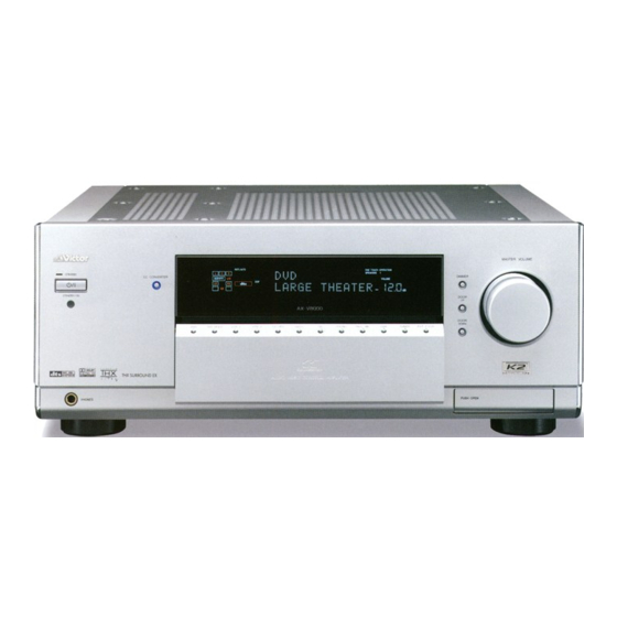
AX-V8000
CC CONVER
AUDIO/VIDEO CONTROL AMPLIFIER
TABLE OF CONTENTS
COPYRIGHT © 2004 VICTOR COMPANY OF JAPAN, LIMITED
UP --------------------------- Korea
LEARN
TRANSMIT
STANDBY
ZONE 1
ZONE 2
ZONE 1
ZONE 2
TV/CATV/DBS
ON/OFF
ON/OFF
STANDBY/ON
ZONE 1
ZONE 2
LEARN
DVD
DVD MULTI
PHONO
VCR 1
VCR 2
TAPE/MD
TV/DBS
VIDEO
FM/AM
ANALOG/DIGITAL
1
2
INPUT
SOUND
4
5
TEST
7
8
/P
CC CONVERTER
MASTER VOLUME
10
0
RETURN
FM MODE
THX
SURROUND
DSP
DIMMER
EX/ES/7.1
ANALOG DIRECT
SLEEP
DIMMER
DOOR
UP
/ REW
PLAY
DOWN
TUNING
U
DOOR
REC
STOP
DOWN
TV/VIDEO
TV VOL
CHANNEL
VOLUME
MUTING
SETUP
MENU
TEXT
SET
DISPLAY
DVD
MENU
LIGHT
DIGITAL
S-VIDEO
VIDEO
L-AUDIO-R
VIDEO
RM-SRXDP20J
REMOTE CONTROL
A/V CONTROL RECEIVER
Area suffix
ON
VCR 1
STANDBY/ON
CD
CDR
EXT 7.1CH
EFFECT
3
LIVENESS
6
9
+
10
100 +
SURR/DSP
OFF
TV
CATV/
DBS
FF/
P
PAUSE
ADJUST
MENU
EXIT
No.MB177
2004/3
Advertisement

Related Manuals for JVC AX-V8000


Summary of Contents for JVC AX-V8000
-
Page 1: Table Of Contents
All manuals and user guides at all-guides.com SERVICE MANUAL AUDIO/VIDEO CONTROL AMPLIFIER MB177 2004 AX-V8000 Area suffix UP --------------------------- Korea LEARN TRANSMIT STANDBY ZONE 1 ZONE 2 ZONE 1 ZONE 2 TV/CATV/DBS VCR 1 ON/OFF ON/OFF STANDBY/ON STANDBY/ON ZONE 1... -
Page 2: Precaution
All manuals and user guides at all-guides.com SECTION 1 PRECAUTION Safety Precautions (1) This design of this product contains special hardware and voltmeter. many circuits and components specially for safety purpos- Move the resistor connection to each exposed metal es. For continued protection, no changes should be made part, particularly any exposed metal part having a return to the original design unless authorized in writing by the path to the chassis, and measure the AC voltage across... -
Page 3: Specific Service Instructions
All manuals and user guides at all-guides.com SECTION 2 SPECIFIC SERVICE INSTRUCTIONS This service manual does not describe SPECIFIC SERVICE INSTRUCTIONS. (No.MB177)1-3... -
Page 4: Disassembly
All manuals and user guides at all-guides.com SECTION 3 DISASSEMBLY Main body section 3.1.1 Removing the top cover (See Fig.1) (1) From the top sides of the main body, remove the nine Side panel (R) Side panel (L) screws A attaching the top cover. Top cover (2) From the back side of the main body, remove the three screws B attaching the top cover. - Page 5 All manuals and user guides at all-guides.com 3.1.3 Removing the front panel assembly (See Figs.3 to 6) • Prior to performing the following procedure, remove the top Front panel assembly cover, side panels and stay bkt. (1) From the top side of the main body, cut off the tie band fixing the wire.
- Page 6 All manuals and user guides at all-guides.com 3.1.4 Removing the rear panel (See Fig.7) • Prior to performing the following procedure, remove the top AC inlet cover, side panels and stay bkt. (1) From the top side on the main body, remove the protect Black cover and the solders from the two solder points on the AC Solder part...
- Page 7 All manuals and user guides at all-guides.com 3.1.7 Removing the system control board (See Figs.10 and 11) • Prior to performing the following procedure, remove the top Power 2 board CN45 Tie bands cover, side panels, stay bkt and front panel assembly. (1) From the top side of the main body, cut off the tie bands fixing the wires.
- Page 8 All manuals and user guides at all-guides.com 3.1.9 Removing the audio signal 1 board (See Fig.13) • Prior to performing the following procedure, remove the top Plastic rivet CN224 CN218 cover, side panels, stay bkt, front panel assembly and rear CN234 CN208 CN223...
- Page 9 All manuals and user guides at all-guides.com 3.1.11 Removing the main board (See Figs.16 and 17) • Prior to performing the following procedure, remove the top Regulator board Power 2 board cover, rear panel, front panel assembly, Y/C separator board, CN11 CN62 CN44...
- Page 10 All manuals and user guides at all-guides.com 3.1.14 Removing the power transformer 1 with the power 2 board (See Fig.19) • Prior to performing the following procedure, remove the top Power transformer 1 Power 2 board cover, side panels, stay bkt and regulator board. (1) From top side of the main body, disconnect the wire from the connector CN46...
- Page 11 All manuals and user guides at all-guides.com 3.1.17 Removing the power transformer 3 with the power 1 board (See Fig.22) • Prior to performing the following procedure, remove the top Power transformer 3 cover, side panels, stay bkt, regulator board, power Power 1 board transformer 1 and power transformer 2.
- Page 12 All manuals and user guides at all-guides.com 3.1.19 Removing the head phone board (See Figs.24 and 25) • Prior to performing the following procedures, remove the top cover, side panels, stay bkt and front panel assembly. (1) From the top side of the main body, disconnect the wires Lug wire Bracket from the connector...
- Page 13 All manuals and user guides at all-guides.com Power amp. assembly section • Remove the power amp. assembly from the main body. (See "Removing the power amp. assembly".) 3.2.1 Removing the relay board & Rch amp. board & Lch amp. board & Cch amp. board & SL/SRch amp. board (See Figs.1 to 3) (1) From the top side of the amp.
- Page 14 All manuals and user guides at all-guides.com 3.2.2 Removing the thermal SW 2 board (See Fig.4) • Prior to performing the following procedure, remove the relay board and the each amp. board of Lch, Cch, SL/SRch, Rch. Heat sink (1) From the top side of the amp. assembly, remove the screw B attaching the thermal SW 2 board.
- Page 15 All manuals and user guides at all-guides.com Front panel assembly section • Remove the front panel assembly from the main body. (See "Removing the front panel assembly".) 3.3.1 Removing the FL display board & front AV in board (See Figs.1 and 2) (1) From the front side of the front panel assembly, pull out the volume knob to the forward and remove the nut a attaching the FL display board.
- Page 16 All manuals and user guides at all-guides.com 3.3.2 Removing the power switch board & front DIGITAL in board & motor assembly (See Fig.3) • Prior to performing the following procedure, remove the FL display board. Power switch board (1) From the reverse side of the front panel assembly, remove the four screws C attaching the power switch board and take out the power switch board.
-
Page 17: Adjustment
All manuals and user guides at all-guides.com SECTION 4 ADJUSTMENT Adjustment of idling current Measuring point Alignment point Measuring condition B903 & B904 VR701 No load and No signal.Rated line voltage SURROUND : OFF B911 & B912 VR751 Room temperature : 20 to 25 ºC B907 &... - Page 18 All manuals and user guides at all-guides.com Idling Current graph (1/2) SL ch / SR ch SL ch SR ch Time(Min) SBL ch / SBR ch SBL ch SBR ch Time(Min) 1-18 (No.MB177)
- Page 19 All manuals and user guides at all-guides.com Idling Current graph (2/2) L ch / R ch L ch R ch Time(Min) C ch Time(Min) (No.MB177)1-19...
-
Page 20: Troubleshooting
All manuals and user guides at all-guides.com SECTION 5 TROUBLESHOOTING This service manual does not describe TROUBLESHOOTING. 1-20 (No.MB177) - Page 21 All manuals and user guides at all-guides.com (No.MB177)1-21...
- Page 22 All manuals and user guides at all-guides.com VICTOR COMPANY OF JAPAN, LIMITED AV & MULTIMEDIA COMPANY AUDIO/VIDEO SYSTEMS CATEGORY 10-1,1chome,Ohwatari-machi,Maebashi-city,371-8543,Japan (No.MB177) Printed in Japan...
- Page 23 All manuals and user guides at all-guides.com SCHEMATIC DIAGRAMS AUDIO/VIDEO CONTROL AMPLIFIER AX-V8000 CD-ROM No.SML200402 Area suffix UP --------------------------- Korea LE AR N TR ANS MIT S TANDBY ZONE 1 ZONE 2 ZONE 1 ZONE 2 TV/CA TV/DBS VCR 1...
- Page 24 All manuals and user guides at all-guides.com In regard with component parts appearing on the silk-screen printed side (parts side) of the PWB diagrams, the parts that are printed over with black such as the resistor ( ), diode ( ) and ICP ( ) or identified by the "...
- Page 25 All manuals and user guides at all-guides.com Block diagram Pre main Pre main amp section (Lch/SBLch amp) DSP 1 section DSP 2 section Audio signal input 2 Power amp section Power amp section(Speaker) amp section IC681 section IC635, IC640 IC673 (Relay) FRONT DIGITAL...
- Page 26 All manuals and user guides at all-guides.com Standard schematic diagrams Primary / Regulator section TW661 WR65 CN65 CN63 2SD2394/EF/ D101 QMR0008-001 1SS133-T2 WR102 2SD2394/EF/ 2SC1740S/RS/-T EP62 RY101 QGB2510J1-07 QSK0131-001 DSP_RESET 2SC1740S/RS/-T DSP_COMMAND DSP_STATUS 0.0022 DSP_CLOCK DSP_RESET WR64 CN64 QMR0007-001 RY102 1SS133-T2 DSP_READY DSP_COMMAND...
- Page 27 All manuals and user guides at all-guides.com Pre main amp section CN821 R723 R1623 C709 R706 R707 WR711 R720 C711 TH701 47/100 Q716 C1609 Q706 QAD0010-351 2SC2412K/RS/-X CN701 KTA1267/YG/ WR714 R1620 C1611 R717 47/100 TH771 R735 R1606 R1607 Q1616 CN704 Q1606 QAD0010-351 2SC2412K/RS/-X...
- Page 28 All manuals and user guides at all-guides.com Power amp section C1981 Q712 1/50 2SC4883A/Y/ D716 D1716 MTZJ33C MTZJ33C Q1714 R1903 R1943 R726 R1726 Q1712 2SC3858/PG/ 2SC4883A/Y/ RY901 Q714 CN741 2SC3858/PG/ R739 R1739 R1901 L701 R1941 WR731 2.7K 2.7K Q1901 QSK0109-001 Q1941 2SC3906K/RS/ R741...
- Page 29 RY274 C2403 QSK0112-001 R2353 R2354 C225 2.4K C2266 22/50 1/50 10/80 ZIST.C IC221 5.1K 5.1K TC9459F-X R300 Q292 R277 R2260 2SC3576-JVC-T A/D.CC C2405 C2419 IC271 47/50 0.022 NJM5532M-D-XE DSP.L C2252 IC241 NJM4580E-W 22/50 RY272 QSK0112-001 C291 C2406 C2420 47/50 0.022...
- Page 30 SrB-R C337 C338 330P 330P R363 Q342 Fr-L DTA114YKA-X Q332 Fr-R DTC114YKA-X C363 CENTER R346 22/50 R345 R2315 C2315 Q324 2SC3576-JVC R364 Q323 330P 2SD2144S/VW/ 470K R348 R347 Q343 DTA114YKA-X R365 IC311 SAA6588 C365 22/50 SrB-L R1351 R366 R2313 470K...
- Page 31 All manuals and user guides at all-guides.com Video signal input 1 section C4702 47/25 C4854 47/25 C4701 0.01 C4855 0.01 Q4701 IC471 BU4051BC DTC114EKA-X MAIN1 IC483 NJM2509V-W R4842 Q4702 DTC114EKA-X VCR1R-S12 R4704 MAIN2 R4626 VCR2R-S12 R4705 C4501 C4521 R4501 0.01 0.047 TV-C MONI-S12...
- Page 32 All manuals and user guides at all-guides.com Video signal input 2 section C411 1/50 C413 1/50 C408 47/25 C414 47/25 C409 0.01 C415 0.01 IC401 NJM2286V-W IC402 MM1118XF-X MAIN3 MAIN1 MAIN1 C403 R410 MAIN2 R437 C449 1/50 R403 C447 YCOUT Q413 120p DTC114YKA-X...
- Page 33 All manuals and user guides at all-guides.com Video signal input 3 section R1530 R512 R501 R1533 RY501 D501 1SS355-X R565 R502 R561 R1531 RY561 D561 Q501 1SS355-X KRC105M-T R1534 R562 R1532 Q561 R513 KRC105M-T R503 R1535 RY502 D502 1SS355-X R566 R563 IC502 UPC1830GT-XE...
- Page 34 All manuals and user guides at all-guides.com Sytem control LSI / FL display section (SHEET 1) (SHEET 1) WR961 WR962 QJK014-087002 QJK014-083003 S1051 S1052 QSW0851-001 QSW0851-001 RA966 QRB169J-104 WR977 QJK030-042404 CN977 D1003 QGA2001F1-04 11ES2-T4 DOOR_DET3 DOOR_DET1 AV_VCR AV_VCR DOOR_DET2 D1002 D1004 D1001 C1013...
- Page 35 All manuals and user guides at all-guides.com DSP 1 section A.GND AD/DIR IC801 C3610 TC5081BP IC681 SN74LV157APW-X C3811 IC802 R3813 IC831 SN74LVC1GU04K-X PQ20VZ11-X R3601 R3811 C3618 A.BCK LC801 NQR0450-001X R3814 R3815 LRCK S_MCK R3602 IC810 R3812 SN74LVC1G04K-X C3608 L3601 C3609 A.LRCK 100p 0.39...
- Page 36 All manuals and user guides at all-guides.com DSP 2 section LFE_CONT LFE_MIX C3154 47/50 C3152 R3106 100/25 R3112 C3144 R3171 R3126 R3114 C3112 R3172 R3148 R3146 R3173 R3108 1.6k 180p IC632 C3124 R3174 NJM5532M-D-XE R3110 1000P C3171 R3122 R3124 3.6k R3144 100p C3116...
- Page 37 All manuals and user guides at all-guides.com Printed circuit board Amp board Forward side (Power amp board) R1777 CN723 CN823 TW701 D774 TW702 D773 C1773 C1775 C1777 RY751 R1978 D746 D796 D846 C775 C776 C773 C774 CN701 WR733 WR735 WR732 WR737 WR736 WR731...
- Page 38 All manuals and user guides at all-guides.com Amp board Forward side Reverse side (Relay board) (Speaker relay board) (Relay board) (Speaker relay board) R1795 R1795 L1751 C1786 C1785 C1786 C1785 R1796 R1796 RY905 C1737 C1787 CN742 C1788 ST903 HS701 C1637 C1984 RY904 R1693...
- Page 39 All manuals and user guides at all-guides.com Amp board Forward side Reverse side R719 R1769 WR711 R719 C708 C1758 WR717 C708 R1769 C1758 (Lch amp. board) (Rch amp. board) (Lch amp. board) (Rch amp. board) D703 D1753 D1753 D703 R1768 WR717 R718 IC604...
- Page 40 All manuals and user guides at all-guides.com Audio & Video board Foward side Reverse side (DSP 2 board) (DSP 2 board) WR632 CN651 Q3207 Q3107 CN652 C3012 C3033 R3258 C3011 R3230 R3158 C3154 R3157 R3491 R3228 R3235 C3031 R3457 C3232 C3253 Q3105 C3126...
- Page 41 All manuals and user guides at all-guides.com Audio & Video board Foward side Reverse side (D5 video board) (D5 video board) (Door input board) (Door input board) J502 J501 J503 J503 J502 J501 Q506 RY506 RY504 Q506 RY503 RY506 C1520 RY505 R1523 RY505...
- Page 42 All manuals and user guides at all-guides.com DSP board Reverse side Foward side (DSP 1 board) (DSP 1 board) C3652 IC801 R3603 IC831 IC801 C3602 R3812 R3816 IC681 L3601 BC802 IC810 IC802 R3815 R3601 R3817 C3662 WR636 R3818 WR636 C3811 Q3651 R3814 R3652...
- Page 43 All manuals and user guides at all-guides.com Power supply board (Main board) CN13 CN14 CN11 CN12 (Power 2 board) (Power supply / fuse board) CN25 WR26 CN15 (Power transformer 2 board) (Power transformer 1 board) CN47 RY104 CN46 WR81 WR12 RY103 CN45 CN44...
- Page 44 All manuals and user guides at all-guides.com Front board (Power switch board) WR970 (Door switch board) (Compu link board) R1032 R1201 D1202 D1031 CN301 D1201 C1201 S1024 R1210 D1034 R1209 IC301 R1208 (Front AV in board) S1041 R1205 Q1202 D1203 IC964 WR301 J471...
- Page 45 All manuals and user guides at all-guides.com Audio & Video signal I/O board Foward side (Audio signal 1 board) CN201 WR204 CN224 CN207 SW201 R2273 CN223 CN234 CN208 CN218 C2053 R276 C2251 CN203 C222 R2274 R2353 C210 C212 RY278 RY274 R2623 C2051 R2051...
- Page 46 All manuals and user guides at all-guides.com Audio & Video signal I/O board Foward side Reverse side (Audio signal 2 board) (Audio signal 2 board) R2313 X311 R2311 X311 R2314 C363 R363 C363 Q332 R364 IC311 Q342 IC311 C2312 C2317 C365 R365 C365...
- Page 47 All manuals and user guides at all-guides.com Audio signal I/O board Audio signal 3 board J701 J702 C7701 C7716 C7704 C7709 C7708 C7705 C7714 C7711 C7713 C7712 C7736 C7734 C7740 C7735 C7733 C7739 C7738 C7737 C7751 C7752 C7758 C7755 C7753 C7754 C7756 C7757...
- Page 48 All manuals and user guides at all-guides.com VICTOR COMP ANY OF J AP AN, LIMITED AV & MULTIMEDIA COMPANY AUDIO/VIDEO SYSTEMS CATEGORY 10-1,1chome,Ohwatari-machi,Maebashi-city,371-8543,Japan Printed in Japan (No.MB177SCH)
- Page 49 All manuals and user guides at all-guides.com PARTS LIST [ AX-V8000 ] * All printed circuit boards and its assemblies are not available as service parts. Area suffix UP ---------------------------- Korea - Contents - 3- 2 Exploded view of general assembly and parts list (Block No.M1) 3- 6 Electrical parts list (Block No.01~07)
- Page 50 All manuals and user guides at all-guides.com Exploded view of general assembly and parts list Block No. 9.5 0.3mm e' J...
- Page 51 All manuals and user guides at all-guides.com...
- Page 52 FELT SPACER LV40247-001A FOOT (x3) LV10536-026A FRONT BASE QYSPST3016M TAP SCREW M3 x 16mm(x3) LV30225-0D5A SPACER LV10541-003A SIDE BKT(L) LV43855-001A JVC MARK QYSBSGG3008E TAPPING SCREW 3mm x 8mm(x4) E60912-003 SPEED NUT E73967-006 SPACER (x4) LV43263-002A K2 MARK LV10542-004A TRANS BASE E408131-001...
- Page 53 All manuals and user guides at all-guides.com Symbol No. Part No. Part Name Description Local QYSBSGY3008E SPECIAL SCREW 3mm x 8mm QYSBSGY3008E SPECIAL SCREW 3mm x 8mm(x4) QYSBSGY3008E SPECIAL SCREW 3mm x 8mm(x4) QYSBSGY3008E SPECIAL SCREW 3mm x 8mm(x3) QYSBSGY3008E SPECIAL SCREW 3mm x 8mm(x4)
- Page 54 All manuals and user guides at all-guides.com Electrical parts list Power amp. board Block No. [0][1][0][0] Symbol No. Part No. Part Name Description Local Symbol No. Part No. Part Name Description Local Q1631 2SC2412K/RS/-X TRANSISTOR Q1632 DTA124EKA-X DIGI TRANSISTOR IC601 VC5022-2 Advanced super A...
- Page 55 All manuals and user guides at all-guides.com Symbol No. Part No. Part Name Description Local Symbol No. Part No. Part Name Description Local D716 MTZJ33C-T2 Z DIODE D1921 1SS133-T2 DIODE D717 MTZJ33C-T2 Z DIODE D1931 1SS133-T2 DIODE D745 F10P20F FR DIODE D1941...
- Page 56 All manuals and user guides at all-guides.com Symbol No. Part No. Part Name Description Local Symbol No. Part No. Part Name Description Local C835 QFLC1HJ-473Z M CAPACITOR 0.047uF 50V J C1758 QFN31HJ-472Z M CAPACITOR 4700pF 50V J C836 QFLC1HJ-473Z M CAPACITOR 0.047uF 50V J...
- Page 57 All manuals and user guides at all-guides.com Symbol No. Part No. Part Name Description Local Symbol No. Part No. Part Name Description Local R752 QRA14CF-1003Y CMF RESISTOR 100kΩ 1/4W F R837 NRSA02J-241X MG RESISTOR 240Ω 1/10W J R753 QRA14CF-1001Y CMF RESISTOR 1kΩ...
- Page 58 All manuals and user guides at all-guides.com Symbol No. Part No. Part Name Description Local Symbol No. Part No. Part Name Description Local R1675 QRJ146J-271X UNF C RESISTOR 270Ω 1/4W J R1767 QRE141J-331Y C RESISTOR 330Ω 1/4W J R1676 QRJ146J-1R0X UNF C RESISTOR...
- Page 59 All manuals and user guides at all-guides.com Symbol No. Part No. Part Name Description Local Symbol No. Part No. Part Name Description Local L1701 QQR1339-001 COIL WR731 WJK0149-001A E-SI C WIRE C-B L1751 QQR1339-001 COIL WR736 WJK0150-001A E-SI C WIRE C-B CN701 QGA3901C1-06 CONNECTOR...
- Page 60 2SA933S/RS/-T TRANSISTOR D468 1SS133-T2 DIODE Q271 2SD468/BC/-T TRANSISTOR D469 1SS133-T2 DIODE Q272 2SD468/BC/-T TRANSISTOR D470 1SS133-T2 DIODE Q291 2SC3576-JVC-T TRANSISTOR D2501 1SS355-X SI DIODE Q292 2SC3576-JVC-T TRANSISTOR D2502 1SS355-X SI DIODE Q293 2SC3576-JVC-T TRANSISTOR D2503 1SS355-X SI DIODE Q294 2SD2144S/VW/-T...
- Page 61 All manuals and user guides at all-guides.com Symbol No. Part No. Part Name Description Local Symbol No. Part No. Part Name Description Local C282 QEZ0538-476Z C CAPACITOR 47uF C445 NCS31HJ-470X C CAPACITOR 47pF 50V J C285 NCB31HK-561X C CAPACITOR 560pF 50V K C446 QFN31HJ-682Z...
- Page 62 All manuals and user guides at all-guides.com Symbol No. Part No. Part Name Description Local Symbol No. Part No. Part Name Description Local C4515 QETN1HM-105Z E CAPACITOR 1uF 50V M R225 QRJ146J-331X UNF C RESISTOR 330Ω 1/4W J C4516 NCF31HZ-103X C CAPACITOR...
- Page 63 All manuals and user guides at all-guides.com Symbol No. Part No. Part Name Description Local Symbol No. Part No. Part Name Description Local R305 NRSA63J-103X MG RESISTOR 10kΩ 1/16W J R438 NRSA63J-471X MG RESISTOR 470Ω 1/16W J R306 NRSA63J-103X MG RESISTOR 10kΩ...
- Page 64 All manuals and user guides at all-guides.com Symbol No. Part No. Part Name Description Local Symbol No. Part No. Part Name Description Local R2502 NRSA63J-333X MG RESISTOR 33kΩ 1/16W J R4624 NRSA63J-152X MG RESISTOR 1.5kΩ 1/16W J R2503 NRSA63J-104X MG RESISTOR 100kΩ...
- Page 65 All manuals and user guides at all-guides.com Symbol No. Part No. Part Name Description Local Symbol No. Part No. Part Name Description Local RY351 QSK0151-001 RELAY 1SS133-T2 DIODE SW201 QSW0511-001 PUSH SWITCH 1SS133-T2 DIODE WR204 QJK016-091804 SIN CR C-B WIRE 1SS133-T2 DIODE WR318...
- Page 66 All manuals and user guides at all-guides.com Symbol No. Part No. Part Name Description Local Symbol No. Part No. Part Name Description Local QRE141J-821Y C RESISTOR 820Ω 1/4W J FS603 VYSH101-009 SPACER QRE141J-101Y C RESISTOR 100Ω 1/4W J FS604 VYSH101-009 SPACER...
- Page 67 All manuals and user guides at all-guides.com Symbol No. Part No. Part Name Description Local Symbol No. Part No. Part Name Description Local D1031 SLR-342VC-T R1052 NRSA63J-102X MG RESISTOR 1kΩ 1/16W J D1034 SELU2E10C/EF/ R1053 NRSA63J-122X MG RESISTOR 1.2kΩ...
- Page 68 All manuals and user guides at all-guides.com Symbol No. Part No. Part Name Description Local Symbol No. Part No. Part Name Description Local R1171 NRSA63J-221X MG RESISTOR 220Ω 1/16W J S1027 QSW0683-001Z PUSH SW R1172 NRSA63J-221X MG RESISTOR 220Ω...
- Page 69 All manuals and user guides at all-guides.com Symbol No. Part No. Part Name Description Local Symbol No. Part No. Part Name Description Local IC807 SN74LVC1G04K-X Inverter C3552 NCB31HK-103X C CAPACITOR 0.01uF 50V K Quadruple 2-input C3553 NCB31HK-103X C CAPACITOR 0.01uF 50V K IC808 SN74AHCT32PW-X...
- Page 70 All manuals and user guides at all-guides.com Symbol No. Part No. Part Name Description Local Symbol No. Part No. Part Name Description Local C3752 NEA71CM-106X E CAPACITOR 10uF 16V M C4869 NCS31HJ-330X C CAPACITOR 33pF 50V J C3753 NCF31CZ-104X C CAPACITOR 0.1uF 16V Z...
- Page 71 All manuals and user guides at all-guides.com Symbol No. Part No. Part Name Description Local Symbol No. Part No. Part Name Description Local R3722 NRSA63J-221X MG RESISTOR 220Ω 1/16W J R4852 NRSA63J-561X MG RESISTOR 560Ω 1/16W J R3731 NRSA63J-221X MG RESISTOR 220Ω...
- Page 72 All manuals and user guides at all-guides.com Symbol No. Part No. Part Name Description Local Symbol No. Part No. Part Name Description Local Q7097 2SC3422/OY/ TRANSISTOR R7737 QRV12DF-1000 CMF RESISTOR 100Ω 1/2W F R7738 QRV12DF-1000 CMF RESISTOR 100Ω 1/2W F C7191 QDVB1EZ-103Y C CAPACITOR...
- Page 73 All manuals and user guides at all-guides.com Symbol No. Part No. Part Name Description Local Symbol No. Part No. Part Name Description Local Data selector / C506 QETN1AM-227Z E CAPACITOR 220uF 10V M IC651 SN74LV157APW-X Multiplexers C507 QETN1AM-227Z E CAPACITOR 220uF 10V M IC654...
- Page 74 All manuals and user guides at all-guides.com Symbol No. Part No. Part Name Description Local Symbol No. Part No. Part Name Description Local C3036 NCB31CK-104X C CAPACITOR 0.1uF 16V K C3251 QEZ0629-107 E.CAPA AWF 100uF C3037 QETN1HM-105Z E CAPACITOR 1uF 50V M C3252 QEZ0629-107...
- Page 75 All manuals and user guides at all-guides.com Symbol No. Part No. Part Name Description Local Symbol No. Part No. Part Name Description Local C3423 QFN31HJ-122Z M CAPACITOR 1200pF 50V J R599 NRSA63J-104X MG RESISTOR 100kΩ 1/16W J C3424 QFN31HJ-122Z M CAPACITOR 1200pF 50V J...
- Page 76 All manuals and user guides at all-guides.com Symbol No. Part No. Part Name Description Local Symbol No. Part No. Part Name Description Local R3033 NRSA63J-151X MG RESISTOR 150Ω 1/16W J R3190 NRSA63J-221X MG RESISTOR 220Ω 1/16W J R3034 NRSA63J-151X MG RESISTOR 150Ω...
- Page 77 All manuals and user guides at all-guides.com Symbol No. Part No. Part Name Description Local Symbol No. Part No. Part Name Description Local R3308 QRV12DF-1602 CMF RESISTOR 16kΩ 1/2W F R3433 NRSA63J-103X MG RESISTOR 10kΩ 1/16W J R3309 NRSA63J-362X MG RESISTOR 3.6kΩ...
- Page 78 All manuals and user guides at all-guides.com Symbol No. Part No. Part Name Description Local LC640 NQR0450-001X EMI FILTER 0.022uF 50V M LC645 NQR0450-001X EMI FILTER 0.022uF 50V M LC650 NQR0450-001X EMI FILTER 0.022uF 50V M RY501 QSK0150-001 RELAY RY502 QSK0150-001 RELAY...
- Page 79 All manuals and user guides at all-guides.com < MEMO > 3-31...
- Page 80 All manuals and user guides at all-guides.com Packing materials and accessories parts list Block No. 3-32...
- Page 81 All manuals and user guides at all-guides.com Packing and accessories Block No. [M][3][M][M] Symbol No. Part No. Part Name Description Local RM-SAXV8000U REMOCON LV42570-001A SHEET LV30256-007A SHEET ------------------- AL BATTERY (x2) BT-56013-1 WARRANTY CARD A 6 QMPS290-200-JC POWER CORD 2m BLACK LV30256-013A SHEET...