Table of Contents
Advertisement
Quick Links
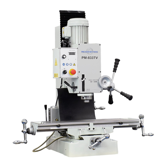
Model PM-833TV
Heavy duty precision milling machine
VFD: Infinitely variable spindle speed, 50 to 3200 rpm
Single-range belt drive, no gears
8-1/4 x 33 inch table
One-shot lubrication
220 Vac single-phase motor
± 90 degree tiltable headstock
Ground inch-pitch X & Y axis leadscrews
Weight (including stand) 880 lbs
PM-833TV variable speed precision milling machine
The PM-833TV is manufactured in Taiwan
1
PM-833TV 4-13-21V1.indd
Copyright © 2021 Quality Machine Tools, LLC
Advertisement
Table of Contents

Related Manuals for Precision matthews PM-833TV


Summary of Contents for Precision matthews PM-833TV
- Page 1 220 Vac single-phase motor ± 90 degree tiltable headstock Ground inch-pitch X & Y axis leadscrews Weight (including stand) 880 lbs PM-833TV variable speed precision milling machine The PM-833TV is manufactured in Taiwan PM-833TV 4-13-21V1.indd Copyright © 2021 Quality Machine Tools, LLC...
- Page 2 1. Insert a 1/2" or 12 mm (clear- ance) ID collar under the cap to fill the gap. 2. Shorten the drawbar, see the end of Section 4, Maintenance. PM-833TV 4-13-21V1.indd Copyright © 2021 Quality Machine Tools, LLC...
-
Page 3: Section 1 Features & Specifications
Unlike most other bench-style mills, the PM-833TV comes with a one-shot lubrication system, a great time saver in situations where continuous duty is a requirement. All sliding surfaces are hand-scraped for precise fit, good oil retention and ultra-smooth operation. - Page 4 PM-833TV SPECIFICATIONS Dimensions Weight, including stand 880 lb net,1030 lb shipping Floor space required W 72 in. x D 35 in Headroom required Normal operations 75 in. (max height 86 in) Stand footprint W 17-3/4 in. x D 29-3/4 in.
-
Page 5: Section 2 Installation
4. The spindle speed control is fully counter-clockwise — lowest speed setting. If in doubt about any of the above, refer to the following installation instructions, and to Section 3, Using the Mill. PM-833TV 4-13-21V1.indd Copyright © 2021 Quality Machine Tools, LLC... - Page 6 One-shot lube reservoir Headstock motion should stop instantly, re- suming when the switch plunger is released. Figure 2-2 Z-axis limit stops Z-axis motor option, inset (File photo, Model PM-833) PM-833TV 4-13-21V1.indd Copyright © 2021 Quality Machine Tools, LLC...
- Page 7 UNCRATING THE MILL The PM-833TV mill and stand are usually shipped in separate containers. In special instances, the mill and stand may be shipped pre-assembled Before moving the mill, check the two Special Precautions on the pre- ceding page: 1. Oil line protruding from the column, Fig- ure 2-1, and;...
-
Page 8: Power-Up Procedure
If the mill is in a location where dust or debris can fall from the ceiling, it is a good idea to cover the column with a 7-1/2 x 3-1/2" plate of scrap material. Figure 2-7 Front panel PM-833TV 4-13-21V1.indd Copyright © 2021 Quality Machine Tools, LLC... - Page 9 1. Rotate the speed control knob fully counter-clock- 5. Test the fast raise/lower function (RAPID push-but- wise, then clockwise about 45 degrees to set a low ton on the motor). speed. PM-833TV 4-13-21V1.indd Copyright © 2021 Quality Machine Tools, LLC...
-
Page 10: Test Run Procedure
The machine should now be ready for normal opera- tions. Figure 2-13 Headstock power assist Limit switch Figure 2-14 Z axis limit switch & stops PM-833TV 4-13-21V1.indd Copyright © 2021 Quality Machine Tools, LLC... -
Page 11: Section 3 Using The Mill
• Clean the machine routinely – remove chips by brush or vacuum, not com- pressed air (which can force debris into the ways). No list of precautions can cover everything. You can never be too careful! PM-833TV 4-13-21V1.indd Copyright © 2021 Quality Machine Tools, LLC... -
Page 12: Installing & Removing Tooling
Excessive cutter noise, chatter, poor finish and tool wear are often the result of too high a feed rate, and/or too high a spindle speed. If unsure, go slow! Figure 3-5 Spindle collar PM-833TV 4-13-21V1.indd Copyright © 2021 Quality Machine Tools, LLC... - Page 13 This means that the handwheel must always be turning in the same direction throughout the entire process, from setting a reference level to sub- sequent cutting passes at specific depths. Figure 3-8 Headstock adjust handle PM-833TV 4-13-21V1.indd Copyright © 2021 Quality Machine Tools, LLC...
- Page 14 Positioning the headstock A micrometer collar graduated in 0.001" divisions, 0.1" per revolution, allows the headstock elevation to be ac- curately set when adjusted by hand. PM-833TV 4-13-21V1.indd Copyright © 2021 Quality Machine Tools, LLC...
-
Page 15: Moving The Table
ALIGN company (Taiwan), Figure 3-14. If a power assist unit is installed on the X-axis, the han- dle at the right-hand end of the table is disengaged from PM-833TV 4-13-21V1.indd Copyright © 2021 Quality Machine Tools, LLC... - Page 16 6. While holding the Y-axis handwheel to prevent any movement, zero the dial. 7. Raise the quill, then rotate the handwheel exactly one full turn counter-clockwise (0.1”) to bring the reference edge forward to the spindle centerline. PM-833TV 4-13-21V1.indd Copyright © 2021 Quality Machine Tools, LLC...
- Page 17 Figure 3-16 One of three headstock attachment nuts Remove the bottom cover for access. The other two nuts are in pock- ets on the sides of the headstock casting.. PM-833TV 4-13-21V1.indd Copyright © 2021 Quality Machine Tools, LLC...
- Page 18 4. Set a 1-2-3 block (or other precision-ground block) ply tightening the bolts can affect the tram). on the table under the indicator probe. 5. Lower the spindle using fine downfeed to give an PM-833TV 4-13-21V1.indd Copyright © 2021 Quality Machine Tools, LLC...
- Page 19 For routine milling operations, the workpiece is usually Most precision vises come with key slots on the under- held in a precision vise. For the PM-833TV, a 4” vise is side, machined exactly parallel to the fixed jaw. Key highly suitable. “Indicating” means checking the align- slots, Figure 3-21, can be a great time saver.
-
Page 20: Section 4 Maintenance
Raise and lower the quill to expose the remainder of the working surfaces, locking and cleaning at each setting. Figure 4-2 Quill rack PM-833TV 4-13-21V1.indd Copyright © 2021 Quality Machine Tools, LLC... -
Page 21: Gib Adjustment
Figure 4-5 Gib screw: Y-axis, back 1. Lower the headstock to bring the spindle nose close to the table. Don't overdo this — be sure that the PM-833TV 4-13-21V1.indd Copyright © 2021 Quality Machine Tools, LLC... - Page 22 3. Replace and tighten the self-locking nut. 4. Unlock the quill to test the return spring function. Early models of the PM-833TV came with a hex lock nut, Fig- Re-tension if necessary to achieve the desired ure 4-10, to lock the screw in place. The lock nut is not acces- spring force.
-
Page 23: Spindle Bearings
When working on the quill protect the table with 3/4" ply, or thicker. Some versions of the PM-833TV have been shipped with an over-long drawbar, Figure 4-13. The cap doesn't Before working on the quill assembly, you will first need touch the splined spindle, even when the drawbar screw to remove the return spring. -
Page 24: Replacing The Drive Belt
4 socket head screws, black arrows, 6 mm key*. Slide the motor forward to remove the toothed belt. Use a 6 mm hex key. It may be necessary to cut down the short end of the key. PM-833TV 4-13-21V1.indd Copyright © 2021 Quality Machine Tools, LLC... - Page 25 8. Drill and tap M8 holes in the two locations. Install the two INSTALLING THE TABLE POWER FEED M8 screws and washers supplied. The Precision Matthews Table Power Feed kit is specifically engineered for the PM-833TV mill, Figure 1. Power required is 110V, 60 Hz. Dial Figure 2 Remove LH...
- Page 26 Movable L and R stop blocks, together with the limit switch assembly, the stop switches by applying light finger pressure to the prevent over-travel when the table is power driven. Figure 6 Level the motor installation PM-833TV 4-13-21V1.indd Copyright © 2021 Quality Machine Tools, LLC...
- Page 27 Instructions in the manufacturer's manual do not apply to the included in the kit, are not PM-833TV. Use the manual only as a reference for parts and needed in this installation electrical. Suggested procedure 1. Remove the Z-axis crank handle, together with the dial, black knurled ring, and threaded (black) bushing, Figure 2.
- Page 28 Snug, extender. A drill vise is recommended, Figure 7, but take but don't fully tighten, the four M8 screws. care not to damage the extender surface (one half-inch or PM-833TV 4-13-21V1.indd Copyright © 2021 Quality Machine Tools, LLC...
- Page 29 Figure 12 inset. 0.024", 0.016" and 0.004". 23. Install the "freewheel" (spring-releasing) crank handle, se- curing it with the original M8 socket head screw and wash- er, Figure 1. PM-833TV 4-13-21V1.indd Copyright © 2021 Quality Machine Tools, LLC...
- Page 30 3 x 1-1/2" aluminum plate 1/16" thick, drilled for two M6 screws. This holds the mounting plate clear of the column, and also PM-833TV 4-13-21V1.indd Copyright © 2021 Quality Machine Tools, LLC...
-
Page 31: Section 5 Parts
There may be differences be- tween this information and your machine, especially if the X-axis and Z-axis power options are installed. TABLE, COLUMN & BASE COMPONENTS Fig 1 PM-833TV 4-13-21V1.indd Copyright © 2021 Quality Machine Tools, LLC... - Page 32 Z7631 Ball bearing 6204 Z: 20 x 47 x 14 Z7596 Z7632 Flange Z7597 Z7633 Z7598 Z7634 Collar Z7599 Z7635 Graduated dial, Z axis Z7600 Stand & tray assembly Z7636 Z7601 PM-833TV 4-13-21V1.indd Copyright © 2021 Quality Machine Tools, LLC...
- Page 33 PM-833TV 4-13-21V1.indd Copyright © 2021 Quality Machine Tools, LLC...
- Page 34 Z6215 Belt Z7669 Quill pinion shaft Z6219 (Not pictured) Change of PM-833TV spin- Z7722 dle cover, pre-2021 models to have top of spindle spline exposed. Includes #23B, 24B, 59B, and a splined wrench # spline- wrench-28 to aid in holding the spindle while tightening drawbar PM-833TV 4-13-21V1.indd...
- Page 35 ELECTRICAL Removing power line fuses PM-833TV 4-13-21V1.indd Copyright © 2021 Quality Machine Tools, LLC...
Need help?
Do you have a question about the PM-833TV and is the answer not in the manual?
Questions and answers