Table of Contents
Advertisement
Advertisement
Table of Contents

Related Manuals for Precision matthews PM-932M


Summary of Contents for Precision matthews PM-932M
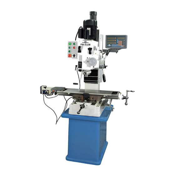
- Page 1 Model PM-932M Heavy duty milling machine 6-speed gear head Powered table (X axis) Powered headstock (Z axis) Quill DRO & depth stop Total weight 1000 lbs Cast iron stand Quality Machine Tools, LLC 701 Parkway View Drive Pittsburgh, PA 15205...
- Page 2 This manual contains essential safety advice on the proper setup, operation, maintenance, and service of the PM-932M milling machine. Failure to read, understand and follow the manual may result in property damage or serious personal injury.
-
Page 3: Section 1 Introduction
Section 1 INTRODUCTION MODEL 932M Milling Machine features and specifications General information The 932M is a robust "square column" mill designed for day-in, day-out use in the busy model shop. With an all- up weight of 1000 lbs it can handle far more than the typical small machine, including end mills up to 1-1/4" and face mills up to 3". - Page 4 Dimensions Weight, including cast iron stand 990 lb Size W 49-1/2" x D 34-1/2" x H 75-1/4" Stand footprint Approx. W 18-1/2" x D 27" Electrical 220V, 60Hz, 1φ, 15A breaker Power requirement Full load current 8.6A, spindle motor only Power cord 14 AWG x 6 ft Motors...
- Page 5 Everyday precautions This machine is designed for milling and drilling operations by experienced users familiar with metal-working hazards. Untrained or unsupervised operators risk serious injury. Wear ANSI-approved full-face or eye protection at all times when using the machine (everyday eyeglasses are not reliable protection against flying particles).
-
Page 6: Section 2 Using The Mill
Section 2 USING THE MILL FRONT PANEL CONTROLS Connect the mill to a 220Vac source. Press the green Power button to energize the main contactor in the control box. The power lamp, top left, should light, indicating that power is available to all motors. -
Page 7: Moving The Table
INSTALLING AND REMOVING TOOLING The spindle and drawbar are designed for R-8 taper collets, drill chucks and other arbors with the standard 7/16"-20 internal thread. The drawbar is threaded into the R-8 device by a few turns of the upper nut, which is solidly pinned to the bar. -
Page 8: X-Axis Power Feed
1. Install an edge-finder in collet or chuck (a tip diameter of 0.2" is assumed). 2. Lock the X-axis by tightening both leaf-screws, Figure 2-3 (1). 3. If the reference edge is to the back the spindle centerline, do nothing; if not, rotate the Y-axis handwheel clockwise to send the workpiece backwards (toward the column). - Page 9 disconnect power. Investigate and resolve power feed problems – such as X-axis locks not free, or gears too tightly engaged (see Section 6, Installation). Allow a cooling interval, press the reset button, then restore power. Limit switch Stop blocks on the front surface of the table can be independently set to limit travel to left and right, Figure 2-3 (3).
- Page 10 will jump up by 0.01" or more. To avoid this, make sure the fine control is firmly clockwise, lightly loading the quill rack, before releasing the locking lever. The DRO is in metric mode when switched on. Press the mm/in button to display inches. By pressing and holding the Up arrow (incrementing) or Down arrow (decrementing) the display can be set to a chosen value.
- Page 11 THREADING OPERATIONS When threading a drilled hole it is essential to align the threading tap properly in the bore. The mill is often used for this purpose, ideally with a dedicated (non-slip) tap holder or, for production work, an auto-reverse tapping attachment.
- Page 12 Set the headstock to the desired angle by reference to the tilt scale on the headstock base casting, then re-tighten the nuts. The tilt scale was carefully installed in manufacture, and is good to within ± 1/4 A more accurate means of angle measurement will be needed if the project calls for greater precision.
- Page 13 9. Reposition the 1-2-3 block to the opposite location on the table. 10. Swing the indicator holder to the new location, then lower the spindle – fine downfeed again – to give the same dial indicator reading as in step (7). If the headstock is perfectly trammed –...
- Page 14 behind the fixed jaw, Figure 2-15. There is no "right" deviation; what is acceptable depends on the project. Setting up the vise without keys If shimming is unacceptable, remove the keys and align the vise by eye. With one of the clamp nuts snug, but not tight, tighten the other one just short of fully-tight (but tight enough so the vise won't budge without a definite tap from a dead-blow mallet).
-
Page 15: Section 3 Maintenance
Section 3 MAINTENANCE Unplug the 220V power cord before any maintenance operation! Lubrication Oils are classified according to their viscosity. There are several viscosity indexes, the main ones being ISO (International Standards Organization) and SAE (Society of Automotive Engineers). SAE adds another complication with different indexes for engine and gear oils, further sub-divided into lists with and without the suffix W, meaning "multigrade". - Page 16 Figure 3-2 Gearbox fill plug and sight glass (inset) Figure 3-3 Quill rack The vent is open to the atmosphere to prevent the develop- ment of anaerobic organisms in the oil. The attached tube prevents spillage at high clockwise tilt angles. Quill rack and pinion Lower and lock the quill, Figure 3-3.
- Page 17 Leadscrew backlash correction When alternating between clockwise and counter clockwise rotation of the X or Y leadscrews, the handwheel moves freely but the table stays put. This is backlash, a feature of all leadscrews other than the precision variety found on CNC machines.
- Page 18 Power feed (X-axis) brush replacement There are two carbon brushes on the power feed motor. If removed for inspection, they should be replaced in the same orientation. Replace both when worn down to about 0.2". PM-932 Manual 2014 v9.docx...
-
Page 19: Section 4 Parts
Section 4 PARTS PLEASE NOTE 1. All dimensions are in mm 2. Item quantity 1 piece unless otherwise stated in brackets (…) 3. Standard hardware items are available from multiple sources, and are not given a manufacturer's part number. To order proprietary parts, please give the drawing reference number, together with the manufacturer's part number, and the revision number of this manual (see the v number in the page footer). - Page 20 PM-932 Manual 2014 v9.docx...
-
Page 21: Head Components
20010B Headstock Key: 6 x 6 x 14 Roll pin: 3 20011B Headstock top plate Key: 6 x 6 x 28 Screw: M8 1.25 x 30 Retaining ring: 62, int (2) Ball, 8 mm (2) 20024B Spacer Retaining ring: 35, int (2) Spring (2) 20133B Spindle end cap 20018B End cap... - Page 22 PM-932 Manual 2014 v9.docx...
- Page 23 Gear motor: 220V, 1φ 10013 Column Ball bearing: 604 (2) 10016 Headstock base casting Retaining ring: 42, int Screw: M8 1.25 x 25 (4) 10025 Z-axis gib 10015 Flange Screw: M8 1.25 x 20 (4) 10106 Screw: gib adjustment (2) 10116 Z-axis leadscrew Motor base (column cap)
- Page 24 Not shown: M12 1.75 x 190 base-to-stand attachment screws and washers (4) PM-932 Manual 2014 v9.docx...
- Page 25 10010 Base Oiler (3) Screw: M8 1.25 x 45, Cap Screw: M12 1.75 x 190 (4) Locking leafscrew (4) Screw: M8 1.25 x 12, Cap 10021 Y-axis leadscrew flange Pin: 8 x 30 (6) 10022 Table gib (X-axis) 10106 Screw: gib adjustment (4) 10011 Saddle Screw: M5 0.8 x 25, Cap (4)
-
Page 26: Control Box Components
CONTROL BOX COMPONENTS PM-932 Manual 2014 v9.docx... - Page 27 SPINDLE MOTOR CAPACITORS Z-AXIS MOTOR & LIMIT SWITCH WIRING (back of column) Electrical system (schematic on following page) All switch contacts are shown in their "normal" condition (= not actuated). The 220V ac supply to all devices except the transformer is switched by contactor KM1. ...
- Page 28 PM-932 Manual 2014 v9.docx...
-
Page 29: Section 5 Installation
Section 5 INSTALLATION THESE ARE THE MAIN POINTS TO WATCH OUT FOR! But read the following pages for more information Handling the mill is at least a two-man job. Hand-crank the headstock down until the spindle nose is just clear of the table. Remove the hand crank, and set it aside. - Page 30 Uncrating the mill The PM-932M is shipped in two packing cases strapped together, the lower case for the machine, the upper one for the stand. If available, use a forklift to remove the base. If not, an "engine hoist" such as that shown in Figure 5-1 may be used.
- Page 31 won't fit in the pockets). With the stand in its approximate working location, level it using the rim of the tray casting. Final leveling should be done when the machine is installed and bolted to the stand. Timesaving suggestion The tray casting slides freely on top of the stand. This makes it difficult to keep the holes aligned when the mill is lowered into place.
- Page 32 Installing the mill 1. Raise the mill to just clear the stand tray casting, then roll the mill into position. 2. Lower the mill onto the tray using taper drift(s) to align the mounting holes. 3. Remove the two temporary tray-locating screws/dowels, if fitted, then install the four mounting M12 x 190 bolts with washers.
- Page 33 Do not power the X-axis motor at this time! Crank the handwheel a few turns in both directions. If the motor is properly installed, there should be little resistance on the handwheel, and no noise other than what can be expected of straight-cut gears. If other noises are heard, it may be that the motor is slightly tilted down.
- Page 34 9. Crank handle removed? Headstock locking screws loosened? Press and hold the Up button to run the headstock up the column. Check that the motor stops as the upper limit switch is actuated, Figure 5-7. 10. Check for no obstructions, then press and hold the Down button to run the headstock down to the lower limit.
Need help?
Do you have a question about the PM-932M and is the answer not in the manual?
Questions and answers